

Page 1

ILE-61 SENSING HEAD
Instruction Manual PL-376
November 2001
Page 2

Safety Guidelines
Warning notices must be observed to ensure personal safety as well as that of others, and to
protect the product and the connected equipment. These warning notices are accompanied
by a clarification of the level of caution to be observed.
Qualified Personne l
This device/system may only be set up and operated in conjunction with this manual.
Qualified personnel are only authorized to install and operate this equipment in accordance
with established safety practices and standards.
Warning: This product can only function properly and safely if it is correctly transported,
stored, installed, set up, operated, and maintained.
Note: Always use product in accordance with specifications.
Copyright Siemens Milltronics Process
Disclaimer of Liability
Instruments Inc. 2001. All Rights Reserved
This document is available in bound version and in
electronic version. We encourage users to
purchase authorized bound manuals, or to view
electronic versions as designed and authored by
Siemens Milltronics Process Instruments Inc.
Siemens Milltronics Process Instruments Inc. will
not be responsible for the contents of partial or
whole reproductions of either bound or electronic
versions.
MILLTRONICS®is a registered trademark of Siemens Milltronics Process Instruments Inc.
Contact SMPI Tech nical Publicat io ns at the following address:
Technical Publications
Siemens Milltronics Process Instruments Inc.
1954 Technology Drive, P.O. Box 4225
Peterborough, Ontario, Canada, K9J 7B1
Email: techpubs@milltronics.com
While we have verified the contents of
this manual for agreement with the
instrumentation described, variations
remain possible. Thus we cannot
guarantee full agreement. The
contents of this manual are regularly
reviewed and corrections are included
in subsequent editions. We welcome
all suggestions for improvement.
Technical data subject to change.
For the library of SMPI instruction manuals, visit our Web site: www.milltronics.com
© Siemens Milltronics Process Instruments Inc. 2001
Page 3

Table of Contents
ILE-61 Sensing Head........................................................................................................... 2
Specifications...................................................................................................................... 3
Installation ........................................................................................................................... 6
Sensing Head ...........................................................................................................................................6
Sensing Plate ...........................................................................................................................................6
Viscous Damper .......................................................................................................................................7
Interconnection ........................................................................................................................................7
Non-Hazardous Unit without LVDT Conditioner Card ..........................................................7
Non-Hazardous Unit with Sensing Head Mounted LVDT Conditioner Card ..................8
Non-Hazardous Unit with Remote-Located LVDT Conditioner Card ...............................9
Calibration.......................................................................................................................... 10
General .....................................................................................................................................................10
LVDT Output ............................................................................................................................................10
Zero Adjustment ..........................................................................................................................10
Span Test .......................................................................................................................................11
Sensing Head Level Test ...........................................................................................................11
Integrator Calibration ...........................................................................................................................12
Maintenance and Spare Parts........................................................................................ 13
Maintenance ..........................................................................................................................................13
Spare Parts .............................................................................................................................................13
Inner Gasket Placement ......................................................................................................................13
Range Springs ................................................................................................................... 15
General .....................................................................................................................................................15
Range Spring Removal ........................................................................................................................15
Range Spring Replacement ................................................................................................................15
Flowmeter Recalibration .....................................................................................................................15
Troubleshooting................................................................................................................. 16
Linearity.............................................................................................................................. 17
ILE - 61 Sensing Head Outline and Mounting .............................................................18
ILE - 61 Part Identification Diagram .............................................................................19
ILE - 61 Part Identification Table ..................................................................................20
7ML19981CX01 ILE-61 Sensing Head – INSTRUCTION MANUAL Page 1
Page 4

ILE-61 Sensing Head: Introduction
The Milltronics ILE-61 Sensing Head is used for continuous in-line weighing of powdered
or granular dry bulk solid materials. The material is directed toward the sensing plate.
The horizontal impact force of the material, deflecting the sensing plate, displaces the
core of the sensing head LVDT (linear variable differential transformer). The LVDT output
signal is proportional to material flowrate.
LVDT
moving beam travel
impact force
sensing plate
The ILE-61 sensing head is used with Milltronics E-300 (general purpose), A-300 (aerated
gravity conveyor), and V-300 (vertical material drop) dry solids flowmeters.
.
E-300 A-300 V-300
Page 2 ILE-61 Sensing Head – INSTRUCTION MANUAL 7ML19981CX01
Page 5

Specifications
ILE-61 Sensing Head
Operating Range
• 0 to 20 TPH min, 0 to 300 TPH max
Product
• fine powder to 25 mm (1")
Product Temperature
• -40 to 232°C (-40 to 450°F)
Ambient Temperature
• -40 to 60°C (-40 to 140°F)
Accuracy
• 1% of full scale
Repeatability
•0.2%
Classification
• CSA certified, general purpose
Range Spring
• selected to suit application
Construction
• cast aluminum frame with fibreglass rear cover
Mounting
•base mount
7ML19981CX01 ILE-61 Sensing Head – INSTRUCTION MANUAL Page 3
Page 6

Sensor Type
• LVDT (linear variable differential transformer)
LVDT Excitation:
• 2.50 Vac @ 2.9 kHz (supplied by Flowmeter Integrator or LVDT Conditioner Card)
LVDT Output:
• 0 - 0.75 Vac @ 2.9 kHz
Damping Fluid:
• 10 - 100 cm2/s (1000 - 10 000 cs) silicone, (Dow Corning 200)
Options:
• Epoxy, Teflon1,® or Tufram2® frame coating
• Epoxy painted mild steel or stainless steel rear cover
• CSA Class I - groups C & D, Class 2 - groups E, F, & G
Approvals
•CE
SENSING PLATE
Construction:
• 304 stainless steel
Options:
• 316 stainless steel 6
• UHMW polyurethane or Ceramic Tile lining
• Teflon®or plasma coating
LVDT Conditioner Card
Power
• ± 5 Vdc (typically from an Accumass integrator)
1.
Tufram®is a registered trademark of General Magnaplate.
2.
Teflon®is a registered trademark of DuPont.
Page 4 ILE-61 Sensing Head – INSTRUCTION MANUAL 7ML19981CX01
Page 7

Ambient Temperature
• -20 to 50°C (-2 to 122°F)
Input
• 0 to 1.0 V from LVDT
Output
• 0 to 50 mV to Accumass SF500 (maximum 300 m (1000 ft) separation between
Conditioner Card and integrator)
Approvals
•CE
Enclosure
• NEMA 4 (remote mounted unit)
Cable
For connection between LVDT Conditioner Card and Integrator
• Belden 8404, 4 conductor, shielded 20 AWG or equivalent, 150 m (500 ft) maximum
• Belden 9260, 6 conductor, shielded 20 AWG or equivalent, 300 m (1000 ft) maximum
For connection between LVDT and remote LVDT Conditioner Card,
or directly between LVDT and Integrator
• Belden 8404, 4 conductor, shielded 20 AWG or equivalent, 300 m (1000 ft) maximum
7ML19981CX01 ILE-61 Sensing Head – INSTRUCTION MANUAL Page 5
Page 8
Installation
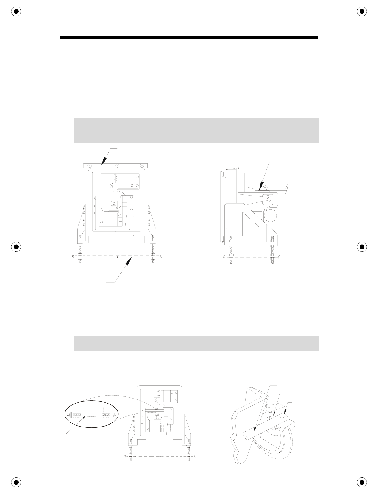
Sensing Head
1. With the flowmeter housing installed, mount the ILE-61 to a rigid support structure.
2. Remove the ILE-61 fibreglass cover. With the outer gasket in place, bolt the ILE-61 to
the housing.
3. Adjust the sensing head leveling hardware (provided) to establish level in both
horizontal planes.
Note: Ensure the sensing head mounting structure is capable of supporting the
dynamic material impact forces as well as the weight of the sensing head.
spirit level
moving beam
(machined
surface)
rigid support
Sensing Plate
1. Open the flowmeter housing access door.
2. With the sensing head cover removed, remove the taper pin.
3. Insert the sensing plate shaft fully into the sensing head socket.
Note: Ensure the sensing plate shaft is installed with the flat side up.
4. Insert the taper pin (flat side down), from the left side.
5. Tighten the right taper pin nut to lock the sensing plate shaft in place.
6. Tighten the left taper pin nut.
taper pin
(flat side down)
shaft
socket
flat side up
Page 6 ILE-61 Sensing Head – INSTRUCTION MANUAL 7ML19981CX01
Page 9
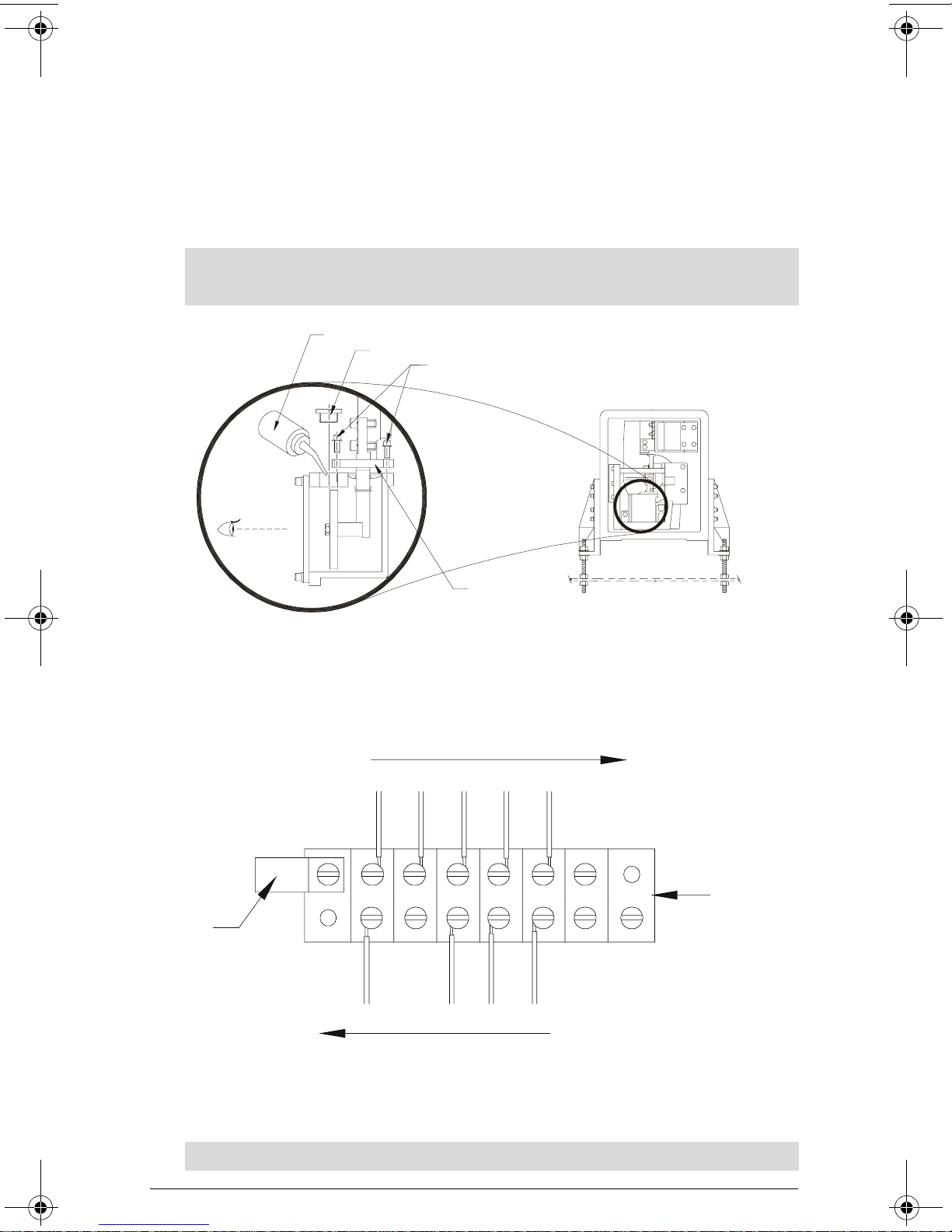
Viscous Damper
fill
1. Remove the 2 damper cover shipping screws. The damper cover will be held up by a
spring.
2. If necessary, top up the damper (to near overflowing) with the damping fluid
supplied.
3. Store the damper cover shipping screws, remaining damper fluid, and filler bottle for
future use.
Note: The damper must be full and free of air bubbles with the damper cover in the UP
position during flowmeter operation.
er bottle
filler plug
shipping screws
damper cover
Interconnection
Non-Hazardous Unit without LVDT Conditioner Card
* See note below for Encapsulated (Hazardous-rated) LVDT color codes.
to LVDT
R
B
Y
L
E
U
L
C
O
M
YEL = WHITE
BLU = ORANGE
GRN = YELLOW
E
D
E
E
X
X
C
C
+
–
cable
clamp
to integrator
(LVDT connection)
B
G
L
R
K
N
S
I
G
–
*For Encapsulated LVDT (hazardous)
flowmeter
terminal
block
Note: Ground shield at Integrator only.
7ML19981CX01 ILE-61 Sensing Head – INSTRUCTION MANUAL Page 7
Page 10

Non-Hazardous Unit with Sensing Head Mounted LVDT
/
Conditioner Card
• Not applicable to Hazardous-rated units
• LVDT to LVDT Conditioner Card connections are made by Milltronics
LVDT
Milltronics LVDT Conditioner Card
LVD T IN TE GR ATO R
S
I
C.T.S
E
E
C
X
X
O
C
C
M
+
-
S
I
H
G
L
-
D
G
E
X
C
O
C
+
M
S
S
E
H
I
X
L
G
C
D
+
-
RED
BLUE
YELLOW
BLACK
GREEN
11 14 12
SF500
Integrator
LCA+
LCA-
LCB+
LCB-
SHLD
LCC+ SIG
LCC- COM
LCD+ CNST
-LOAD CELL INPUTS-
LCD-
SHLD
10
4
5
6
7
8
9
-LOAD CELL-
V+
S+
EXCITATION
SHLD
111
122
133
14
15
16
17
18
*
S-
V-
*Where separation between the integrator and LVDT conditioner exceeds 150 m (500 ft):
• Remove the jumpers SF500 terminal 11/12 and 13/14
• Run additional conductors:
- from SF500 terminal 12 to conditioner terminal block marked “Integrator +EXC”
- from SF500 terminal 13 to conditioner terminal block marked “Integrator –EXC”
For further connection information on specific LVDTs, consult Milltronics.
♦
Note:
1. Shields are common, but not grounded to chassis. Run cable shields through
SHLD terminals and ground at Integrator only.
2. Ensure that connection between TB 2 and TB 17 is made.
Page 8 ILE-61 Sensing Head – INSTRUCTION MANUAL 7ML19981CX01
Page 11

Non-Hazardous and Hazardous Units with Remote-
/
Located LVDT Conditioner Card
*LVDT
Milltronics LVDT Conditioner Card
(in non-hazardous location)
LVD T IN TE GR ATO R
S
I
E
X
C
+
11 14 12
G
E
X
C
O
C
-
M
SF500
Integrator
E
X
C
+
**
RED
BLUE
YELLOW
GREEN
LCA+
LCA-
LCB+
LCB-
SHLD
LCC+ SIG
LCC- COM
LCD+ CNST
-LOAD CELL INPUTS-
LCD-
SHLD
10
4
5
6
7
8
9
-LOAD CELL-
**For Encapsulated LVDT (hazardous)
**Junction box included with hazardous-rated unit.
C.T.S
E
C
O
M
V+
S+
I
G
-
S-
V-
X
C
-
EXCITATION
SHLD
YEL = WHITE
BLU = ORANGE
GRN = YELLOW
111
122
133
14
15
16
17
18
S
H
L
D
*
S
S
H
I
L
G
D
+
*Where separation between the Integrator and LVDT conditioner exceeds 150 m (500 ft):
• Remove the jumpers SF500 terminal 11/12 and 13/14
• Run additional conductors:
- from SF500 terminal 12 to conditioner terminal block marked “Integrator +EXC”
- from SF500 terminal 13 to conditioner terminal block marked “Integrator –EXC”
For further connection information on specific LVDTs, consult Milltronics.
♦
Note:
1. Shields are common, but not grounded to chassis. Run cable shields through
SHLD terminals and ground at Integrator only.
2. Ensure that connection between TB 2 and TB 17 is made.
7ML19981CX01 ILE-61 Sensing Head – INSTRUCTION MANUAL Page 9
Page 12

Calibration
LVDT
LVDT
General
A Test Weight is a calibration reference used to simulate a material impact force (Test
Rate) on the flowmeter sensing plate during the integrator Span calibration. The test
weight is also used to perform a test to verify that the flowmeter sensing head is level.
The Test Rate should be 60 to 80% of the system Design Rate.
To determine the Test Rate produced by a specific Test Weight...
Test Rate (TPH) = Test Weight (grams)
45* grams/ TPH
Alternatively, to determine the Test Weight required for a specific Test Rate:
Test Weight (grams) = 45* grams x Test Rate (in TPH)
1 TPH
*Use 60 grams for A-300 flowmeters.
e.g. If the Test Weight used with an E-300 flowmeter is 7000 grams...
Test Rate = 7000 grams
45 grams/TPH
= 155 TPH
Note: Use metric tons per hour (t/h) or short tons per hour (STPH) as applicable for TPH.
LVDT Output
Zero Adjustment
1. Connect a voltmeter across the LVDT green and yellow (or yellow and white) wires.
2. With no load applied to the sensing plate, observe 0.10 Vac on the voltmeter.
Note: If the LVDT output is 0.10 to 0.05 Vac, skip to Span Test, otherwise, proceed as
follows:
a.Loosen the locknut on the LVDT threaded core.
b.Turn the core in/out of the LVDT until 0.10 to 0.05 Vac is obtained.
c.Tighten the locknut, ensuring the measured value is maintained.
core
moving beam
locknut
increase decrease
to integrator
LVDT EXC. or
LVD T con dit ion er
card
± 0.05 Vac
>± 0.05 Vac
Page 10 ILE-61 Sensing Head – INSTRUCTION MANUAL 7ML19981CX01
Page 13

Span Test
1. Gently push the sensing head moving beam to the right. The LVDT output should
increase steadily until a level of 0.75 to 1.0 Vac is achieved.
2. Gently push the sensing head moving beam to the left. The LVDT output should
decrease steadily until zero is reached and then increase to 0.25 to 0.50 Vac.
3. Ensure the LVDT output always returns to 0.10 to 0.05 Vac, (on the right hand side of
zero), when pressure on the moving beam is released.
Note: The LVDT core must not contact the inside of the LVDT over the range of core
travel. The actual LVDT core travel during this procedure is less than 3 mm (1/8").
0 . 7 5 0
to
1 . 0 0 0
0 . 0 5 0
to
0 . 1 5 0
Sensing Head Level Test
1. With the voltmeter still connected to the LVDT output, hang the test weight directly
off the sensing plate.
2. Observe the display value does not change by more than 0.01 Vac.
0 . 0 1 5
to
0 . 5 0 0
Note: If the change is greater than 0.01 Vac, adjust the sensing head level until the
change with and without the test weight on the sensing plate is less than 0.01 Vac.
Remove the test weight and readjust the LVDT Output Zero, if necessary. If this
procedure is performed after the integrator is calibrated, a new integrator Zero and
Span calibration, Span Adjust, and Factoring (if required) should be performed.
sensing plate
7ML19981CX01 ILE-61 Sensing Head – INSTRUCTION MANUAL Page 11
changes < 0.01 Vac
test weight
Page 14

Integrator Calibration
Refer to the flowmeter integrator instruction manual for integrator calibration
instructions.
To apply the Test Weight for the Span calibration:
1. Mount the calibration bracket (stored on the left side of the cast frame).
2. Attach one end of a string (monofilament fishing line or fine flexible cable) to the
Tes t Wei ght .
3. Route the other end of string over the calibration pulley.
4. Attach the free end of the string to the string fixing bolt. Ensure the string rests in the
bolt groove.
Note: Ensure the Test Weight is suspended free from obstruction.
5. When the calibration is complete, return the calibration bracket to the storage
position.
string fixing bolt
calibration arm
test weight
Note: Accurate calibration is not assured until material tests and a Span Adjust are
performed.
Page 12 ILE-61 Sensing Head – INSTRUCTION MANUAL 7ML19981CX01
Page 15

Maintenance and Spare Parts
Maintenance
A program of routine maintenance should be established to ensure the highest
achievable level of performance is maintained. Good housekeeping practices in the area
of the flowmeter are recommended.
Maintenance Description Frequency
Regular Monthly Semi-Annual Annual
Clean area around flowmeter
Check sensing place surface*
Check damping fluid
Check sensing head inner gasket
Check sensing plate wear
Check test weight Rate display
Test flowmeter linearity
* Material buildup (if any) in the impact area of the sensing plate should be removed.
!
!!!
!! ! !
!!!
!!!
!!!
!!
Spare Parts
Milltronics recommends a spare inner and outer gasket, sensing plate, and spare
damping fluid be kept on hand.
Contact Milltronics or your distributor for spare parts ordering information.
!
Inner Gasket Placement
Should it ever be necessary to replace the sensing head inner gasket, refer to the
Installation and Figures sections of this instruction manual prior to performing the
following procedure.
1. Remove the ILE-61 fibreglass cover, (10 bolts).
2. Bolt down the viscous damper cover to the shipping position, (2 bolts).
3. Remove the sensing plate from the sensing head.
4. Remove the inner retaining ring, (6 bolts).
5. Remove the upper and lower hinge block bolts, (4 per block).
6. a. Hazardous versions, remove the LVDT core and LVDT, (3 bolts), or
b. Non Hazardous, remove the LVDT cable TY WRAPs (2) and disconnect LVDT
connections.
7. While supporting the main assembly, remove the secondary static beam bolts (3 per
side).
7ML19981CX01 ILE-61 Sensing Head – INSTRUCTION MANUAL Page 13
Page 16

8. Draw the main assembly away from the main frame.
Note: The main assembly is heavy and awkward to handle; ensure it is
supported well.
9. Remove the outer retaining ring and inner gasket, (8 bolts).
10. Install the new inner gasket and reverse the procedure (steps 1 through 9).
11. Perform the LVDT output zero procedure.
12. Referring to the integrator instruction manual, perform an integrator Zero and Span
calibration. Perform a Span Adjust if calibration accuracy appears affected.
Page 14 ILE-61 Sensing Head – INSTRUCTION MANUAL 7ML19981CX01
Page 17

Range Springs
General
The Range Spring establishes the range of sensing head moving beam travel for a given
range of material flow. This spring installed, is selected and positioned according to the
specified Design Rate of the application.
For best operation the range spring should provide 0.75 to 2.4 mm (0.030 to 0.094") of
moving beam travel from the static zero to the Design rate operation position. The moving
beam travel may be inferred by the value of the LVDT green and yellow (or yellow and
white) wires.
With the 2.5 Vac, 2.9 kHz LVDT excitation supplied:
• 0.75 mm of moving beam movement = 0.188 Vac
• 2.40 mm of moving beam movement = 0.600 Vac
Should the Design Rate of the flowmeter application change, it may be necessary to
reposition the original range spring, or select and install another range spring, to obtain
the optimum moving beam travel (LVDT output) range. Moving the range spring to a
location further away from the pivot point leaf spring, increases the maximum flowrate
capacity.
Range Spring Remov al
1. Observe the range spring mounting position. (3 positions are available)
2. Loosen the range spring locknut.
3. Remove the range spring center bolt and 4 flange mounting bolts.
4. Remove the range spring from the range spring assembly.
Range Spring Replacement
1. Install the new range spring in the range spring assembly.
2. Mount the range spring assembly by the 4 flange mounting bolts.
3. With the moving beam in the static zero position, turn the range spring until the base
just touches the beam, and then turn 1 complete revolution more.
4. Install the range spring center bolt and tighten the range spring locknut.
Flowmeter Recalibration
After removing and replacing the range spring, the flowmeter and integrator should be
recalibrated.
1. Perform the LVDT output Zero procedure. Refer to Calibration.
2. Perform an integrator Zero and Span calibration. Refer to the integrator manual,
Calibration.
3. Perform a Span Adjust and Factoring as required. Refer to the integrator manual,
Calibration.
7ML19981CX01 ILE-61 Sensing Head – INSTRUCTION MANUAL Page 15
Page 18

Troubleshooting
Every Millltronics ILE-61 Sensing Head is subjected to extensive quality assurance
procedures to ensure the highest degree of quality, reliability, and performance is
achieved.
The following listing indicates the probable cause, and proper course of action to be
taken should the specified fault symptom occur.
Symptom Cause Action
Integrator Rate display doesn’t
change when sensing plate is
moved
Span adjustment does not
have enough range
Measurement results are not
repeatable
Accuracy varies with material
flowrate
Wrong or bad integrator
connection
Viscous damper lid in shipping position
Integrator not prepared for
operation
Range spring not suited to
application
Sensing head not level
Moving beam is mechanically
limited
Leaf springs are damaged
Material flow patterns vary
Non-linear operation Refer to Linearity
Refer to Fig. 4 - Integrator
LVDT Interconnection
Refer to Installation/ Viscous
Damper
Program and Calibrate the
integrator
Refer to Range Springs
Refer to Installation and
Calibration/Sensing Head
Level Test
Ensure moving beam does not
hit travel stops between -20%
and 150% flowrates
Replace leaf springs,
recalibrate flowmeter, and
integrator
Consult Siemens Milltronics or
your distributor
Page 16 ILE-61 Sensing Head – INSTRUCTION MANUAL 7ML19981CX01
Page 19

Linearity
To test linearity, at least 3 test weights are used. Each weight represents a different Test
Rate. Record the integrator Rate display value associated with each test weight applied
to the flowmeter.
If all the recorded display values are accurate, the flowmeter measurement is linear.
e.g. For an E-300 flowmeter Design Rate of 200 TPH, the following three test weights
could be used:
• 9000 g (19.82 lb.) = 100% Design Rate = 200 TPH
• 6750 g (14.87 lb.) = 75% Design Rate = 150 TPH
• 4500 g (9.91 lb.) = 50% Design Rate = 100 TPH
If non-linear results are obtained, ensure:
• at no flow, the moving beam does not rest on the zero stop bolt.
• at 150% Design Rate, the moving beam does not reach the full flow stop bolt.
• at 150% Design Rate, the LVDT output does not exceed 1.0 Vac.
• the damper piston does not touch the damper cylinder wall at any flow rate.
• the LVDT core does not touch the inside of the LVDT at any flow rate.
• the viscous damper fluid is free of large air bubbles and the fluid level is correct.
• the range spring operates in compression from 0 - 150% flow rate.
• the sensing head leaf springs are in good condition.
If the test weight linearity test is successful, yet actual material test results are nonlinear, ensure there is no air circulation in the housing sensing plate area. If there is no
significant air circulation in the flowmeter housing while running material, the material
flow pattern is probably non-linear.
Non-linear material flow patterns can often be corrected by minor modifications to the
material infeed, or upstream piping. Some integrators are equipped with a linearization
function to compensate for non-linear material flow patterns. Stand alone linearizing
devices are also available for this purpose.
Note: Electronic linearization should not be used to correct non-linear test weight
results.
7ML19981CX01 ILE-61 Sensing Head – INSTRUCTION MANUAL Page 17
Page 20

ILE - 61 Sensing Head Outline and Mounting
Notes:
1. Refer to Flowmeter drawing for sensing head mounting hole to flowguide centre line dimension.
2. Sensing head support plate should be rigid and independent of flowmeter housing.
3. All dimensions in millimeters: ( ) denotes inches.
4. Ensure that the outer gasket seal to the Flowmeter housing wall is dust tight.
outer gasket
conduit entry
½” NPT internal
fibreglass cover
560
(22.05)
318
(12.52)
60
(2.36)
300
(11.81)
420
(16.54)
sensing
plate
see note 1
support plate
(by customer)
16 (0.63) dia.
(4 levelling rods)
560
(22.05)
500
(19.64)
490
(19.29)
340
(13.34)
380
(14.96)
as req’d
8 (0.31 dia. 18 bolts
on 460 (18.11) BCD.
(22.44)
outer
gasket
sensing head
376draft1.fm Page 18 Wednesday, November 21, 2001 1:54 PM
Page 21

ILE - 61 Part Identification Diagram
53 64
71
23
7429
49 66
25
68
24
51 61
73
75
26272873
56 65
8
31
32
6556
33
68 64
10 9
53 64 30 39 22 3437356636
49
38 47
19 56 65
41
53 64
40
56 54
4
78 49 63
5
20 21 76
13
15
16
6458
60 68
14
60
52
50
17
18
54
42 43 48
62 67
56 65
6
11
12
3
56 65
1
77
57 65
2
7
44 45 46
49 53
65
55
FIG. 3A
arm in operating
position
Detail "A"
arm in calibration position
See Detail "A"
376draft1.fm Page 19 Wednesday, November 21, 2001 1:54 PM
Page 22

ILE - 61 Part Identification Table
Identification # Description
1 ILE-61 body (cast frame)
2 Mounting Bracket (RH.)
3 Mounting Bracket (LH.)
4 Dynamic Beam (moving)
5 Static Beam (RH.)
6 Static Beam (LH.)
7 Damper Cylinder
8 Top Inner Leaf Spring Bracket
9 Top Outer Leaf Spring Bracket
10 Leaf Spring, qty 4
11 Bottom Inner Leaf Spring Bracket
12 Bottom Outer Leaf Spring Bracket
13 Outer Gasket Outer Ring
14 Outer Gasket Inner Ring
15 Outer Gasket (silicon or neoprene)
16 Inner Gasket Outer Retainer
17 Inner Gasket Inner Retainer
18 Inner Gasket
19 Calibration Arm
20 Calibration Pulley
21 Calibration Pulley Shaft
22 String Fixing Bolt
23 Damper Cover
24 Damper Cover Spring
25 Damper Window
26 Damper Shaft
27 Damper Piston
28 Damper Piston Shaft
29 Damper Fill Cap
30 Static Beam Stiffening Rod
31 Outer Leaf Spacer (qty 16)
32 Inner Leaf Spacer (qty 8)
33 Taper Pin
34 LVDT
35 LVDT Spring
36 LVDT Retainer
37 LVDT Transformer
38 Terminal Block (or 38A)
38A LVDT Conditioner Card
39 Nameplate
40 Fibreglass Cover
41 Cover Gasket
42 LVDT Core
43 LVDT Calibrating Flange
44 Range Spring
45 Range Spring Retainer (RH.)
46 Range Spring Retainer (LH.)
47 Cap Screw M3x20, SS, (qty 2)
Identification # Description
376draft1.fm Page 20 Wednesday, November 21, 2001 1:54 PM
Page 23

48 Cap Screw, M4x10, SS, (qty 3)
49 Cap Screw, M5x16, SS304, (qty 11)
50 Cap Screw, M6x12, SS, (qty 6)
51 Cap Screw, M6x20, SS304, (qty 2)
52 Cap Screw, M8x16, SS, (qty 8)
53 Cap Screw, M8x25, SS, (qty 15)
54 Cap Screw, M8x30, SS, (qty 14)
55 Cap Screw, M10x25, SS, (qty 4)
56 Cap Screw, M10x30, SS, (qty 38)
57 Cap Screw, M10x40, SS, (qty 10)
58 Bolt, Hex, M8x45, SS, (qty 18)
59 Washer, Elongated, SS, (qty 10)
60 Washer, Flat, M8, SS, (qty 30)
61 Washer, Lock, 6.1mm I.D., SS, (qty 2)
62 Washer, Lock, M4, SS, (qty 3)
63 Washer, Lock, M5, SS, (qty 8)
64 Washer, Lock, M8, SS, (qty 32)
65 Washer, Lock, M10, SS, (qty 52)
66 Washer, Plate, M5, SS, (qty 10)
67 Nut, Hex, M6, SS, (qty 1)
68 Nut, Hex, M8x1.25P, SS, (qty 23)
69 Nut, Lock, RS A, (qty 1)
70 Nut, Lock, RS B, (qty 1)
71 O-Ring, Damper Shaft (qty 1)
72 O-Ring, Damper Window (qty 1)
73 O-Ring, Damper Cover (qty 1)
Identification # Description
74 O-Ring, Damper Fill Cap (qty 1)
75 Retaining Ring, Damper Spring (qty 1)
Identification # Description
376draft1.fm Page 21 Wednesday, November 21, 2001 1:54 PM
Page 24

Page 25

Notes
Page 26

Notes
Page 27

Page 28

*7ML19981CX01*
 Loading...