

Page 1
HydroRangerPlus
33455070
Rev 2.1
Instruction Manual
PL-507
October 1997
T echnology based. Customer driven.
Page 2

hank you for purchasing Milltronics products. We endeavour to design
T
equipment that is simple to use and reliable in its operation, with the aim
of satisfying our customers' needs.
Milltronics has been designing and manufacturing process equipment since
1954. Our fields of expertise include ultrasonic and capacitance level
measurement, in-line weighing of dry bulk solids and motion sensing.
Milltronics is established world wide through associate offices and
representatives. Our network is continually being refined to provide our
customers with first rate sales information, engineering assistance and after
sales support.
For more details on our products and service, please contact us and we will
provide you with a listing of the offices or representatives nearest you.
Page 3

TABLE OF CONTENTS
TITLE PAGE #
INTRODUCTION
About this Manual 5
About the HydroRanger Plus 6
Important HydroRanger Plus Features 8
INSTALLATION
Environmental 9
Outline 9
Mounting 11
Programmer 17
ComVerter 17
Interconnection 18
PROGRAMMING
Program Mode Entry 27
Display 28
Keypad 29
Parameter Value Alteration 31
Special Parameters 31
Parameter Reset Features 31
Programming Security 32
OPERATION
Run Mode Entry 33
Display 34
Keypad 35
System Performance Evaluation 36
Performance Test Results 37
Maintaining Operation 38
APPLICATIONS
General Application 39
Wet Well Control (Pump Down) 42
Reservoir Control (Pump Up) 44
Rake Control (Differential Level) 46
Penstock Control 48
General Alarms 50
OCM (Open Channel Monitor) 52
Volume Calculation 54
Pumped Volume Total 56
Failsafe Operation 58
Application Assistance 60
3
Page 4

TITLE PAGE #
PARAMETERS
Security 61
Quick Start 62
Volume 65
Reading 67
Failsafe 69
Relays 71
mA Output 89
mA Input 94
Data Logging 95
OCM 105
Totalizer 119
Range Calibration 122
Temperature Compensation 124
Rate 126
Measurement Verification 128
Scanning 130
Display 131
Echo Processing 133
Advanced Echo Processing 136
Test 144
Measurement 146
Master Reset 148
TECHNICAL REFERENCE
Transmit Pulse 149
Echo Processing 149
Scope Displays 149
Distance Calculation 150
Sound Velocity 150
Scanning 151
Volume Calculation 152
Flow Calculation 153
Measurement Response 154
Relay Set Up 155
Maintenance 156
TROUBLESHOOTING
Troubleshooting Chart 157
Measurement Difficulties 158
SPECIFICATIONS
HydroRanger Plus 161
Programmer 163
Options 163
PROGRAMMING CHART 165
4
Page 5

INTRODUCTION
ABOUT THIS MANUAL
INTRODUCTION
This instruction manual provides information specific to the Milltronics
(HYDRO+) level monitor*. Other products (including transducers) associated with
Plus
a HYDRO+ based level monitoring system, are supplied with individual instructions.
All general start up information is included in the white pages. Refer to the grey pages
for additional information or technical assistance, if required.
After reading this INTRODUCTION and completing the physical INSTALLATION, first
time system installers may wish to use the
Guide, PL-439
INTRODUCTION
INSTALLATION
PROGRAMMING
OPERATION
APPLICATIONS
PARAMETERS
TECHNICAL REFERENCE
TROUBLESHOOTING GUIDE
SPECIFICATIONS
PROGRAMMING CHART
INTRODUCTION
HYDRORANGER PLUS Quick Start
for step by step start up instructions.
briefly describes key features.
step by step mounting and wiring procedure.
program mode LCD and keypad functions.
run mode LCD and keypad functions.
10 brief examples of common HYDRO+ uses.
specific programmable feature definitions.
detailed information for complex features.
quick problem solving techniques.
lists physical and operational characteristics.
space to record all programming for future
reference. (Also used as a Parameter index).
HydroRanger
INSTALLATION
"Programming is not complete until the Programming Charts are completed".
*
This manual applies to the wall, rack, and panel mount HYDRO+ versions.
For simplicity, the rack mount version is illustrated only
where necessary to identify version differences.
Throughout this manual (unless stated otherwise) "level" refers to the
PL-507 5
relative position of a monitored liquid surface.
REMEMBER!
Page 6
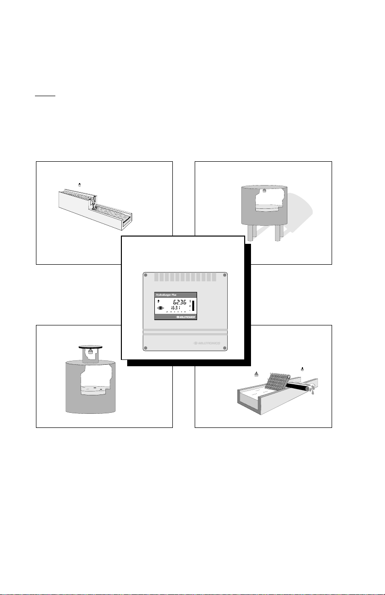
ABOUT THE HYDRORANGER PLUS
Reservoir
Screen Rake
The HydroRanger Plus is to be used only in the
manner outlined in the instruction manual.
The HYDRO+ includes the features of the successful Milltronics "HydroRanger 1"
PLUS a variety of new features, incorporating advances in electronic component,
manufacturing, and software technology.
This multi-purpose microprocessor based level monitor contains numerous features
ideally suited for liquid monitoring and pump control applications.
Open Channel
HYDRO +
%
3
5
214
Wet Well
A HYDRO+ level monitor, utilizing a single ultrasonic transducer (ordered separately),
accurately monitors level without contacting the surface monitored.
The HYDRO+ provides the transmit pulse to the transducer. The transducer emits
ultrasonic pulses in a narrow beam, perpendicular from the transducer face. The
HYDRO+ measures the time between pulse emission and reflection (echo) reception,
to calculate the transducer face to monitored surface distance.
The transducer internal temperature sensor is used to automatically compensate
for sound velocity variations due to air temperature changes within the
measurement range.
PL-507 6
Page 7
The HYDRO+ monitors levels 0.3 to 15 m (1 to 50 ft) from the transducer face, with
Alarm
outstanding accuracy, usually within 0.25% of range. (Ensure the transducer selected
suits the material and measurement range monitored).
TM
This versatility is accomplished by Milltronics patented Sonic Intelligence
, providing
high measurement reliability, regardless of operating conditions.
LCD
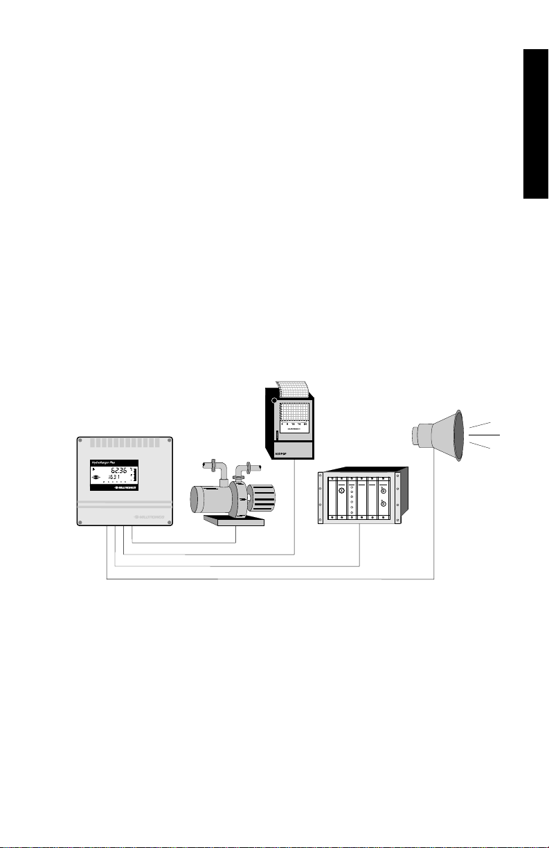
The HYDRO+ provides the following
(Liquid Crystal Display) Readings:
» Level, space, distance, volume, or remaining capacity in open or closed vessels.
» Differential level across a channel filter or screen (2 transducers required).
» Average level in a large vessel with an uneven material surface (2 transducers).
» Head, flow, or totalized flow in free flowing open channels.
» Pumped volume from wet wells or into reservoirs.
The HYDRO+ relays and/or mA output may be used as preset (or programmed as
desired) to activate alarms, pump controls, chart recorders, or virtually any process
control equipment.
Chart
Recorder
HYDRO +
INTRODUCTION
Pump
%
3
5
214
PLC
The HYDRO+ infrared interface permits one programmer to be used for any number
of HYDRO+ level monitors. Upon programming completion, the programmer may be
locked away for programming security. All Operator programming is stored in
non-volatile memory, unaffected by power interruption.
While the HYDRO+ is typically used to monitor liquid level, any process which
requires a distance measurement or object presence/lack of presence (within the
system maximum measurement range) is a candidate for HYDRO+ application.
Refer to APPLICATIONS for detailed descriptions of a small sample of process
measurement requirements to which the HYDRO+ may be applied.
PL-507 7
Page 8

IMPORTANT HYDRORANGER PLUS FEATURES
FIXED FEATURES
ENCLOSURE: Chemical resistant, light weight, dust/liquid tight.
LCD: Large digits and symbols for Readings and continuous
HAND PROGRAMMER: 20 tactile feedback keys, (ordered separately).
DOLPHIN COMPATIBLE: HYDRO+ / RS 232C interface, (ordered separately).
COMMUNICATIONS: Non-invasive infra-red digital data transfer.
SPEED: 16/32 bit microprocessor at 16.7 MHz clock speed.
RELIABILITY: Sonic Intelligence
PROGRAMMABLE FEATURES
Typically, a very small percentage of the HYDRO+ operator programmable features
require alteration from default settings. However, for demanding measurement
requirements any number of features may be adjusted as required.
Following is a list of the features that make the HYDRO+ easy to program, yet
versatile enough to handle complex level measurement requirements.
GENERAL FEATURES
DIRECT ACCESS: Any operator programmable feature may be accessed directly.
SCROLL ACCESS: Scroll forward or backward to key programmable features.
OPERATION: 7 modes of operation to suit specific requirements.
MATERIAL: Preset for optimum performance on all liquid surfaces.
RESPONSE: Slow, medium, or fast response to level changes.
UNITS: Readings in m, cm, mm, ft, in, %, (or any other units desired).
operating condition indication.
TM
Surface Mount Technology (SMT)
Immune to power interruptions. All programming is retained
indefinitely. Operating data is retained for 30 seconds min;
updated promptly upon resumption.
ADDITIONAL FEATURES (use as desired)
VOLUME: 8 pre-programmed tank shape options
2 universal tank shape programming methods
FLOW: Open channel flowrate and total, 5 pre-programmed flumes.
PUMPED TOTAL: Total volume pumped including/excluding inflow/discharge.
DATA LOGS: Time and Date of important operational events.
FAIL-SAFE: Automatic process control equipment activation.
RELAYS: 6 alarm functions, 7 pump functions, 5 control functions,
storm condition and energy saving pump function modifiers.
mA OUTPUT: 7 functions, range selectable and scalable, overrange limits.
mA INPUT: HYDRO+ features based on any level monitor mA output.
PL-507 8
Page 9
INSTALLATION
Installation shall only be performed by qualified personnel,
and in accordance with local governing regulations.
ENVIRONMENTAL
Choose a mounting location suited to the HYDRO+ enclosure.
The ideal HYDRO+ mounting location is where the:
1. Ambient temperature is always within -20 to 50°C (-5 to 122°F).
2. HYDRO+ display window is at eye level.
3. Cable length requirements are minimal.
4. Mounting surface is free from vibration.
Avoid mounting locations where the HYDRO+ is:
» exposed to direct sunlight, (otherwise, provide a sun shield).
» close to high voltage/current runs, contactors, SCR control drives, or
frequency inverters.
This product is susceptible to electrostatic shock.
Follow proper grounding procedures.
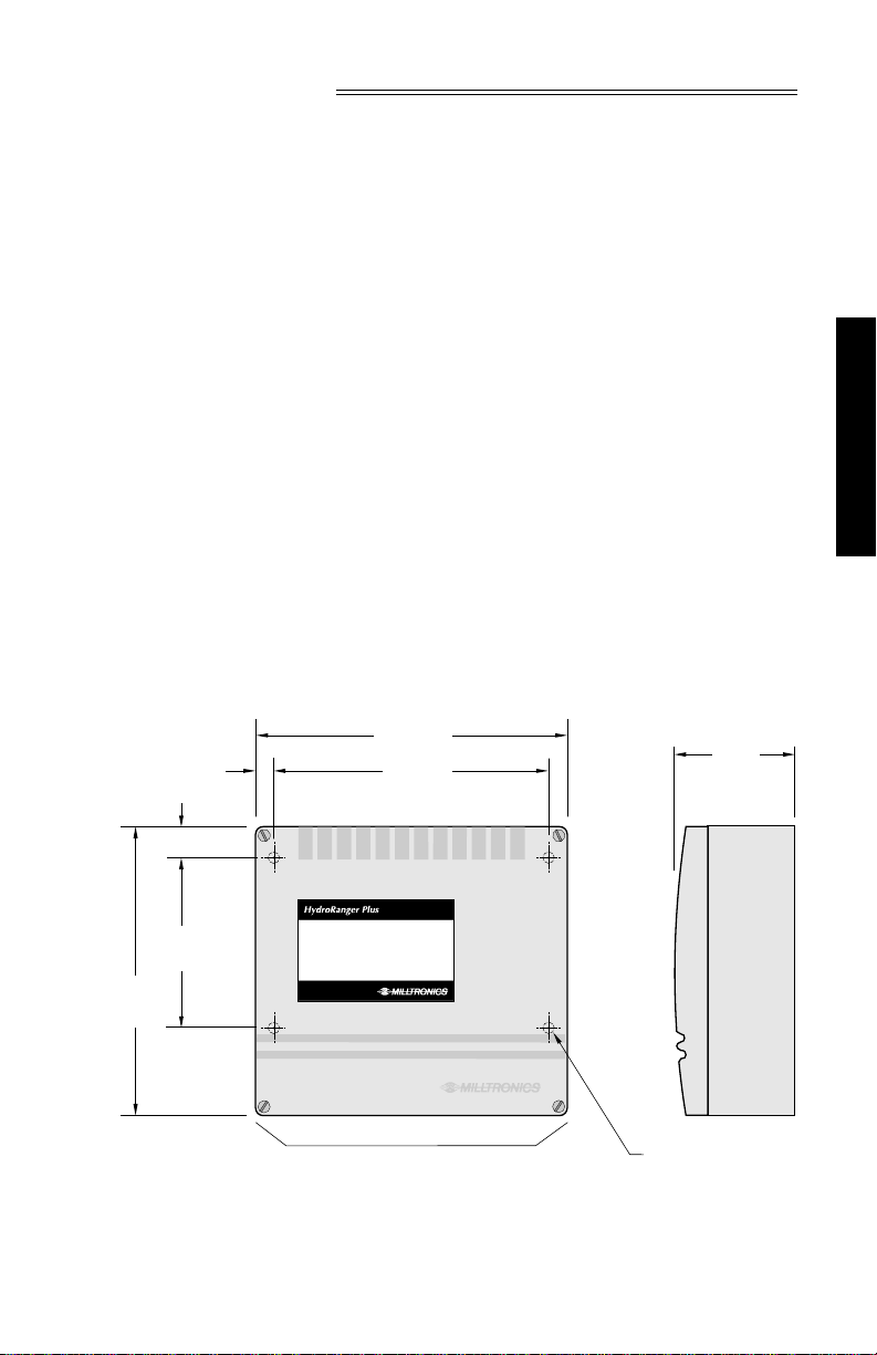
OUTLINE
WALL MOUNT
195 mm
(7.7")
13 mm (0.5")
20 mm (0.8")
168 mm
(6.6")
77 mm
(3.0")
INSTALLATION
102 mm
(4")
180 mm
(7.1")
Suitable location for conduit entrances. Use water
tight conduit hubs to maintain the enclosure rating.
Non metallic enclosure does not provide grounding between conduit
connections. Use grounding type bushings and jumpers.
PL-507 9
mounting holes,
4.5 mm (0.18") Ø,
4 places
Page 10
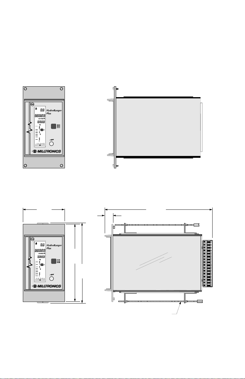
RACK MOUNT
The HYDRO+ rack mount version is a standard DIN 3U/14 HP, 4 rail plug-in unit, for a
standard 84 HP deep sub-rack.
PANEL MOUNT
72 mm
(2.9")
144 mm
(5.7")
150 mm
(5.9")
slip on mounting bracket top & bottom
screws to be tightened to no more than
PL-507 10
16 mm
(0.6")
1 inch / lb. torque.
201 mm
(7.9")
Page 11
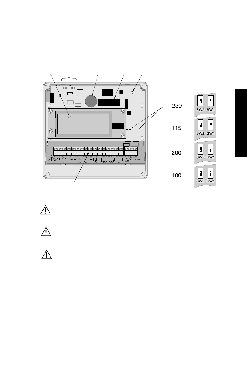
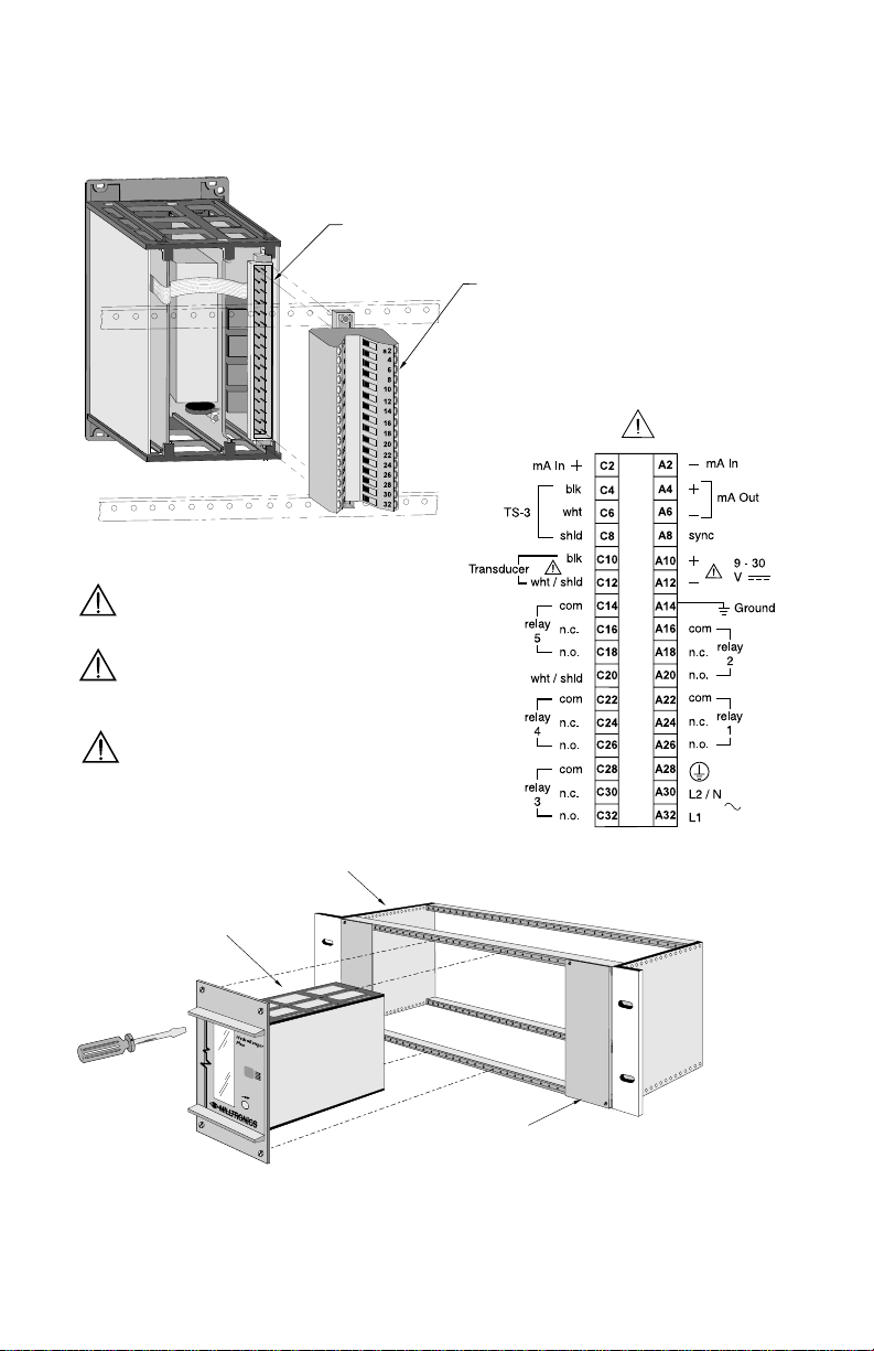
MOUNTING
WALL MOUNT
Voltage Selection
display
terminal block
scope
connection
clock module
EPROM
board A
Supply
Voltage
(ac)
All field wiring must have insulation suitable for at least 250 V .
Hazardous voltage present on transducer terminals during operation.
Voltage
Selection
Switches
INSTALLATION
dc terminals shall be supplied from an SELV source
in accordance with IEC 1010-1 Annex H.
Relay contact terminals are for use with equipment having no accessible
live parts and wiring having insulation suitable for at least 250 V.
The maximum allowable working voltage between
adjacent relay contacts shall be 250 V.
PL-507 11
Page 12
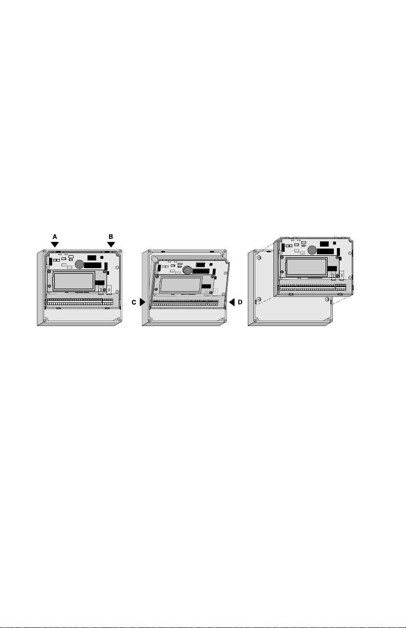
Installation
The HYDRO+ wall mount version enclosure design permits quick electronic package
removal for enclosure drilling and mounting.
1. Remove the HYDRO+ enclosure lid (4 captivated screws).
2. With the enclosure upright, press down enclosure TABS A and B.
3. Push in on TABS C and D to release the electronics package.
4. Drill sufficient holes for cable / conduit entry in the enclosure bottom.
5. Fasten the enclosure to the mounting surface, (4 predrilled screw holes).
6. Attach the conduit / cable hubs to the enclosure. (Do not apply undue force.)
7. Snap the electronics package back into the enclosure.
PL-507 12
Page 13
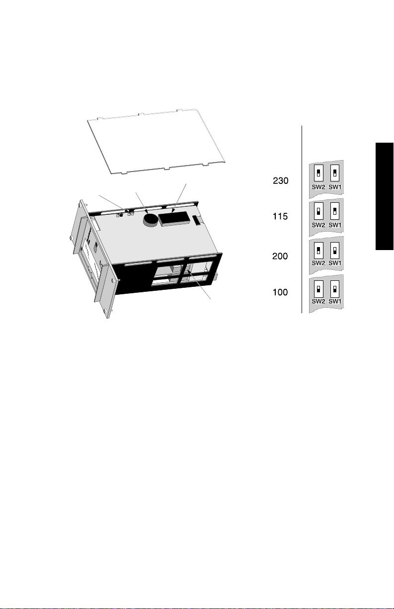
RACK MOUNT
Voltage
Selection
Switches
Voltage Selection
1. Set the voltage switches.
Supply
Voltage
(ac)
scope
connections
clock module
EPROM
voltage
selection
switches
INSTALLATION
PL-507 13
Page 14
Installation
1. Slide the Hydro+ into the sub-rack, aligning the connector with the
rail mounted terminal block.
connector,
2 row form D male 32 way, per DIN41612
terminal block,
2 row form D female 32 way,
per DIN41612
All field wiring must have insulation
suitable for at least 250 V .
Hazardous voltage present on transducer
terminals during operation.
dc terminals shall be supplied
from an SELV sourcein
accordance with IEC 1010-1
Annex H.
84 HP (19") sub-rack
HYDRO+
DIN 3U/14 HP
plug-in unit
blanking panels must
cover any unused slots
2. Push the Hydro+ into the sub-rack until the HYDRO+ front
cover is snug to the front rails.
3. Tighten the 4 captivated screws to secure the HYDRO+ in place.
PL-507 14
Page 15
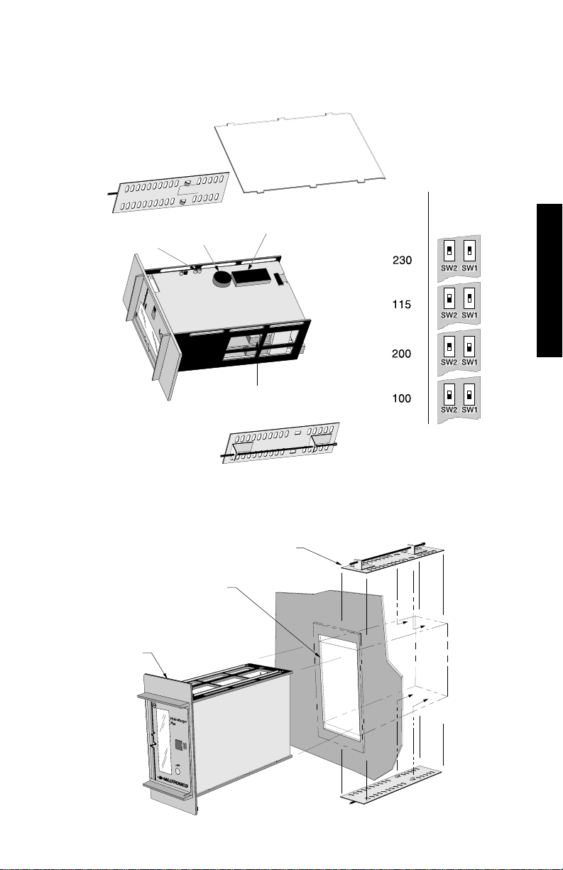
PANEL MOUNT
Voltage
Selection
Switches
Supply
Voltage
(ac)
Voltage Selection
1. Set the voltage switches.
scope
connections
clock module
EPROM
voltage
selection
switches
Installation
1. Slide the HYDRO+ through the panel cut-out.
2. Assemble mounting brackets to the HYDRO+ chassis by hooking them into
the top and bottom
mounting bracket
(top & bottom)
cut-out dimension
68 + 0.7 mm x 138 + 1.0 mm
(2.68 + 0.03" x 5.43 + 0.04")
INSTALLATION
DIN 43700
72 x 144
PL-507 15
Page 16
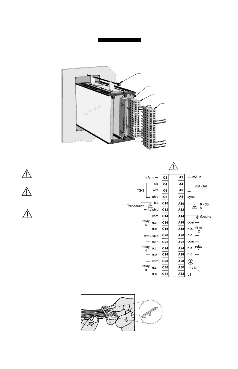
3. Tighten mounting bracket clamping screw (top & bottom)
terminal block ‘A’
4. Plug terminal blocks ‘A’ and ‘C’ into corresponding connector sockets,
prewired by customer (refer to \ Rack and Panel Mount).
INTERCONNECTION
clamping screw
connector
terminal block ‘C’
All field wiring must have insulation
suitable for at least 250 V .
Hazardous voltage present on transducer
terminals during operation.
dc terminals shall be supplied
from an SELV source in
accordance with IEC 1010-1
Annex H.
Use the tool provided
to open terminals for
insertion of wires.
PL-507 16
Page 17
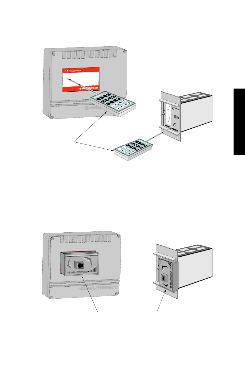
PROGRAMMER
Rack or Panel Mount
Rack or Panel Mount
Wall Mount
Programmer
The hand held programmer is aimed at the receiver as depicted, while the
keys are pressed.
INSTALLATION
COMVERTER (optional)
The ComVerter is pressed into the docking area as depicted and held in place
by its pressure tabs.
Refer to Dolphin instruction manual, for interconnection details.
PL-507 17
Wall Mount
ComVerter
Page 18
INTERCONNECTION
Milltronics transducer,
see Specifications
Milltronics TS-3
temperature sensor
(optional)
Verify all HYDRO+ system components have been installed in accordance with the
associated product instruction manuals.
Connect all cable shields to the HYDRO+ shield connections. To avoid differential
ground potentials, do not connect cable shields to ground (earth) elsewhere. Insulate
(tape) cable shields at all shield junctions to prevent ground loops
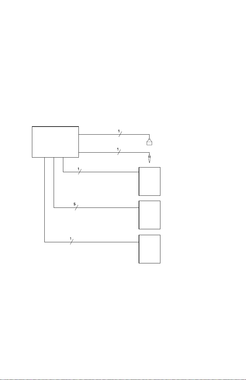
SYSTEM DIAGRAM
HydroRanger
Plus
mA output
customer
device
relay output
customer alarm, pump
or control device
mA input
PL-507 18
customer
device
Page 19

TRANSDUCER
#1 #2
to transducers
Run the transducer cable in grounded metal conduit, separate from other wiring,
(except TS-3 temperature sensor wiring, if applicable).
Typically, one transducer is used. However, if differential or average level monitoring
is required, 2 transducers are used.
Wall Mount
Single Transducer
to transducer
Rack or Panel Mount
Single Transducer
to
transducer
blk
wht
See transducer
instructions for
wiring details.
to
transducer
#1
to
transducer
#2
Dual Transducer
INSTALLATION
Dual Transducer
jumper
blk
blk
wht
Hazardous voltage present on transducer terminals during operation.
PL-507 19
Page 20

TEMPERATURE SENSOR
All Milltronics Echomax and ST-H transducers have an internal temperature sensor.
For optimum accuracy, use a separate TS-3 temperature sensor if:
» the transducer is exposed to direct sunlight (or other radiant heat source),
» the transducer connected is not an Echomax or ST-H, or
» the transducer face and monitored surface temperature differs.
» faster response to temperature changes are required.
TECHNICAL REFERENCE
(See TECHNICAL REFERENCE Sound Velocity).
Wall Mount Rack or Panel Mount
blk
wht
to optional TS-3
to optional TS-3
See TS-3 instructions for wiring detail.
Use a TS-3 temperature sensor only. Don’t jumper unused TS-3 terminals.
PL-507 20
Page 21
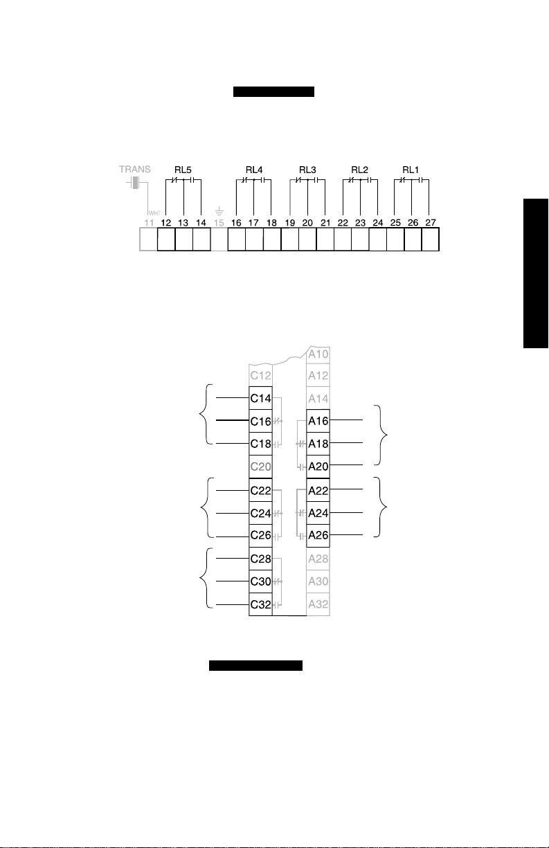
RELAYS
n. o.
Connect, alarm, pump, and/or control devices, to the HYDRO+ relays, after RUN
mode operation is verified. (See for connection details).
APPLICATIONS
Wall Mount
Rack or Panel Mount
com
relay 5
n. c.
n. o.
com
n. c.
relay 2
INSTALLATION
com
n. c.
n. o.
relay 1
relay 4
com
n. c.
n. o.
com
relay 3
n. c.
n. o.
See for relay ratings.
SPECIFICATIONS
Relays are shown in the alarm on / pump off / power off / de-energized position.
PL-507 21
Page 22
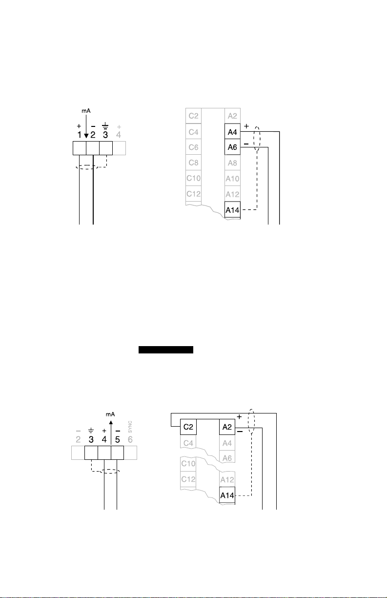
mA OUTPUT
The HYDRO+ mA output may be used to operate a variety of control/monitoring
devices (1000 Ω max. load), providing 300 Vac continuous isolation.
Wall Mount
mA out
Rack or Panel Mount
mA out
mA output to customer instrumentation, ground shield at one end only.
mA INPUT
If HYDRO+ features are required based upon measurements obtained from another
level monitor, connect the level monitor mA output, to the HYDRO+ mA input
terminals. Most HYDRO+ display, relay and mA output features may be used based
upon the measurements provided by the auxiliary level monitor.
If this feature is used, refer to Transducer (P004) and mA Input
PARAMETERS
Parameters (P250, P251, and P252).
Wall Mount
Rack or Panel Mount
mA input
mA input proportional to level, ground shield at one end only.
PL-507 22
mA input
Page 23
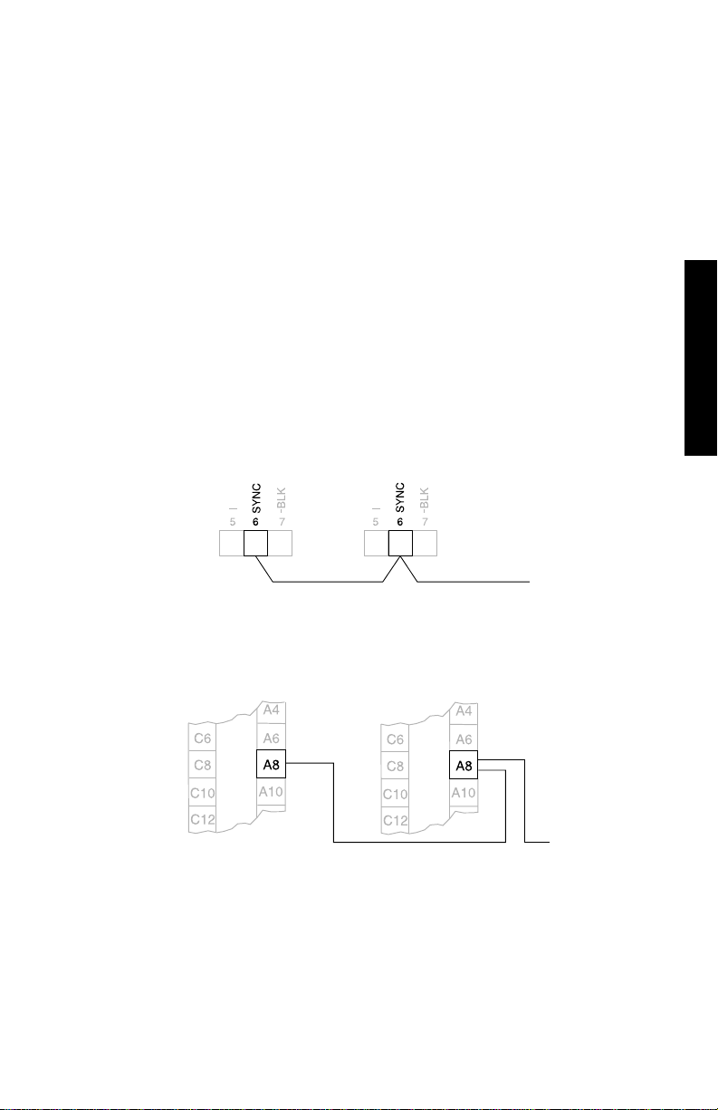
LEVEL SYSTEM SYNCHRONIZATION
to next
device
When multiple ultrasonic level monitors are installed within a single plant/facility,
ensure the transducer cable(s) of each system are run in separate grounded metal
conduits. Otherwise, synchronize the level monitors.
When level monitors are synchronized, no unit can transmit while another is awaiting
echo reception.
To synchronize the HYDRO+ with a DPL+, XPL+, and/or another HYDRO+...
1. Mount the level monitors together in one cabinet.
2. Use a common power (mains) supply and ground (earth) for all units.
3. Interconnect the SYNC terminals of all level monitors.
Wall Mount
INSTALLATION
Rack or Panel Mount
HYDRO +
# 1
HYDRO +
# 1
HYDRO +
# 2
to next
device
HYDRO +
# 2
To synchronize the HYDRO+ with other Milltronics
ultrasonic level monitors contact Milltronics
or your local distributor.
PL-507 23
Page 24
POWER
The HYDRO+ uses 100, 115, 200, or 230 Vac or 9 to 30 Vdc power. If ac and dc
power are supplied, the HYDRO+ draws power from the ac supply. In the event of an
ac power interruption, the dc supply is used until ac power is restored.
IMPORTANT!
Before applying ac power (mains), ensure the correct voltage is selected!
Never operate the HYDRO+ with the enclosure lid open,
or with the ground (earth) wire disconnected!
Before applying power to the HYDRO+ for the first time,
ensure any connected alarm/control equipment is disabled
until satisfactory system operation and performance is verified!
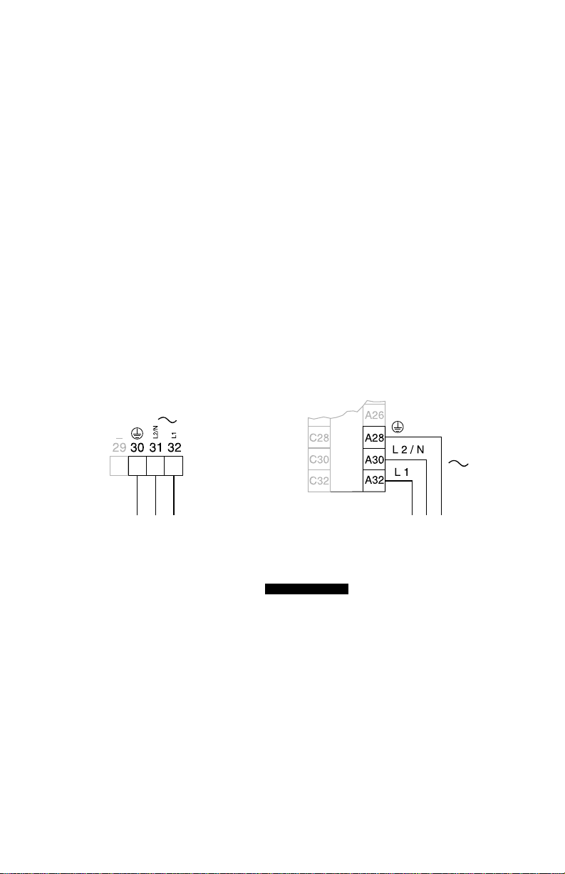
AC SUPPLY WIRING
Wall Mount
to ac supply
Set voltage selection switches per Mounting instructions.
Rack or Panel Mount
to ac supply
INSTALLATION
PL-507 24
Page 25
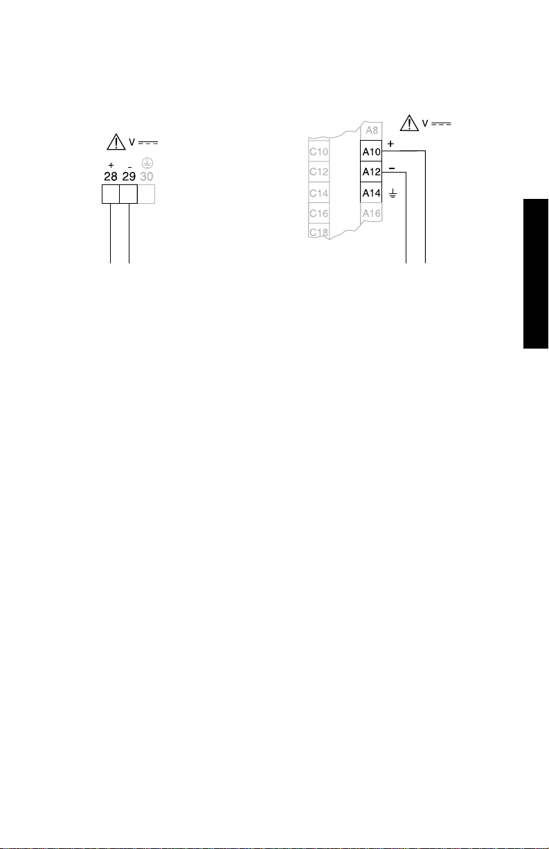
DC SUPPLY WIRING
Rack or Panel Mount
to dc supply
Wall Mount
to dc supply
Negative dc input (A12) is tied to earth (A14).
INSTALLATION
Customer voltage supply 9 to 30 V dc.
The equipment must be protected by a 15 A fuse or circuit
breaker in the building installation.
A circuit breaker or switch in the building installation, marked
as the disconnect switch, shall be in close proximity to the
equipment and within easy reach of the operator.
PL-507 25
Page 26

PL-507 26
Page 27

PROGRAMMING
Those not previously familiar with the HYDRO+, may wish to use the step by step
initial start up procedure illustrated in the HYDRORANGER PLUS QUICK START
GUIDE provided. Then, reference to the remainder of this instruction manual is only
necessary if operation modification is required.
All programmable features are identified by a Parameter Number, which has a preset
Parameter Value. Programming is accomplished by altering the Parameter Value of
specific Parameter Numbers to obtain the RUN mode operation desired.
When applicable, the Point Number to be affected, must be identified before the
Parameter Value is altered.
See APPLICATIONS for common HYDRO+ programming requirements. If more
APPLICATIONS
detailed parameter information is required, see PARAMETERS .
To enable the programmer
interface of the HYDRO+
rack or panel mount version,
press the key on the
front panel.
Program enable is confirmed
by the icon appearing in
the display. To disable
programming, press again.
Program disable is confirmed by
absence of the icon in the
display. Disable all nearby units
to avoid inadvertent programming.
PARAMETERS
PROGRAMMING
PROGRAM MODE ENTRY
Upon power application, RUN mode operation begins. To enter the program mode,
hold the programmer within 0.3 m (1 ft) of the
display window and,
When the program mode is entered, all operating data is retained in memory.
Alarm relay status and mA output values are "held" at "last known" values and
control relays are de-energized (unless affected by a parameter alteration
or is pressed), until the RUN mode is re-entered. The RUN mode is
automatically re-entered if the HYDRO+ is left unattended in the program
mode for an extended period (approximately 5 minutes).
PL-507 27
Page 28
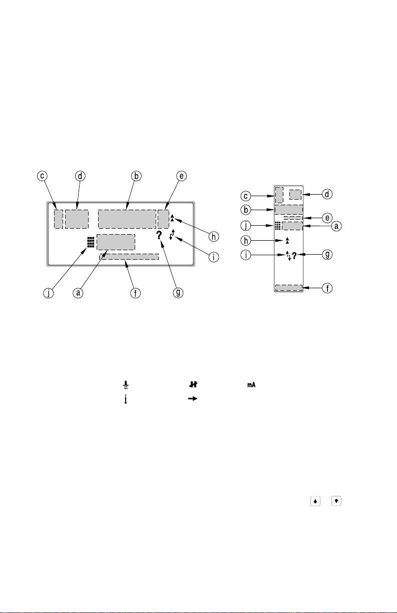
DISPLAY
In the program mode, the Parameter Number, Parameter Value (and Point Number if
applicable) may be viewed (as well as numerous other programming indicators).
Note that some indicators are specific to certain programming conditions and
therefore,
e.g. The Transducer Point Number is only displayed when Differential or Average
all indicators are not displayed at any given time.
level monitoring is selected, (requiring programming for 2 transducers).
wall mount rack or panel mount
a) Parameter Number (programmable feature accessed).
b) Parameter Value (setting for the Parameter Number displayed).
c) Point Type: transducer relay analog output
temperature index
d) Point Number (of the Point Type accessed).
e) Units (the Parameter Value is displayed in: m, cm, mm, ft, in, or %).
f) Relay Number (programmed for RUN mode operation).
g) Invalid Entry (the Parameter Value is questionable, are you sure?).
h) Auxiliary Function (of the Parameter Number is accessed).
i) Scroll Access Tag (the Parameter Number may be scroll accessed, or ).
j) Program Mode On (is accessed, operation has ceased).
Wall Mount: Program Mode accessed.
Rack or Panel Mount: Programmer interface enabled / Program Mode accessed.
PL-507 28
Page 29
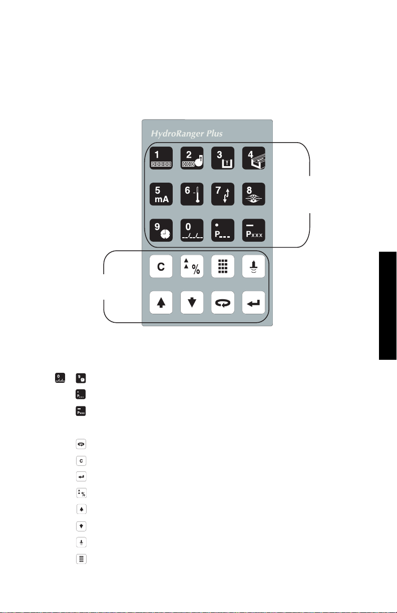
KEYPAD
These instructions ar e for hand programmer (keypad) use. Use the instructions
provided with the DOLPHIN interface package, if applicable.
Aim the HYDRO+ programmer infra-red transmitter at the HYDRO+ display within 0.3
m (12") of the display window. In the program mode, use the HYDRO+ programmer
keys to perform the following identified functions.
Numeric
Value
Keys
Function
Keys
KEY NUMERIC ENTRIES
input a numeric value into the display field accessed.
to
input a decimal point (moves TVT Pointers left).
input a negative value (moves TVT Pointers right).
FUNCTION
shift access to another display field.
delete the current field value (initiate a parameter reset).
store the field values in memory (complete a parameter reset).
switch to % or Units (access Auxiliary Parameter Function).
increase the current field value.
decrease the current field value.
fire the transducer to take an ultrasonic measurement.
enter the RUN mode.
PROGRAMMING
PL-507 29
98/03/19
Page 30
PARAMETER VALUE ALTERATION
In the program mode...
1. to underline the Parameter Number display field and...
a) key in the desired Parameter Number, (
b) as required (
(As preset, only Quick Start and altered parameters may be scroll accessed).
2. If the Point Number field is not displayed, proceed to step 3. Otherwise...
a) key in the desired Point Number, (
b) as required, (
To alter all Point Numbers at once, select Point Number 00.
3. With the Parameter Number (and Point Number if applicable) displayed...
key in the desired Parameter Value and,
or
to underline the Point Number display field and...
or
scroll access
scroll access
direct access
).
direct access
).
) or...
) or...
Record Parameter Value alterations on the appropriate
If Parameter Value alteration is not permitted, access the Lock parameter (P000)
and enter the security code, (see Programming Security).
PL-507 30
PROGRAMMING CHA
PROGRAMMING CHARTS
Page 31

SPECIAL PARAMETERS
Some Parameter Values are for display purposes only and cannot be operator
altered. These are referred to as
PARAMETERS
In the PARAMETERS section of this instruction manual, View Only parameters are
view only
parameters.
identified by a "(V)" beside the Parameter Number.
Many Parameter Values must be common for all Point Numbers. These are referred
global
to as
parameters.
When a global parameter is accessed, the Point Number display automatically
disappears. When a non-global parameter is accessed, the Point Number previously
selected is displayed.
In the parameters sections of this manual, Global parameters are identified by a "(G)"
beside the Parameter Number.
PARAMETER RESET FEATURES
To return an operator adjusted Parameter Value to the preset value, with the
appropriate Parameter Number (and Point Number if applicable) displayed...
To reset all parameters to preset values, see Master Reset (P999).
Perform a Master Reset (P999) to preset all parameters to "original"
values before initial system installation, following an EPROM
replacement, or whenever complete reprogramming is required.
PARAMETERS
PROGRAMMING
PL-507 31
Page 32

PROGRAMMING SECURITY
All operator programming is retained in non-volatile memory, immune to power
interruptions. When programming is complete, the programmer may be locked away
to prevent inadvertent programming alteration. As well, the Lock (P000) parameter
may be used.
PL-507 32
Page 33

OPERATION
With parameter alteration complete, the HYDRO+ may be put into operation.
Once put into operation (the RUN mode is entered), the HYDRO+ continues to
operate unattended, indefinitely. However, numerous RUN mode features are
available for aquiring specific operating information without removing the HYDRO+
from service.
RUN MODE ENTRY
The HYDRO+ automatically starts up in the RUN mode when power is applied.
After a programming alteration, do not use the HYDRO+ to
operate alarms or controls until system programming and
To enter the RUN mode from the Program mode...
"----" is displayed briefly while the Reading is calculated and verified.
When complete, the Reading and other data is displayed; the mA output
value and relay status are immediately updated accordingly.
(During "differential" or "average" Operation (P001 = 4 or 5), the display scrolls
sequentially through Point Numbers 1, 2, and 3. Point Number 3 represents the
difference between or average of Point Numbers 1 and 2).
performance is verified.
If the HYDRO+ is left unattended in the Program mode
for more than 5 minutes, the RUN mode
is automatically entered.
PL-507 33
OPERATION
Page 34

DISPLAY
In the RUN mode, the following values and indicators may be observed.
Note that many indicators are specific to certain operating conditions and
therefore,
all indicators are not displayed at any given time.
wall mount rack or panel mount
1. the current display pertains to a Transducer measurement.
2. Transducer Number 1, 2, or Result 3 (DPD or DPA operation only).
3. Reading resulting from Operation selected, (error message).
4. the Reading is in m, cm, mm, ft, in or %.
▲
5. = HI alarm, = HI HI alarm.
▲
▲
6. Bar graph representation of level from 0 to 100% (absolute).
7. monitored surface is rising (nearer transducer).
8. monitored surface is falling (farther from transducer).
▼
9. = LO alarm, = LO LO alarm.
10. = Relay # programmed.
¡
l
¡
11. = pump, control, or alarm on.
▼
▼
12. Auxiliary Reading (see Keypad for selection).
13. = Normal operation.
14. = Failsafe operation.
15. programmer interface enable (rack or panel mount only)
PL-507 34
Page 35

KEYPAD
Auxiliary Reading Keys
In the RUN mode, the following programmer keys perform the identified functions.
Function Keys
KEY READING
"8 Digit Totalizer" ("OCM" or "PT" Operation, P001 = 6 or 7)
AUXILIARY READINGS
"Pump Running Time" (key in Pump Number, hold for Starts)
"Head" (OCM Operation, P001 = 6)
"Flow based on Head" (OCM Operation, P001 = 6)
"mA Output Value"
"Temperature" (air in °C)
"Rate of Change" (in Units/minute)
"Failsafe Time Left" (in percent)
"Time" (HH:MM, 24 hour format)
"Date" (MM:DD, of the current year)
"Parameter Value" (key in Parameter Number)
"Material Level" (may be altered via P731)
"Distance" (surface to transducer face)
OPERATION
PL-507 35
FUNCTION
initiate program mode access (see )
toggle between Units and % (complete program mode access)
stop/start the Point Number auto display scroll
select the next Point Number (stop the display scroll)
select the previous Point Number (stop the display scroll)
Page 36

SYSTEM PERFORMANCE EVALUATION
1. to enter the RUN mode.
If a pump or control is ON, the corresponding relay is energized. If an alarm is ON, the
relay is de-energized.
2. to display the Reading in
%
(percent of Span, P007).
OPERATION LEVEL SPACE or DISTANCE
Empty to Full = 0 to 100% 100 to 0%
3. to observe the current mA output value (Auxiliary Reading).
OPERATION LEVEL SPACE or DISTANCE
Empty to Full = 4-20 mA 20-4 mA
4. and then or to observe accumulated
pump running hours
5. and hold the or key (for 5 seconds) to
observe the number of accumulated pump starts
2
for pumps 1 to 5 respectively.
2
for
pump 1 to 5 respectively.
6. to observe the
Failsafe Time Left
(in %) to failsafe activation.
When the Reading is updated, this value (Auxiliary Reading) resets to
100 and begins to decrease until the next valid measurement is made.
If the Failsafe Time Left reaches 0, "LOE" flashes in the Reading display.
1
less than 0.3m (1 ft) cannot be reliably measured; a 0% Reading or 4 mA
cannot be achieved during "distance" Operation.
2
if the associated relay is programmed for a pump control function.
1
1
PL-507 36
Page 37

PERFORMANCE TEST RESULTS
Monitor system performance carefully, under all anticipated operating conditions.
A. When the HYDRO+ performs exactly as required, programming is complete.
B. If alternate Reading units, failsafe action, relay, or mA output operation is
desired, proceed to APPLICATIONS and/or PARAMETERS as required.
C. Should system performance not meet installation requirements, (or the "LOE"
display persists after start up), proceed to TROUBLESHOOTING .
If all operating conditions cannot be observed during the System Performance
Evaluation, refer to PARAMETERS Reading Measurement (P920). Perform a
PARAMETERS
Reading Measurement simulation to verify programming.
Conduct a System Performance Evaluation following any installation modification or
programming (parameter) alteration.
APPLICATIONS
PARAMETERS
TROUBLESHOOTING
PL-507 37
OPERATION
Page 38

MAINTAINING OPERATION
With programming complete, record all parameter alterations.
a) If the keypad programmer is used, enter the program mode and scroll
access altered parameters (skipping parameters left at preset values).
Record parameter alterations on the PROGRAMMING CHARTS.
b) If the DOLPHIN interface package is used, refer to the associated
instructions to record all operator programming.
For normal operation, return to the RUN mode. The HYDRO+ will perform reliably,
requiring little or no maintenance.
Connect (or enable) process control/alarm equipment to the
HYDRO+ only after satisfactory performance is verified for
all possible operating conditions.
PROGRAMMING CHARTS
PL-507 38
Page 39

APPLICATIONS
The following examples illustrate how easily the HYDRO+ may be programmed to
meet specific application requirements.
While your installation may not match these examples exactly, by reviewing the
closest example (or combination of examples), the relationship between HYDRO+
features and your process measurement requirements may be more easily identified.
In every case, refer to General Application. This example defines the minimum
programming required for any application. Then refer to the applicable "add on"
examples for programming information specific to your application.
If additional parameter detail is required, (than provided in these examples), see
PARAMETERS
PARAMETERS for complete parameter definitions.
Ensure all alarms and controls are disabled until all application programming is
complete and satisfactory RUN mode performance is verified.
1. General Application (common programming to all applications).
2. Wet Well Control add on (combine with example 1).
3. Reservoir Control add on (combine with example 1).
4. Screen Rake Control add on (combine with example 1).
5. Penstock Control add on (combine with example 1).
6. General Alarm add on (combine with example 1).
7. Volume Calculation add on (combine with example 2 or 3).
8. Pumped Volume Calculation add on (combine with example 2 or 3 and 7).
9. OCM Flow Calculation add on (combine with example 1).
10. Failsafe Operation add on (combine with example 1 to 5).
PL-507 39
APPLICATIONS
Page 40

GENERAL APPLICATION
PARAMETER PRESET OPERATION
P001 Operation 3 = distance display Reading referenced to transducer face
P002 Material 1 = liquid anticipates echoes from a flat reflective surface
P003 Response 2 = 1 m/min typical liquid surface rate of change
P004 Transducer 100 = ST-H compensates for temperature variation
P005 Units 1 = metres displays all linear dimensions in metres
P006 Empty 8.000 0% level bar graph reference point.
P007 Span 8.000 100% level bar graph reference point.
P008 Date YY.MM.DD automatic leap year adjustment
P009 Time HH.MM.SS 24 hour format
If power is applied before any programming is performed, the HYDRO+ starts running,
using the parameter preset values. As long as the transducer connected has an
internal temperature sensor and a maximum range of 15 m (50 ft) or less, the preset
Transducer (P004) value is suitable for operator orientation with HYDRO+ operation.
If "Error" and the transducer terminal numbers are displayed, the transducer does not
have an internal temperature sensor. See Transducer (P004) options.
The HYDRO+ operates like an ultrasonic tape measure, displaying distance from the
transducer face to the surface monitored.
PL-507 40
Page 41

PARAMETER VALUE OPTIONS
(use to key in ":".
Operation 1 = "level", Full = 100% Reading = 20 mA (most common)
(P001) = 2 = "space", Empty = 100% Reading = 20 mA (less common)
3 = "distance", (references measurements to transducer face)
4 = "DPD", (displays differential level, 2 transducers required)
5 = "DPA", (displays average level, 2 transducers required)
6 = "OCM", (calculates flowrate for head and total flow volume)
7 = "PT", (calculates total pumped volume)
Material 1 = "liquid", flat perpendicular reflective surface (most common)
(P002) = 2 = "solid", angled rough reflective surface (for heaping solids)
Measurement 1 = "0.1 m/min", very slow moving surface (less common)
Response 2 = "1.0 m/min", typical liquid surface (usual setting)
(P003) = 3 = "10 m/min", very fast moving surface (less common)
Transducer 0 = "out-of-service"
(P004) 1 = "ST-25"
2 = "ST-50"
100 = "ST-H"
101 = "XCT-8" Enter the appropriate transducer type
102 = "XPS-10"
103 = "XCT-12"
104 = "XPS-15"
250 = "mA input"
Units 1 = "metres"
(P005) = 2 = "centimetres"
Empty
(P006) = "0.000" to "9999" Enter value in P005 Units
Span
(P007) = "0.000" to "9999" Preset by P006, change if desired.
Date
(P008) = "00:01:01" to "99:12:31"
Time
(P009) = "00:00:00" to "23:59:59"
With General Application programming complete, a System Performance Evaluation
OPERATION
(see OPERATION ) is recommended before proceeding to the following Application
programming examples.
PL-507 41
3 = "millimetres" Enter the linear dimension units desired
4 = "feet"
5 = "inches"
APPLICATIONS
Page 42

WET WELL CONTROL (Pump Down)
Typically, wet wells are used to temporarily hold storm and/or waste water. When the
surface reaches a high level setpoint, the wet well is pumped down. The discharge
goes on to another wet well or directly to the treatment facility.
The HYDRO+ provides wet well control with only minimal application programming.
For the following example, we’ll assume Empty (P006) was set from the transducer
face to the wet well floor. (To monitor wet well overflow, see the note at the end of the
OCM Application example).
(If the transducer cannot be located to avoid acoustic beam interference from the
pumps, set Empty (P006) from the transducer face to the top of the pump(s).
FULL
HI Alarm On
HI Alarm Off
Start Pump 1
Start Pump 2
Pump Down,
2 Alternate
Assist Pumps
Stop Pumps
Lo Alarm Off
Lo Alarm On
EMPTY
RELAY INTERCONNECTION
The relay contact illustrations adjacent to the HYDRO+ relay terminals are shown in
the power off, de-energized, alarm on, pump off condition.
Connect the HYDRO+ relays as follows:
RL1 to Pump 1 control (energized = pump on, de-energized = pump off)
RL2 to Pump 2 control (energized = pump on, de-energized = pump off)
RL3 to Hi Alarm indicator (energized = alarm off, de-energized = alarm on)
RL4 to Lo Alarm indicator (energized = alarm off, de-energized = alarm on)
RL5 not used
PL-507 42
Page 43

PROGRAMMING
Set Relay Set Up to "Wet Well 1" (P100=1) to preset relays as follows.
PARMETER RL#1 RL#2 RL#3 RL#4 RL#5
P111 Relay Function 52 52 1 1 0
P112 Relay A Setpoint 70% 80% 90% 10% ---P113 Relay B Setpoint 20% 20% 85% 15% ---For one pump, set the RL#1 or RL#2 Relay Function to "off" (P111 = 0).
For 3 or more pumps (5 max.), choose the relay(s) to be used and program P111,
P112 and P113 similar to RL# 1 and RL# 2 (but stagger the P112 setpoints).
OPERATION
By level (as indicated on bar graph) for 2 pumps...
1. Pump controls are operated as "alternate duty assist" (P111 = 52):
NORMAL OPERATION
a) Pump 1 (lead pump) starts at 70%.
b) Pump 1 stops at 20%, shift setpoints (lead) to next pump.
PEAK DEMAND OPERATION
a) Pump 1 (lead pump) starts at 70%.
b) Pump 2 (next pump) starts at 80%.
c) Pump 1 and 2 stop at 20%, shift lead to next pump.
2. Alarms indicate control/pump malfunction (or excessive/insufficient capacity).
a) HI alarm "on" at 90%, off at 85%.
b) LO alarm "on" at 10%, off at 15%.
c) Both alarms "on" = HYDRO+ power interruption.
3. Use the 4-20 mA output if desired...
a) proportional to level if Operation = "level" (P001 = 1).
b) inversely proportional to level if Operation = "space" (P001 = 2).
4. To view pump information in the RUN mode...
a) and then the pump # (to view the pump running hours total).
b) and hold the pump # (to view the number of pump starts total)
PL-507 43
APPLICATIONS
Page 44

RESERVOIR CONTROL (Pump Up)
Empty
Typically, reservoirs are used to temporarily hold processed water. When the water
surface reaches a low level setpoint, the reservoir is pumped up.
The HYDRO+ provides reservoir control with only minimal application programming.
For the following example, we’ll assume Empty (P006) was set from the transducer
face to the reservoir bottom.
FULL
HI Alarm On
HI Alarm Off
Stop Pumps
Start Pump 1
Start Pump 2
Lo Alarm Off
Lo Alarm On
RELAY INTERCONNECTION
The relay contact illustrations adjacent to the HYDRO+ relay terminals are shown in
the power off, de-energized, alarm on, pump off condition.
Connect the HYDRO+ relays as follows:
RL1 to Pump 1 control (energized = pump on, de-energized = pump off)
RL2 to Pump 2 control (energized = pump on, de-energized = pump off)
RL3 to Hi Alarm indicator (energized = alarm off, de-energized = alarm on)
RL4 to Lo Alarm indicator (energized = alarm off, de-energized = alarm on)
RL5 not used
PL-507 44
Page 45

PROGRAMMING
Set Relay Set Up to "Reservoir 1" (P100=3) to preset relays as follows.
PARAMETER RL#1 RL#2 RL#3 RL#4 RL#5
P111 Relay Function 52 52 1 1 0
P112 Relay A Setpoint 30% 20% 90% 10% ---P113 Relay B Setpoint 80% 80% 85% 15% ---For one pump, set the RL#1 or RL#2 Relay Function to "off" (P111 = 0).
For 3 or more pumps (5 max.), choose the relay(s) to be used and program P111,
P112 and P113 similar to RL# 1 and RL# 2 (but stagger the P112 setpoints).
OPERATION
By level (as indicated on bar graph) for 2 pumps...
1. Pump controls are operated as "alternate duty assist" (P111 = 52):
NORMAL OPERATION
a) Pump 1 (lead pump) starts at 30%.
b) Pump 1 stops at 80%, shift setpoints (lead) to next pump.
PEAK DEMAND OPERATION
a) Pump 1 (lead pump) starts at 30%.
b) Pump 2 (next pump) starts at 20%.
c) Pump 1 and 2 stop at 80%, shift lead to next pump.
2. Alarms indicate control/pump malfunction (or excessive/insufficient capacity).
a) HI alarm "on" at 90%, off at 85%.
b) LO alarm "on" at 10%, off at 15%.
c) Both alarms "on" = HYDRO+ power interruption
3. Use the 4-20 mA output if desired...
a) proportional to level if Operation = "level" (P001 = 1).
b) inversely proportional to level if Operation = "space" (P001 = 2).
4. To view pump information in the RUN mode...
and then the pump # (to view the pump running hours total)
and hold the pump # (to view the number of pump starts total)
PL-507 45
APPLICATIONS
Page 46

RAKE CONTROL (Differential Level)
Typically a water purification process has a screen on the inlet side to filter solids from
entering the process. Should the screen become blocked, and inflow sufficiently
reduced, process efficiency can often be compromised.
The HYDRO+ provides screen rake control with only minimal application
programming. For the following example, we’ll assume Operation was set for
"differential" (P001 = 4) and Empty (P006) was set from the transducer face to the
channel bottom for both transducer 1 and transducer 2.
RAKE CONTROL
RELAY INTERCONNECTION
The relay contact illustrations adjacent to the HYDRO+ relay terminals are shown in
the power off, de-energized, alarm on, control off condition.
Connect the HYDRO+ relays as follows:
RL1 to Rake control (energized = rake on, de-energized = rake off)
RL2 to Hi Alarm (Point 1) (energized = alarm off, de-energized = alarm on)
RL3 to Lo Alarm (Point 2) (energized = alarm off, de-energized = alarm on)
RL4 to Hi Alarm (Point 3) (energized = alarm off, de-energized = alarm on)
RL5 to transducers See INSTALLATION Interconnection\Transducer
PL-507 46
INSTALLATION
Page 47

PROGRAMMING
Set Relay Set Up to "Rake Control" (P100=5) to preset relays as follows.
PARAMETER RL#1 RL#2 RL#3 RL#4 RL#5
P110 Relay Allocation 31231
P111 Relay Function 50 1 1 1 49
P112 Relay A Setpoint 80% 90% 10% 90% ---P113 Relay B Setpoint 20% 85% 15% 85% ----
OPERATION
By level (as indicated by the Point Number bar graphs)...
1. The rake control:
a) is turned "on" when Point # 3 = 80%.
b) is turned "off" when Point # 3 = 20%.
2. Alarms indicate critical operating conditions.
a) Hi Alarm (Point 1) = high channel inflow (on 90%, off 85%).
b) Lo Alarm (Point 2) = low channel outflow (on 10%, off 15%).
c) Hi Alarm (Point 3) = rake malfunction (on 90%, off 85%).
d) All Alarms = HYDRO+ power interruption.
3. The 4-20 mA output is proportional to level on Point 1. If desired, set the mA
Allocation for Point 2 (P202 = 2) or for differential Point 3 (P202 = 3).
PL-507 47
APPLICATIONS
Page 48

PENSTOCK CONTROL
A
penstock
open channel flowrate. In some cases, penstock control is used to limit storm flow
conditions through the channel by diverting excess (storm condition) flow to a
temporary holding vessel.
To monitor open channel flow downstream from a penstock, see the note at the end
of the OCM application example.
The HYDRO+ provides time step penstock control based on open channel level with
only minimal application programming. For the following example, we’ll assume
Operation was set for "level" (P001 = 1) and Empty (P006) was set from the
transducer face to the channel bottom.
(motorized liquid flow control gate) is often used to control and maintain
penstock
storm
spillway
transducer
RELAY INTERCONNECTION
The relay contact illustrations adjacent to the HYDRO+ relay terminals are shown in
the power off, de-energized, alarm on, control off condition.
Connect the HYDRO+ relays as follows:
RL1 to "OPEN" control (energized = open penstock per P112,P114 and P115)
RL2 to "CLOSE" control (energized = close penstock per P112, P114 and P115)
RL3 to Hi Alarm (energized = alarm off, de-energized = alarm on)
RL4 to Lo Alarm (energized = alarm off, de-energized = alarm on)
RL5 not used
PL-507 48
Page 49

PROGRAMMING
GENERAL
P001 Operation = 1 (level)
P006 Empty = 1.7 m (e.g. Transducer to channel bottom)
P007 Span = 1.3 m (e.g. Channel bottom to highest head)
RELAYS
Set Relay Set Up to "off" (P100=0, preset) prior to relay programming.
PARAMETER RL#1 RL#2 RL#3 RL#4 RL#5
P111 Relay Function 63 63 1 1 0
*
P112 Relay A Setpoint
P113 Relay B Setpoint
P114 Relay C Setpoint
45% 55% 65% 35% ----
*
---- ---- 60% 40% ----
*
0.1 ---- ---- ---- ----
P115 Relay D Setpoint * 1 ---- ---- ---- ----
*
Relay Setpoints above are for illustration purposes only. Program Relay Setpoints
as required to satisfy individual application requirements.
OPERATION
By level (as indicated by the bar graph)...
1. The Penstock is:
a) driven more open for 0.1 minute at 45% level or less (RL1).
b) driven more closed for 0.1 minute at 55% level or more (RL2).
c) control operation is limited (P115) to every 1 minute (for stabilization).
d) both controls are held "off" if the level is between 45.01% and 54.99%.
2. Alarms indicate critical operating conditions.
a) Hi Alarm = close control malfunction (on 65%, off 60%)
b) Lo Alarm = open control malfunction (on 35%, off 40%)
c) Both Alarms = HYDRO+ power interruption
3. Use the 4-20 mA output if desired...
a) proportional to level if Operation = "level" (P001 = 1).
b) inversely proportional to level if Operation = "space" (P001 = 2).
PL-507 49
APPLICATIONS
Page 50

GENERAL ALARMS
HI Alarm On
Lo Alarm Off
HI Alarm Off
If relay operated controls are not required, the following general alarms may be added
to the general application programming.
Alarms (similar to controls) are always based on level regardless of the Operation
(P001) selected.
FULL
HI HI Alarm On
HI HI Alarm Off
RELAY INTERCONNECTION
The relay contact illustrations adjacent to the HYDRO+ relay terminals are shown in
the power off, de-energized, alarm on, control off condition.
Connect the HYDRO+ relays as follows:
RL1 to Hi Alarm (energized = alarm off, de-energized = alarm on)
RL2 to Lo Alarm (energized = alarm off, de-energized = alarm on)
RL3 to Hi Hi Alarm (energized = alarm off, de-energized = alarm on)
RL4 to Lo Lo Alarm (energized = alarm off, de-energized = alarm on)
RL5 not used
PL-507 50
Lo Alarm On
Lo Lo Alarm Off
Lo Lo Alarm On
EMPTY
Page 51

PROGRAMMING
RELAYS
Set Relay Set Up to "General Alarms" (P100 = 6) to preset relays as follows.
PARAMETER RL#1 RL#2 RL#3 RL#4 RL#5
P111 Relay Function 11110
P112 Relay A Setpoint 80% 20% 90% 10% ---P113 Relay B Setpoint 75% 25% 85% 15% ----
OPERATION
1. Alarms indicate critical operating conditions.
a) Hi Alarm = high level (on 80%, off 75%).
b) Lo Alarm = low level (on 20%, off 25%).
c) Hi Hi Alarm = higher level (on 90%, off 85%).
d) Lo Lo Alarm = lower level (on 10%, off 15%).
2. Use the 4-20 mA output if desired...
a) proportional to level if Operation = "level" (P001 = 1).
b) inversely proportional to level if Operation = "space" (P001 = 2).
PL-507 51
APPLICATIONS
Page 52

OCM (Open Channel Monitor) Flow and Total Calculation
Typically, a water treatment process has a free flowing open channel on the inlet side.
The channel is often restricted by a
head/flow relationship.
(See note at end of example for monitoring overflow from a wet well or flow
downstream from a Penstock).
The HYDRO+ provides OCM flow and totalized flow calculation with only minimal
application programming. Ensure Operation is set for "OCM" (P001 = 6) and Empty
(P006) is set from the transducer face to the channel bottom at the distance from the
PMD (if used) prescribed by the supplier.
RELAY INTERCONNECTION
The relay contact illustrations adjacent to the HYDRO+ relay terminals are shown in
the power off, de-energized, alarm on, control off condition.
Connect the HYDRO+ relays as follows:
RL1 As indicated by the alarm/control application example used.
RL2 As indicated by the alarm/control application example used.
RL3 As indicated by the alarm/control application example used.
RL4 As indicated by the alarm/control application example used.
RL5 to the remote totalizer (if used)
PMD
(Primary Measuring Device) having a known
PL-507 52
Page 53

PROGRAMMING
OCM
P600 PMD = 1 (preset, change to applicable PMD)
P601 Flow Exponent = 2.50 (preset, change per PMD used, P600 = 1 only)
P602 Flume Dimension D = 1 (preset, change per PMD used, P600 = 2 or 3)
P603 Max Head = Span (preset, change to actual head at Max Flow)
P604 Max Flow = 1000 (preset, change to flow at Max Head)
P605 Zero Head = 0.000 (preset, change to zero head distance above Empty)
P606 Time Units = 1 (preset, time portion of Max Flow)
P607 Flow Decimal = 3 (e.g. display value to 3 decimal places)
P610 Head Breakpoints = ---- (change to known flow heads; 32 max, P600 = 4 or 5)
P611 Breakpoint Flowrates = ---- (change to flow at P610 heads; P600 = 4 or 5)
P620 Low Flow Cutoff = 5% (preset, below this head, flow is not totalized
LCD TOTALIZER
0
P630 LCD Total Factor = 0 (preset, display in 1 x 10
Max Flow volume units)
P633 LCD Total Decimal = 3 (e.g. display value to 3 decimal places)
REMOTE TOTALIZER (optional)
P111 Relay Function = 40 (totalizer) for RL5
0
P640 Relay Total Factor = 0 (preset, pulse every 1 x 10
(P604) volume units)
P645 Relay On Time = 0.2 seconds (preset, adjust if necessary to suit totalizer)
OPERATION
1. Alarms and/or controls operate as programmed by other Application examples.
2. The totalizer relay energizes for (P645) seconds for every (P640) units.
3. The 4-20 mA output is proportional to flow.
4. to display 8 digit total flow volume.
5. to display head.
6. to display flowrate.
To monitor the overflow (through a weir) from a wet well, program the HYDRO+ as
indicated above, except program Empty (P006) and relays as illustrated in the Wet
Well Control application example.
To monitor flow downstream from a Penstock, program the HYDRO+ as
indicated above, except program relays as illustrated in the Penstock Control
application example.
PL-507 53
APPLICATIONS
Page 54

VOLUME CALCULATION
Universal
Linear
10 =
Sometimes, an indication of the liquid volume contained within a vessel, or remaining
vessel capacity is required.
The HYDRO+ provides volume calculation with only minimal application programming.
Ensure Empty (P006) is set from the transducer face to the vessel bottom and Span
(P007) is set from the vessel bottom to the vessel top.
1 =
2 =
3 =
flat level bottom
cone / pyramid bottom
or
A
parabola bottom
A
4 =
5 =
6 =
7 =
half sphere bottom
A
flat sloped bottom
or
A
flat ends
parabola ends
sphere
8 =
9 =
Universal
Curved
LA
RELAY INTERCONNECTION
Connect the HYDRO+ relays as indicated by the alarm/control example used.
Ensure the surface monitored is controlled from coming within 0.33 m (1.1 ft) of the
transducer face, (see INSTALLATION Transducer).
INSTALLATION
Volume calculation does not alter relay programming.
PL-507 54
Page 55

PROGRAMMING
VOLUME
P050 Tank Shape = 0 (preset, change to applicable shape)
P051 Max Volume = 100 (preset, display in %, other = volume of Span, P007).
P052 Tank Dimension A (required for Tank Shapes: P050 = 2,3,4,5, or 7).
P053 Tank Dimension L (required for Tank Shape P050 = 7)
P054 Level Breakpoint (32 max., required for Tank Shapes: P050 = 9 or 10).
P055 Breakpoint Volumes = volume associated with Level Breakpoints (P054).
OPERATION
1. Alarms and/or controls operate as programmed by other Application examples.
2. Use the 4-20 mA output if desired . . .
a) proportional to liquid volume if Operation = "level" (P001 = 1).
b) proportional to remaining capacity if Operation = "space" (P001 = 2).
PL-507 55
APPLICATIONS
Page 56

PUMPED VOLUME TOTAL
Remote Totalizer
Sometimes, an indication of the total liquid volume pumped from a wet well or into a
reservoir is required.
The HYDRO+ provides total volume pumped calculation with only minimal application
programming. Ensure Operation is set for "Pumped Total" (P001 = 7) and the Wet
Well or Reservoir Control and Volume Calculation application programming is
complete before proceeding.
(not supplied)
RELAY INTERCONNECTION
The relay contact illustrations adjacent to the HYDRO+ relay terminals are shown in
the power off, de-energized, alarm on, control off condition.
Connect the HYDRO+ relays as follows:
RL1 As indicated by the alarm/control application example used.
RL2 As indicated by the alarm/control application example used.
RL3 As indicated by the alarm/control application example used.
RL4 As indicated by the alarm/control application example used.
RL5 To the remote totalizer (if used)
PL-507 56
Page 57

PROGRAMMING
LCD TOTALIZER
P622 In/Out Correction = 1 (preset, auto total inflow/discharge adjust)
P630 LCD Total Factor = 0 (preset, display total in Max Volume units)
P633 LCD Total Decimal = 3 (e.g. display 3 decimal places)
REMOTE TOTALIZER (optional)
P111 Relay Function = 40 (totalizer) for RL5
0
P640 Relay Total Factor = 0 (preset, pulse every 1 x 10
Max Volume units)
P645 Relay On Time = 0.2 seconds (preset, adjust if necessary to suit totalizer)
OPERATION
1. Alarms and/or controls operate as programmed by other
Control Application programming examples.
2. The totalizer relay energizes for (P645) seconds for every (P640) volume units.
3. The 4-20 mA output is proportional to volume (per Volume Calculation).
4. to display 8 digit total volume pumped value.
5. To view pump information in the RUN mode...
and then the pump # (to view the pump running hours total)
and hold the pump # (to view the number of pump starts total)
PL-507 57
APPLICATIONS
Page 58

FAILSAFE OPERATION GENERAL
As preset, upon a loss of echo, the HYDRO+ Reading, alarm relays, and mA output
are held at last "known" values and pump/control relays are de-energized, until a valid
measurement is regained.
If desired, program the HYDRO+ to provide alternative display, relay and/or mA
output operation under loss of echo conditions to provide failsafe operation.
PROGRAMMING
1. Enter the
P071: HI = 100% bar graph level
2. Enter the Measurement Response for advance to the Failsafe Material Level.
P003 Response: 1 = 100 minute delay, advance at 0.1 metres/minute
3. To test failsafe operation (with the monitored surface still), disconnect the
transducer cable and ensure alarms/controls activate.
For more failsafe programming and operation information,
see PARAMETERS P003,P070,P071,P072,P129,P219,P700,P701.
Failsafe Material Level
LO = 0% bar graph level and or to access.
HOLd = last level (preset)
specific level = -50% to 150% of Span (P007) in Units or %.
2 = 10 minute delay, advance at 1 metre/minute
3 = 1 minute delay, advance at 10 metres/minute
PARAMETERS
(where alarms warn "unsafe" operation).
If any of these parameters are altered, retest Failsafe Operation.
PL-507 58
Page 59

WET WELL FAILSAFE
HI Alarm
HI Level
Fault
Detector
LO Level
Fault
Detector
OPERATION
For this example we’ll assume:
P001 Operation is set to "level" (P001 = 1).
P003 Measurement Response is set to "medium" (P003 = 2, preset).
P006 Empty is set for 6.000 metres.
P007 Span is set for 5.000 metres.
P071 Failsafe Material Level is set for "HI".
P100 Relay Set Up is set for Wet Well 1 (P100 = 1).
a) high alarm is to indicate failsafe operation.
b) lead pump starts (as preset) at 70% (3.5 m).
c) high alarm trips on (as preset) at 90% (4.5 m) and off at 85% (4.25 m).
d) normal wet well filling rate is 0.3 m/minute.
e) back up system takes over if level reaches 5.5 m.
f) at 9:15 am, the HYDRO+ transducer cable was accidentally cut.
APPLICATIONS
e.g. 09:15:00 am Echo lost at 2.2 m, pump(s) turn off, countdown begins
09:25:00 am Failsafe activated, reported level advances at 1 m/min (P003).
09:26:00 am backup control takes over, actual level = 5.5 m (and falling).
09:27:18 am HI alarm trips on, reported level = 4.5 m.
09:27:48 am HI alarm still on, reported level = 5 m.
PL-507 59
Page 60

APPLICATION ASSISTANCE
The preceding examples describe only a few ways in which the HYDRO+ can be
applied to process measurement requirements.
The HYDRO+ can be used to monitor and/or activate alarm/control relays for almost
any process (within the temperature, measurement range, and chemical immunity
capabilities of the system) where a distance measurement or determination of
presence vs. lack of presence of an object is desired.
By thoroughly reviewing the PARAMETERS sections, you may identify some
interesting ways of using the HYDRO+ to monitor specific processes.
Milltronics has many years experience applying ultrasonic level measurement to a
variety of processes in the mining, aggregate, lumber, grain, chemical, pulp and
paper, water, and waste water industries.
If you encounter a difficulty applying the HYDRO+ to a process measurement
requirement, or successfully apply the HYDRO+ to a "unique process" we may have
never considered, contact Milltronics or your local distributor.
PARAMETERS
PL-507 60
Page 61

PARAMETERS
SECURITY PARAMETER (P000)
P000 (G) LOCK
Use this feature to secure all programming from inadvertent alteration.
Direct access (cannot be scroll accessed) this parameter after all
programming is complete and enter any value (other than 1954) to
activate the programming Lock.
When Lock is activated, the HYDRO+ may be switched from the RUN
mode to the program mode and the value of any parameter may be viewed
but not altered. To unLock the HYDRO+, direct access this parameter and
enter the value "1954".
Normally, during a measurement simulation (see Measurement Parameters,
P920 - P927), control relays remain de-energized. If desired, set Lock for
"simulation controls" to have control relays functional during a simulation.
This parameter cannot be reset by
values: 1954 = off (Parameter Value alteration permitted)
-1 = simulation controls
other = activated (programming secured)
PARAMETERS
PL-507 61
Page 62

QUICK START PARAMETERS (P001 TO P009)
P001 (G) OPERATION
Enter the type of RUN mode operation desired.
If "out-of-service" is entered, the transducer is not fired, alarm relay(s)
energize, pump relay(s) de-energize, and mA output(s) assume the surface
is at the Empty (P-006) value.
*
If "DPD" or "DPA" is entered, 2 transducers are required, see
INSTALLATION Transducer.
INSTALLATION
DPD = Point 3 = Point 1 - Point 2.
DPA = Point 3 = (Point 1 + Point 2) 2.
values: 0 = out-of-service
1 = level (display how full a vessel is)
2 = space (display how empty a vessel is)
3 = distance (preset, surface to transducer face distance)
4 = DPD (display the absolute difference between 2 levels)
5 = DPA (display the average of 2 levels)
6 = OCM (display flow in an open channel)
7 = PT (display total pumped volume)
P002 (G) MATERIAL
Enter the type of material monitored.
values: 1 = liquid or flat solid surface (preset)
2 = solid (heaping or angled away from transducer)
P003 MEASUREMENT RESPONSE
Enter the typical monitored surface rate of change in position.
This feature presets a variety of independently programmable parameters,
substantially simplifying start up requirements.
If Failsafe, Rate, Measurement Verification, or Scanning parameters have
been previously independently programmed, refer to
TECHNICAL REFERENCE Measurement Response before altering.
TECHNICAL REFERENCE
values: 1 = slow (0.1 m/min)
2 = medium (1 m/min) (preset)
3 = fast (10 m/min)
PL-507 62
Page 63

P004 (G) TRANSDUCER
Enter the type of transducer(s) connected to the HYDRO+.
values: 0 = not entered 100 = STH 103 = XCT-12
1 = ST-25 101 = XCT-8 104 = XPS-15
2 = ST-50 102 = XPS-10 (preset) 250 = auxiliary
P005 (G) UNITS
Enter the units of measure desired for programming and/or display.
values: 1 = metres (m) (preset) 4 = feet (ft)
2 = centimetres (cm) 5 = inches (in)
3 = millimetres (mm)
P006 EMPTY
Enter the maximum transducer face to surface distance, in Units (P005).
For mA input applications ( P004 = 250 ), set Empty value equal
to Span ( P007 ).
values: 0.000 to 9999 (preset to 8.000 m, or equivalent)
PARAMETERS
(see mA Input)
PL-507 63
Page 64

P007 SPAN
Enter the maximum surface distance from Empty (P006).
Span is automatically preset to 1.1 x the blanking value (P800) less than
the Empty value, unless it is altered manually.
For "distance" Operation (P001=3), Span is preset to Empty (P006).
Enter a lower value if desired. If the automatic setting is not high enough,
(see Transducer). Always prevent the monitored surface
from entering the blanking zone.
values: 0.000 to 9999
INSTALLATION
P008 (G) DATE
Enter the current date in YY.MM.DD format.
values: 00.00.00 to 99.12.31
P009 (G) TIME
Enter the current time in HH.MM.SS (24 hour) format.
values: 00.00.00 to 23.59.59
With the Quick Start Parameters altered as
required, proceed to to
OPERATION
identify / verify system performance
Year 2000 Compliance
The year is stored and displayed as a 2 digit number
from 00 to 99. Year values less than 69 are 21st
century (2000 – 2069). Year values greater than
70 are 20th century (1970 – 1999).
PL-507 64
Page 65

VOLUME PARAMETERS (P050 to P055)
sphere
Universal
Linear
If Readings proportional to volume are desired, adjust the following parameters.
P050 TANK SHAPE
Enter the Tank Shape option that matches the vessel monitored.
If additional vessel dimension entry is required, the
associated parameters
(as indicated below) may be scroll accessed.
When Operation is "level" (P001 = 1), liquid (material) volume is calculated.
Alternatively, when Operation is "space" (P001 = 2), remaining vessel
capacity is calculated.
In the RUN mode, Readings are displayed in percent of (and mA outputs
are proportional to) maximum volume. To convert Readings to volumetric
units, see Max Volume (P051).
values: 0 = volume calculation not required (preset)
1 =
flat level bottom
4 =
half sphere bottom
A
8 =
PARAMETERS
flat sloped bottom
cone / pyramid bottom
or
5 =
2 =
A
parabola bottom
6 =
3 =
A
7 =
PL-507 65
or
A
flat ends
parabola ends
L
A
9 =
10 =
Universal
Curved
Page 66

P051 MAX VOLUME
e.g. level breakpoint,
breakpoint 1,
value blank
For Readings in volumetric units (rather than percent), enter the vessel
between Empty (P006) and Span (P007).
volume
3
e.g. 1) If volume = 3650 m
, enter 3650.
2) If volume = 267500 gallons, enter 267.5 (1000’s of gallons).
values: 0.000 to 9999
P052 TANK DIMENSION A
Enter the height of the tank bottom if P050 = 2,3,4, or 5, or the length of
one end section of the tank if P050 = 7, in Units (P005).
values: 0.000 to 9999
P053 TANK DIMENSION L
Enter the tank length (excluding both end sections) if P050 = 7.
values: 0.000 to 9999
P054 LEVEL BREAKPOINTS (Universal Volume Calculation)
*
Enter the level breakpoints
(where volume is known) if P050 = 9 or 10.
values: 0.000 to 9999
P055 BREAKPOINT VOLUMES (Universal Volume Calculation)
*
Enter the volume
corresponding to each Level Breakpoint entered.
values: 0.000 to 9999
*
To enter a Level Breakpoint or Breakpoint Volume...
Enter the desired value.
Scroll ( or ) or direct access
the desired Breakpoint.
Refer to Volume Calculation
PL-507 66
for breakpoint value selection assistance.
TECHNICAL REFERENCE
e.g. 7.5 m
e.g. breakpoint 2
Page 67

READING PARAMETERS (P060 to P062)
Alter the following parameters to:
a) change the number of decimal places displayed.
b) convert the Reading to alternate units.
c) reference measurements to other than Empty (P006) or Span (P007).
P060 DECIMAL POSITION
Enter the maximum number of Reading decimal places to be displayed.
In the RUN mode, the number of decimal places displayed is automatically
adjusted (if necessary) to prevent the number of Reading digits from
exceeding display capabilities.
This value is automatically altered when Units (P005) and/or Max Volume
(P051) is altered.
values: 0 = no digits after the decimal point
1 = 1 digit after the decimal point
2 = 2 digits after the decimal point
3 = 3 digits after the decimal point
P061 CONVERT READING
Enter the value to multiply the Reading by, (before display).
This feature is preset to 1.000 (no conversion).
e.g. If the Reading is displayed in feet, to display in yards, enter 3.
PARAMETERS
Avoid entering a value that, when multiplied by the maximum
current Reading, could exceed 5 digits before the
values: -999 to 9999
PL-507 67
Decimal Position.
Page 68

P062 OFFSET READING
Enter the value to be added to the Reading, (before display).
This feature is preset to 0.000, (no offset).
e.g. To reference the current level to sea level, enter the distance in Units
(P005), between Empty (P006) and sea level. (Enter a negative value
if Empty is below sea level.)
This feature affects the Reading only.
(Relays and mA outputs are not affected).
values: -999 to 9999
Empty
(P006)
sea
level
display offset
vessel
(P062)
PL-507 68
Page 69

FAILSAFE PARAMETERS (P070 to P072)
As preset, if Failsafe Operation is activated, the display, alarm relays, and the mA
output are held at their last "known" values, and control relays de-energize, until a
valid measurement is regained.
To automatically operate alarms / controls under these conditions, alter the following
parameters as required.
FAILSAFE OPERATION
If Failsafe Operation is not required, proceed to RELAY PARAMETERS.
If a difficulty occurs, the display, relay status, and mA outputs are held at their last
"known" values and the Failsafe Timer is activated.
When a valid measurement is made before the Failsafe Timer (P070) expires, the
HYDRO+ advances to the "new" material level, per the Max Empty / Fill Rate (P700 /
P701, preset by Measurement Response, P003), and the timer resets.
If the timer expires, the HYDRO+ advances to the Failsafe Material Level (P071), per
Failsafe Advance (P072), operating relays per Relay Failsafe (P129) and the mA
output per mA Failsafe (P219).
When a valid measurement is made after the timer expires, the HYDRO+ advances to
the "new" material level, per Failsafe Advance, and the timer resets.
If Failsafe Operation is activated frequently, see TROUBLESHOOTING .
TROUBLESHOOTING
P070 FAILSAFE TIMER
Enter the time to elapse (in minutes), upon a measurement or
technical difficulty, before failsafe operation is activated.
If the timer expires due to a measurement difficulty, "LOE" flashes
in the Reading display.
Technical difficulty messages ("Short", "OPEn", and/or "Error") flash in
the Reading display before the timer expires. The offending terminal
connections are displayed in the Auxiliary Reading display.
PARAMETERS
Use a short duration Failsafe Timer value when fast
moving surfaces are monitored, however avoid entering
a value so short as to cause nuisance activation.
This value is automatically altered when Measurement Response (P003)
is altered. See TECHNICAL REFERENCE Measurement Response.
TECHNICAL REFERENCE
values: 0.000 to 9999
PL-507 69
Page 70

P071 FAILSAFE MATERIAL LEVEL
Select the material level to be reported when the Failsafe Timer expires.
"HOLd"
If
If
Failsafe Level Advance (P072).
If
per Failsafe Level Advance (P072).
Select the Failsafe Material Level based upon the relay and/or mA output
operation required during failsafe operation.
(preset) is selected, the "last known" material level is held.
"HI"
is selected, the HYDRO+ advances to the Span (P007) level, per
"LO"
is selected, the HYDRO+ advances to the Empty (P006) level,
e.g. 1) To de-energize a HI alarm relay, select "HI" (if P129 = "OFF").
e.g. 2) To force a low mA output, select "LO" (if P219 = "OFF").
Ensure relays and mA outputs used for Failsafe Operation
To select HI, LO, or HOLd...
Alternatively, enter a specific Failsafe Material Level within -50 to 150%
of Span (P007), in Units (P005), or % of Span.
values: -999 to 9999
P072 FAILSAFE LEVEL ADVANCE
Select the method for the HYDRO+ advance to (and from) the
Failsafe Material Level.
When "restricted" (preset), the HYDRO+ advances to/from the Failsafe
Material Level, as determined by Measurement Response (P003) or the
Max Fill/Empty Rate (P700/P701) values entered.
Alternatively, when "immediate" is selected, the Failsafe Material Level
(or "new" material level) is assumed immediately.
When "fast back" is selected, the Failsafe Level Advance is restricted,
however the advance to the new material level is immediate.
are wired and programmed appropriately.
to display the Auxiliary Function symbol,
or as required to scroll access the desired option,
values: 1 = restricted
2 = immediate
3 = fast back
PL-507 70
Page 71

RELAY PARAMETERS
Alter the following parameters as required.
STANDARD RELAY CONFIGURATIONS (P100)
These parameters set up Independent Relay Parameters to satisfy the most common
relay operation requirements, requiring only one programming entry.
P100 (G) RELAY SET UP
Enter the Relay Set Up (if desired) to preset numerous relay parameters
as required for common HYDRO+ applications.
If the Relay Set Up selected, exactly matches HYDRO+ relay operation
requirements, no further relay programming is necessary.
If the Relay Set Up selected does not exactly match relay operation
requirements, modify the Relay Set Up by independently programming
the remaining relay parameters as required.
If completely independent relay programming is desired, enter "0" and
proceed to Independent Relay Programming.
The "screen control" Relay Set Up may only be selected after "differential"
Operation (P001 = 4) is selected.
Entering any Relay Set Up value automatically resets all relay
programming to the Relay Set Up specified.
values: 0 = all relays off
Wet Well 1
1 =
Wet Well 2
2 =
Reservoir 1
3 =
Reservoir 2
4 =
Screen Control
5 =
6 = General Alarms (see APPLICATIONS General Alarms)
(see APPLICATIONS Wet Well Control)
APPLICATIONS
(similar to above except pump by rate)*
(see APPLICATIONS Reservoir Control)
APPLICATIONS
(similar to above except pump by rate)*
(see APPLICATIONS Rake Control)
APPLICATIONS
APPLICATIONS
PARAMETERS
* Pumps are activated by rate of rise / fall rather than by specific
level setpoints. See Rate Pump (P121).
PL-507 71
Page 72

INDEPENDENT RELAY PROGRAMMING (P110 and P111)
These parameters need only be accessed if the Relay Set Up (P100) selected does
not exactly match the relay operation desired.
When any of the following Relay Parameters are accessed, the Point Type display
changes to the Relay Symbol and the Relay Number (corresponding to the HYDRO+
terminals) is displayed in the Point Number field.
The HYDRO+ provides almost infinite versatility in relay programming capabilities.
The following Relay Parameter descriptions are intended only for use to determine if a
feature is required for a specific application and to define the values or range of
values applicable.
For relay feature combination and interaction examples, see APPLICATIONS .
APPLICATIONS
P110 RELAY ALLOCATION
This value may only be altered if Operation is set for
or
DPA
(Average Level). (P001 = 4 or 5).
DPD
(Differential Level)
As preset, all relay operation pertains to Point Number 1, unless
automatically altered by the Relay Set Up (P100) selection, if used.
Enter the Point Number(s) which the Relay Number (displayed)
operation is to be based upon.
e.g. To allocate Relay 3 to Point 1, with Relay Number 3 displayed, enter 1.)
If the relay is allocated to more than one Point Number (1,2, and / or 3),
any Point Number allocated can set the Relay Function (P111) "ON".
This value is reset if Relay Set Up (P100) is altered.
values: 1 = Point # 1 2 = Point # 2
1.2 = Point # 1 or 2 2.3 = Point # 2 or 3
1.3 = Point # 1, 2, or 3 3 = Point # 3
PL-507 72
Page 73

P111 RELAY FUNCTION
Use this feature to define the operation of each relay required.
Relay Functions are divided into 4 categories
» ALARM: the relay de-energizes to set the alarm "ON".
» OPERATION: used for specific modes of Operation (P001).
» PUMP: the relay energizes to set the pump "ON".
» CONTROL: the relay energizes to set the control "ON".
Enter the Relay Function for the Relay Number displayed.
This value is reset if Relay Set Up (P100) is altered.
ALARM FUNCTIONS
HYDRO+ relays are de-energized to turn alarms "ON", and energized to turn alarms
"OFF". If HYDRO+ power is interrupted, the alarm is activated (assuming the alarm is
powered by an alternate source).
FUNCTION DESCRIPTION SETPOINTS
Level alarm at level setpoint P112, P113
In Bounds alarm at level between setpoints P112, P113
Out of Bounds alarm at level outside setpoints P112, P113
Rate of Change alarm at level rise or fall setpoint P112, P113
Temperature alarm at temperature setpoint P112, P113
LOE alarm if Failsafe Timer (P070) expires n/a
Cable alarm if cable short or opened n/a
Pump Efficiency
alarm if pump rate (P182) is less than reference (P180) n/a
Time of Day alarm on time of day P114, P146
Clock Failure alarm on clock failure n/a
PARAMETERS
Level Alarms may be assigned the following designations:
DESIGNATION PURPOSE DISPLAY INDICATOR SETPOINTS
(blank) no indicator none as desired
L Low Alarm ▼ P112 < P113
LL Lower Alarm ▼ ▼ P112 < P113
H High Alarm ▲ P112 > P113
HH Higher Alarm ▲ ▲ P112 > P113
To select a Level Alarm Designation (L,LL,H,HH or blank), enter the
Level Relay Function, and then...
PL-507 73
Page 74

P111 RELAY FUNCTION (continued)
1. to display the Auxiliary Function symbol,
2. or , to scroll access the alarm designations and...
3. when the desired designation is displayed.
ALARM OPERATION
Relay A / B Setpoints (P112 / P113) set the critical points (based on the Relay
Function) where, in the RUN mode...
1. Alarm Indicators (if programmed) are switched "ON" and OFF"
2. Relays are "energized" and "de-energized"
For most Relay Functions, setpoint values represent material levels, entered in Units
(P005) or percent of Span (P007) as referenced to Empty (P-006).
Temperature alarm values are entered in degrees Celsius (°C). Rate alarms are
entered in Units / minute or percent of Span per minute. A positive value is entered for
a filling rate alarm; negative for emptying.
*
RELAY FUNCTION SETPOINTS
RELAY OCCURS
A B ACTION WHEN
Level H or HH 85% 70% de-energizes level rises to 85%
energizes level falls to 70%
Level L or LL 15% 30% de-energizes level falls to 15%
energizes level rises to 30%
In Bounds
▲
80% 50% de-energizes level falls to 78%
energizes level rises to 82%
de-energizes level rises to 52%
energizes level falls to 48%
Out of Bounds
▲
80% 50% energizes level falls to 78%
de-energizes level rises to 82%
energizes level rises to 52%
de-energizes level falls to 48%
Rate of Change +10% +5% de-energizes fill rate rise to 10%/min
energizes fill rate fall to 5%/min
- 10% - 5% de-energizes empty rate rise to 10% / min
energizes empty rate fall to 5% / min
Temperature 60 55 de-energizes temperature rises to 60 °C
energizes temperature falls to 55 °C
- 30 - 25 de-energizes temperature falls to -30 °C
energizes temperature rises to -25 °C
* Values shown are for illustration purposes only. Enter values which apply to your particular installation.
2% factory set hystersis, adjustable via P116
▲
PL-507 74
Page 75

P111 RELAY FUNCTION (continued)
Important! Relay A / B Setpoint values cannot be exactly equal.
values: 0 = off (relay is always de-energized) 6 = LOE alarm
1 = Level Alarm 7 = Transducer Cable Fault Alarm
2 = In Bounds Alarm 8 = Pump Efficiency
3 = Out of Bounds Alarm 9 =Time of Day
4 = Rate of Change Alarm 10 = Clock Failure
5 = Temperature Alarm
OPERATION FUNCTIONS
The following Relay Function options may be used only for specific modes
of Operation (P001).
FUNCTION DESCRIPTION SETPOINTS
Totalizer 1 contact closure per 1 x 10
y
units P640/P645
Flow Sampler 1 contact closure per X x 10y units P641-P645
or time duration P115
Scanner switches transducer inputs n/a
The Totalizer Function may be used if Operation is set for "OCM" (Open
Channel Monitor) or "PT" (Pumped Volume Totalizer), (P001= 6 or 7).
The Flow Sampler function may be used if OCM Operation,
(P001 = 6) is selected.
If DPD (differential level) or DPA (average level) Operation is selected,
(P001 = 4 or 5), Relay Number 5 is automatically set for the Scanner
function. See Interconnection/Transducer for Transducer
INSTALLATION
wiring details.
PARAMETERS
values: 40 = Totalizer
41 = Flow Sampler
49 = Scanner
PL-507 75
Page 76

P111 RELAY FUNCTION (continued)
PUMP FUNCTIONS
HYDRO+ relays set for a Pump Function are energized to turn pump controls
"ON" (start pump), and de-energized to turn pump controls "OFF" (stop pump).
Therefore, if HYDRO+ power is interrupted, the pump(s) are turned "OFF".
Pumps are started and stopped at the critical Relay A / B Setpoint
(P112 / P113) levels entered.
pump down
To
pump up
To
Use "duty assist" Pump Functions if all pumps are to assist each other
(run at the same time, if necessary) to meet demand.
Use "duty backup" Pump Functions if a pump is to take over for another
(stop the previous running pump), failing to meet demand (due to pump
malfunction, intake blockage, etc.).
"Assist" and "Backup" Pump Functions cannot be mixed.
Use "fixed" Pump Functions to have setpoints fixed to the Relay Number
for which they are altered. (Pumps don’t rotate lead and lag).
Use "alternate" Pump Functions to have setpoints sequentially rotated
between pumps (each time all pumps are stopped) for equal pump use.
Use "service ratio" Pump Functions to have setpoints re-assigned to pumps
to meet the Pump Service Ratio (P122) predetermined usage.
Use the "fofo" Pump Function to have setpoints reassigned so the first pump
on is the first pump off, regardless of setpoint entry order.
(reduce level) set P112 > P113.
(increase level) set P112 < P113
values: 50 = fixed duty assist
51 = fixed duty backup
52 = alternate duty assist
53 = alternate duty backup
54 = service ratio duty assist
55 = service ratio duty backup
56 = fofo alternate duty assist
PL-507 76
Page 77

P111 RELAY FUNCTION (continued)
CONTROL FUNCTIONS
HYDRO+ relays are energized to turn controls "ON", and de-energized to
turn controls "OFF". Therefore, if HYDRO+ power is interrupted,
the control is "OFF".
FUNCTION DESCRIPTION SETPOINTS
Time relay operation on elapsed time P114, P115
Storm relay operation on storm conditions P150-P152
Aeration timed relay operation if pumps off P114, P115
Penstock timed relay operation based on level P112, P114, P115
Flush Valve timed relay operation on pump cycles P170-P173
Use the "Time Control" Relay Function to activate a device based
upon elapsed time.
e.g. Timed rake control to keep ram lubricated if idle for long periods.
Use the "Storm Control" Relay Function to activate a device based
upon high levels associated with storm conditions.
e.g. Open gate (valve) to divert storm overflow into a holding vessel.
Use the "Aeration Control" Relay Function to activate a device based upon
elapsed time since all pumps have been "OFF".
PARAMETERS
e.g. Timed fresh air introduction to reduce gas concentration.
Use the "Penstock Control" Relay Function (HYDRO+ relays RL1
and RL2 only) to activate a device for a specific time if level is
outside a specified band.
e.g. Maintain constant level by time step adjusting upstream Penstock
based on downstream head.
Use the "Flush Valve" Relay Function to activate a device for a specific
time based upon pump cycle frequency.
e.g. Re-circulate into wet well periodically to dilute bottom solids.
values: 60 = Time Control
61 = Storm Control
62 = Aeration Control
63 = Penstock Control
64 = Flush Valve
PL-507 77
Page 78

INDEPENDENT RELAY SETPOINTS (P112 to P115)
Independent Relay Setpoints define the critical condition(s) which will cause a relay to
operate based upon the Relay Function (P111) selected.
RELAY A and B SETPOINTS
Relay Functions requiring continuous relay operation until a critical condition subsides
use Relay A and B Setpoints (P112 and P113). Typically, Relay A and B setpoint
values represent a level, entered in Units (P005) or % of Span (P007) as referenced
to Empty (P-006). (Ensure the % symbol is displayed before attempting to enter a
% of Span value, see PROGRAMMING Keypad).
PROGRAMMING
Temperature alarm values are entered in degrees Celsius (°C).
Rate alarms are entered in Units per minute or percent of Span per minute. A positive
value is entered for a filling rate alarm; negative for emptying.
These values are reset when Relay Set Up (P100) is altered.
P112 RELAY A SETPOINT
Enter the critical point for the Relay Function (P111) to be "ON".
values: -999 to 9999
P113 RELAY B SETPOINT
Enter the critical point for the Relay Function (P111) to be "OFF".
values: -999 to 9999
RELAY C and D SETPOINTS
These setpoints are for Relay Functions requiring timed relay operation.
P114 RELAY C SETPOINT
Enter the length of time the relay is to be energized (ON Duration). This
value (in minutes) must be less than the Relay D Setpoint value.
values: 0.000 to 9999
P115 RELAY D SETPOINT
Enter the length of time desired for the Relay Cycle Period. This value
(in minutes) must be greater than the Relay C Setpoint value.
Relay Cycle Period = ON Duration + OFF Duration.
values: 0.000 to 9999
PL-507 78
Page 79

P 116 BOUND ALARM HYSTERISIS
actual ‘ on ’
setpoint
actual ‘off ’
e.g. in bounds, lower setpoint
P116, hysterisis
For ‘in bounds’ and ‘out of bounds’
Relay Functions (P111 = 2 and 3
respectively), a hysterisis or dead
band prevents relay chatter due to
material level fluctuations
at the upper or lower setpoint.
Enter hysterisis in % of span or
units of P005. (Factory set at 2%).
The hysterisis value is applied
above and below the upper
and lower bound setpoints.
PUMP SETPOINT MODIFIERS (P121 and P122)
P121 (G) RATE PUMP
Use this feature when more than one relay is set for a "Pump" Relay
Function (P111), to start pumps by rate rather than by level.
During operation, when all pumps are OFF and the level reaches the
Relay A Setpoint, the first pump is turned ON.
If more than one relay (5 max.) is set for a "pump" Relay Function, pumps
will be started in sequence until the level changes at a rate greater than the
corresponding Filling (pump up)/Emptying (pump down) Indicator (P702 /
P703) value, or until all pumps are running (which ever occurs first).
(If the surface is within 5% of Span (P007) from the Relay B Setpoint, and
rate falls below the P702 / P703 value, the pump is held "OFF").
This feature is preset to " on " if Relay Set Up is set for " Wet Well 2 " or
" Reservoir 2 " (P100 = 2 or 4) and " off " for any other Relay Set Up value.
PARAMETERS
P116, hysterisis
values: 0 = off (pump by level)
P122 PUMP SERVICE RATIO
Use this feature to predetermine pump usage if a "Pump Service Ratio"
Relay Function (P111 = 54 or 55) is selected.
When more than one pump is assigned a Pump Service Ratio value
(in any time units) and a pump start is required (Relay A Setpoint, P112),
the pump with the least running hours (with respect to the assigned ratio
values) is started.
Conversely, when a pump stop is required (Relay B Setpoint (P113),
the pump with the most running hours (as compared to the assigned
ratio values), stops.
values: 0.000 to 9999
PL-507 79
1 = on (pump by rate)
Page 80

INDEPENDENT FAILSAFE RELAYS (P129)
P129 RELAY FAILSAFE
Use this feature for relay failsafe operation independent from
the Failsafe Material Level (P070).
Select: "OFF" for relay response to the Failsafe Material Level (P701).
"HOLd" for "last known" relay state retention.
"dE" to have the relay de-energize immediately.
"En" to have the relay energize immediately,
When the Relay Function (P111) is set for:
a) "alarm", this feature is preset to "OFF".
b) "control", this feature is preset to "dE".
To select an independent Relay Failsafe option value:
1. , to display to the Auxiliary Function symbol,
2. or , to scroll access the failsafe options.
3. , with the desired option displayed.
values: "OFF"
"HOLd"
"dE"
"En"
PL-507 80
Page 81

PUMP CONTROL MODIFIERS (P130 to P134 and P136)
P130 (G) RUN ON INTERVAL
Use this feature to periodically have pumps continue running for a specified
time (Run On Duration, P131) to discharge sediment.
Sets the period, in hours, during which a pump run-on may occur.
values: 0.000 to 9999 (preset = 0.000)
P131 (G) RUN ON DURATION
Enter the duration of pump run-on, in seconds. Only one run-on is allowed
per interval (P130).
Choose a value long enough to clean out the vessel bottom, yet short
enough not to run the pump dry (if to do so may damage the pump).
values: 0.0 to 9999 (preset = 0.0)
P132 (G) START DELAY
Use this feature to reduce the power (mains) surge that would be
generated if multiple pumps were to start simultaneously.
Enter the time to elapse (in seconds) after a pump has started before
the next pump is permitted to start (if called for).
values: 0.0 to 9999 (preset = 10 seconds)
PARAMETERS
P133 (G) POWER RESUMPTION DELAY
Use this feature to reduce the power (mains) surge that would occur if
pumps were to start immediately on power resumption.
Enter the time to elapse after power resumption (following a power
interruption) before pumps are permitted to start.
values: 0.0 to 9999 (preset = 10 seconds).
PL-507 81
Page 82

P134 PUMP EXERCISING
Use this feature to reduce idle pump corrosion/sediment build up.
If a pump remains idle for the time (in minutes) specified by the Relay D
Setpoint (P115) value entered, the pump runs for the time specified
by the Relay C Setpoint (P114) value.
values: 0 = off (preset)
1 = on (exercise pumps per P114 / P115)
P136 (G) WALL CLING REDUCTION
Use this feature to reduce material (fat, soap etc.) concentration on the
vessel walls at the "normal" level.
This feature adjusts the Relay A / B Setpoints (P112 / P113) within the band
specified, as follows:
» For "pump down" applications (Relay A Setpoint > Relay B Setpoint),
the Relay A / B Setpoint values are randomly varied within the band
specified (lower than Relay A Setpoint, higher than Relay B Setpoint).
» For "pump up" applications (Relay A Setpoint < Relay B Setpoint), the
Relay A / B Setpoint values are randomly varied within the band specified
(higher than Relay A Setpoint, lower than Relay B Setpoint).
Enter the band of Relay A / B Setpoint value variation desired.
values: 0.000 to 9999 (preset = 0.000)
P137 PUMP GROUP
Use this feature to group pumps (relay points 1 - 5) into group 1 or 2.
The feature is applied to pump rotation* and occurs independently within
each group.
values: 1 = group 1 (preset)
2 = group 2
* P111 = 51, 52, or 53 (fixed duty back up, alternate duty assist or alternate
duty back up, respectively)
PL-507 82
Page 83

PUMP ENERGY COST REDUCTION (P140 to P145)
e.g. peak start P141,
energy period 1,
start time blank
These features enable a single pumping station (or multiple pumping stations in
series) to be emptied/filled as required, immediately prior to the high energy cost
period. The pump start/pump stop setpoints may also be modified to reduce pump
running time during this period.
A maximum of ten energy periods can be programmed by indexing the peak start
(P141) and end (P142) for periods 1 through 10 and entering the desired times.
P140 (G) ENERGY SAVING
Use this feature to maximize pump use during low energy cost periods,
and limit use during high energy cost periods.
values: 0 = off (preset)
1 = on (do not pump during peak energy cost, if possible).
P141 (G) PEAK START TIME
Enter the time of day when high energy costs (to be avoided) start.
This value, in conjunction with Peak End Time, defines the high
energy cost period.
*: HH.MM format (preset = 00:00)
values
P142 (G) PEAK END TIME
Enter the time of day when high energy costs (to be avoided) end.
PARAMETERS
PL-507 83
*: HH.MM format (preset = 00:00)
values
* To enter Peak Start and End
Enter the desired time
Scroll ( or ) or direct
access the desired
energy period.
e.g. start time
7.45 am
e.g. energy
period 2
Page 84

P143 (G) PEAK LEAD TIME
Enter the estimated pump running time (in minutes) required to pump the
level from the highest Relay A Setpoint (P112) to the lowest Relay B
Setpoint (P113) levels.
This value defines the time before the high energy cost period, when the
HYDRO+ should start pumping to ensure the level is as far as possible
from the Relay A Setpoint (P112) level.
(If the level is already within 5% of Span from the Relay B Setpoint (P113)
level, no action is taken).
If multiple pump stations are series linked, ensure the Peak Lead Times
entered are sufficient to attain the desired level in all stations before the
high energy cost period occurs.
values: 0.000 to 1440
INDEPENDENT PEAK RELAY SETPOINTS A / B
P144 PEAK A SETPOINT
Enter the value (similar to Relay A Setpoint, P112) to be used for the high
energy cost period.
This feature allows the level to go beyond the normal Relay A Setpoint
before a pump is started.
values: 0.000 to 9999 (preset = 0.000)
PL-507 84
Page 85

P145 PEAK B SETPOINT
Enter the value (similar to Relay B Setpoint, P113) to be used for the
high energy cost period.
This feature allows the pump(s) to be stopped before the normal Relay B
Setpoint, to reduce pump running time during the high energy cost period.
values: 0.000 to 9999 (preset = 0.000)
The following example illustrates high energy cost usage reduction and/or elimination
by utilizing the HYDRO+ Pump Energy Cost Reduction features.
ENERGY SAVING EXAMPLE
( Wet Well, " Pump Down " Application )
Normal Operation
During low energy cost period Relay A / B
Setpoints (P112 / 113) are used to initiate pump
starts and pump stops.
Peak Lead time (P143)
Regardless of the Relay A Setpoint, pump
starts are initiated, and level falls to the
Relay B Setpoint.
Peak Start Time (P141)
Low level for start of high energy cost period. Now
Relay A / B Setpoints are disregarded. Pumping is
initiated only if the Peak A / B Setpoints (P144 /
P145) are reached. *
PARAMETERS
Peak End Time (P142)
With the high energy cost period now over, Peak
A / B Setpoints are disregarded. Pumping is
initiated as the normal A / B Setpoints are reached.
* When the Peak A Setpoint is not reached, no energy is used during the " high
cost " period. If the Peak A Setpoint is reached, the Wet Well is only pumped
down to 60 %, thereby minimizing " high cost " energy usage.
P146 TIME OF DAY SETPOINT
Use this feature to set the time at which a relay set for time day alarm
(P111 = 9) will alarm.
Enter the time in HH.MM (24 hr) format
PL-507 85
Page 86

STORM CONDITIONS (P150 to P152)
These features permit a Storm Condition to be defined, to operate a relay
set for the "Storm Control" Relay Function (P111), or modify the operation
of a relay set for any "Pump Control", per Storm Action.
Enter Storm A / B Setpoints similar to Relay A / B Setpoints (P112/P113).
A Storm Condition is considered to be in effect if the current level is:
(a) above the Storm A Setpoint (which is higher than Storm B Setpoint).
(b) below the Storm A Setpoint (which is lower than Storm B Setpoint).
P150 STORM A SETPOINT
Enter the value (similar to Relay A Setpoint, P112) to define a Storm
Condition (in conjunction with Storm B Setpoint).
values: 0.000 to 9999
P151 STORM B SETPOINT
Enter the value (similar to Relay B Setpoint, P113) to define a Storm
Condition (in conjunction with Storm A Setpoint).
values: 0.000 to 9999
P152 STORM ACTION
Use this feature to disable a pump for which Storm A / B Setpoints have been
entered, to prevent futile running or potential damage due to pumping during
flood conditions, (when a Storm Condition exists).
values: 0 = off (pumps are disabled during a Storm Condition).
1 = on (normal operation during a Storm Condition, preset).
P153 STORM MAX DURATION
Use this feature to define the maximum time (in minutes) pumps may be
disabled by Storm Action (P152).
values: 0.000 to 9999 (preset = 30 minutes)
PL-507 86
Page 87

FLUSH SYSTEMS (P170 to P173)
Use this feature to define the
valve in conjunction with a regular pump) is first started, some pump output
is diverted back into the vessel to stir up sediment.
P170 FLUSH PUMP
Enter the HYDRO+ Relay Number connected to the pump to be used
for the flush operation.
values: 0 to 5 (0 = flush operation disabled, preset)
P171 FLUSH INTERVAL
Enter the number of Pump cycles to occur before the relay set for
the "Flush Valve" Relay Function will be operated.
values: 0 to 9999 (0 = flush operation disabled, preset)
P172 FLUSH CYCLES
Enter the number of Pump cycles for which Flush Valve operation
(after the Flush Interval and limited by Flush Duration) is desired.
values: 0 to 9999 (0 = flush operation disabled, preset)
P173 FLUSH DURATION
Enter the time to elapse (in seconds) for Flush Valve operation.
flush operation
. When a flush pump (or flush
PARAMETERS
values: 0.0 to 9999 (preset = 0.0)
PL-507 87
Page 88

P180 PUMP RATE REFERENCE
This parameter contains a pump rate reference for the assigned pump.
The reference value is the change in percent or level (P050 = 0), or volume
per minute (P050 ≠ 0) that the pump is rated for. The value is used in the
calculation of pump rate efficiency.
values: 0.000 to 9999 (preset = 0)
P181 PUMP RATE TIME
Sets the allotted time,
actual pump rate is calculated. If another pump is about to start or stop,
or this pump is about to stop, the time is cut short and the calculation is
done prematurely. The user can ensure that another pump does not start
before the pump rate has achieved its operating value by increasing the
pump start delay (P132).
values: 0.000 to 9999 (preset = 0)
P182 PUMP RATE
Displays the value of the actual pump rate as calculated over the pump
rate time (P181). The value is positive for a change corresponding to the
pump function. e.g. For pump down application, a positive value is returned
if the level is decreasing.
This parameter can be used to estimate the pump rate reference (P180)
by running a pump cycle, then viewing this parameter.
in seconds
, from when the pump starts, that the
values: -999 to 9999
PL-507 88
Page 89

mA OUTPUT PARAMETERS (P200 to P203, P210 to P215, P219)
If mA output alteration is required, alter the following parameters.
When a mA Output Parameter is accessed, the Point Type symbol changes to "mA".
P200 mA RANGE
Use this feature to alter the mA output range.
If option 1 or 2 is selected, the mA output is directly proportional to the mA
Function. (If the Reading is 100% (or equivalent Units) the mA output is 20 mA).
If option 3 or 4 is selected, the mA output is inversely proportional to the mA
Function. (If the Reading is 0% (or equivalent Units) the mA output is 20 mA).
value: 0 = off
1 = 0 to 20 mA
2 = 4 to 20 mA (preset)
3 = 20 to 0 mA
4 = 20 to 4 mA
P201 mA FUNCTION
Use this feature to alter the mA output/measurement relationship.
This value is automatically altered when Operation (P001) is altered.
mA Function when Operation is...
PARAMETERS
level "level", "differential", or "average"
space "space"
distance "distance"
volume "level" or "space" (see conditions
flow "OCM"
*
altered when a Tank Shape (P050) is programmed if the mA Allocation
has not been altered.
values: 0 = off
1 = level
2 = space
3 = distance
4 = volume
5 = flow
6 = head
7 = volume rate
PL-507 89
*
)
Page 90

P202 mA ALLOCATION
Use this feature to alter the mA output/Point Number allocation. As preset,
the mA output pertains to Point Number 1.
This value may only be altered if Operation is set for
P001 = 4) or
To have the mA output proportional to the differential or average level,
allocate the mA output to Point Number 3.
Enter the Point Number the mA output is to be based upon.
values: 1 = Point 1
P203 (V) mA VALUE / TRANSDUCER
View the current mA output value for the Point Number displayed.
The value displayed does not include any adjustment made using the
4 or 20 mA Trim features (P214 / P215).
This is the value displayed as an Auxiliary Reading when is pressed
in the RUN mode.
values: 0.000 to 22.00
DPA
(Average Level, P001 = 5).
2 = Point 2
3 = Point 3
DPD
(Differential Level,
PL-507 90
Page 91

INDEPENDENT mA SETPOINTS (P210 and P211)
Use these features to reference the minimum and/or maximum mA output
to any point in the measurement range.
If mA Function (P201) is set for "level", "space", or "distance", enter the
material level in Units (P004) or percent of Span (P007) as referenced
to Empty (P006).
If mA Function is set for "volume", enter the volume in Max Volume (P051)
units or as a percent of Max Volume.
If mA Function is set for "flow", enter the flowrate in OCM Max Flow (P604)
units or as a percent of OCM Max Flow.
If mA function is set for "head", enter the head in level units (P004) or
percent of Max Head (P603).
If mA function is set for "volume rate", enter the volume rate in volume / min.
Ensure the % symbol is displayed before attempting to enter a % value,
PROGRAMMING
(see Keypad).
These features are preset dependent upon mA Range (P200) and mA
Function (P201).
P210 0/4 mA SETPOINT
Enter the value (in applicable units or %) to correspond to 0 or 4 mA.
values: -999 to 9999
PARAMETERS
P211 20 mA SETPOINT
Enter the value (in applicable units or %) to correspond to 20 mA.
values: -999 to 9999
PL-507 91
Page 92

INDEPENDENT mA LIMITS (P212 and P213)
Use these features to adjust the minimum and/or maximum mA
output value limits.
Typically, the value entered is to suit the minimum and/or maximum input limit
requirements of the device connected to the HYDRO+ mA output terminals.
P212 mA MIN LIMIT
Enter the minimum mA output value (in mA) to be produced.
This feature is preset to 0.0 or 3.8 mA, (per mA Function, P200).
values: 0.000 to 22.00
P213 mA MAX LIMIT
Enter the maximum mA output value (in mA) to be produced.
This feature is preset to 20.2 mA.
values: 0.000 to 22.00
INDEPENDENT mA TRIM
Use these features if the device connected to the HYDRO+ mA output
terminals is out of calibration, yet device recalibration is impractical.
Use of these features does not affect the mA Value / Transducer (P203)
value displayed.
P214 4 mA TRIM
Adjust this value (in mA) as required to make the device connected
indicate 4.000 mA when this parameter is accessed.
values: -1.00 to 1.000
P215 20 mA TRIM
Adjust this value (in mA) as required to make the device connected indicate
20.00 mA when this parameter is accessed.
values: -1.00 to 1.000
PL-507 92
Page 93

INDEPENDENT mA FAILSAFE
P219 mA FAILSAFE
Use this feature for mA output failsafe operation, independent from
the Failsafe Material Level (P071).
OPTION DESCRIPTION
"OFF" (preset) mA output responds to Failsafe Material Level (P071).
"HOLd" the "last known" value is held until normal operation resumes.
"LO" produce the "Empty" mA output immediately.
"HI" produce the "Span" mA output immediately.
To select an independent mA Failsafe option:
1. , to display the Auxiliary Function symbol,
2. or , to scroll access the failsafe options.
3. , with the desired option displayed.
Alternatively, to produce an immediate mA output at a specific value,
enter the value required.
values: 0.000 to 22.00
PARAMETERS
PL-507 93
Page 94

mA INPUT PARAMETERS (P250,P251,P252)
If HYDRO+ features are required based upon measurements obtained from another
level monitor, alter the following parameters as required.
This feature enables virtually all HYDRO+ (excluding Transducer specific) features to
be used, based upon the measurements of another level monitor (or any device
providing a 0 to 20 mA or 4 to 20 mA output proportional to level).
To use this feature, do not connect an ultrasonic transducer to the HYDRO+
transducer terminals). Connect the mA output of the device to the HYDRO+ mA input
terminals, and set TRANSDUCER to "Auxiliary" (P004 = 250).
Do not connect the auxiliary device to the HYDRO+ transducer terminals.
P250 (G) mA INPUT RANGE
Enter the mA output range of the auxiliary level monitor connected.
value: 1 = 0 to 20 mA
2 = 4 to 20 mA (preset)
INDEPENDENT mA INPUT SETPOINTS (P251 and P252)
Use these features to define the levels associated with the mA Input
Range. Enter the levels in Units (P004) or % of Span (P007), as
referenced to Empty (P006).
Ensure the % symbol is displayed before attempting to enter a % value,
(see PROGRAMMING Keypad).
PROGRAMMING
P251 (G) 0/4 mA INPUT SETPOINT
Enter the level (in Units or %) to correspond to 0 or 4 mA.
As preset, 0 or 4 mA (dependent upon mA Input Range, P250) "IN"
represents a level at 0 % of Span (or equivalent units).
values: -999 to 9999
P252 (G) 20 mA INPUT SETPOINT
Enter the level (in Units or %) to correspond to 20 mA.
As preset, 20 mA "IN" represents a level at 100% of Span (or equivalent units).
values: -999 to 9999
PL-507 94
Page 95

DATA LOGGING PARAMETERS
Use these features to view time and date stamped data, pertaining to operation.
To view Data Logging Parameter time stamps, .
To view date stamps, .
RECORD TEMPERATURES (P300 to P303)
Use these features to identify the occurrence of record high and / or low temperatures
as recorded in °C.
When a parameter relating to a TS-3 Temperature Sensor is accessed, the Point
Type display changes to the TS-3 symbol.
P300 (V) TEMPERATURE, TRANSDUCER MAX
View the highest temperature encountered, as measured by the
Ultrasonic / Temperature Transducer (if applicable).
values: - 50 to 150 (preset = - 50)
P301 (V) TEMPERATURE, TRANSDUCER MIN
View the lowest temperature encountered, as measured by the
Ultrasonic / Temperature Transducer (if applicable).
PARAMETERS
values: - 50 to 150 (preset = 150)
P302 (V) TEMPERATURE, SENSOR MAX
View the highest temperature encountered, as measured by the
TS-3 Temperature Sensor (if applicable).
values: - 50 to 150 (preset = - 50)
P303 (V) TEMPERATURE, SENSOR MIN
View the lowest temperature encountered, as measured by the
TS-3 Temperature Sensor (if applicable).
values: - 50 to 150 (preset = 150)
PL-507 95
Page 96

RECORD READINGS (P304 and P305)
Use these features to identify the occurrence of the record high and low Readings.
P304 (V) READING MAX
View the highest Reading calculated (in normal Reading units or %).
values: -999 to 9999
P305 (V) READING MIN
View the lowest Reading calculated (in normal Reading units or %).
values: -999 to 9999
PL-507 96
Page 97

PUMP RECORDS (P310 to P312)
Use these features to identify pump usage.
When any of these features are accessed, the Point Type display changes to the
Relay Symbol and the Relay Number (corresponding to HYDRO+ terminals) is
displayed in the Point Number field.
These features are enabled if the associated Relay Function (P111) is set for any
"pump control" feature. The value displayed pertains to the pump connected to
the associated HYDRO+ terminals.
Enter "0" (if desired) when these parameters are accessed, to reset these features
(perhaps when a new replacement pump is installed). Alternatively, enter any
other (applicable) value (perhaps when a used replacement pump is installed).
During operation, these values are dynamic (continuously changing). Once per
hour, the dynamic value is stored in non-volatile EEPROM memory. Therefore, in
the event of a power interruption, upon power resumption, the value will be
correct to within at least 60 minutes prior to the interruption.
If desired, connect a backup dc power source to the HYDRO+ to ensure the Pump
Records are not affected by an ac power interruption.
(See INSTALLATION Interconnection / Power).
INSTALLATION
P310 PUMP HOURS
View the accumulated "ON" time for the displayed Relay Number.
This value is displayed with a floating decimal point. (i.e. the more figures
displayed before the decimal, the fewer displayed after).
PARAMETERS
values: 0.000 to 9999
P311 PUMP STARTS
View the accumulated number of times the displayed Relay
Number has been "ON".
values: 0 to 9999
P312 PUMP RUN ONS
View the accumulated number of times the displayed Relay Number
has been held "ON" via Run On Interval (P130).
values: 0 to 9999
PL-507 97
Page 98

FLOW RECORDS (P320 and P321)
These features are enabled if Operation is set for "OCM" (P001 = 6). Use these
features to identify the occurrence of the record high and low flowrates as displayed in
OCM MAX FLOW (P604) units, or as a percent of OCM MAX FLOW.
P320 (V) FLOW MAX
View the highest flowrate calculated (in units or %).
values: -999 to 9999
P321 (V) FLOW MIN
View the lowest flowrate calculated (in units or %).
values: -999 to 9999
PL-507 98
Page 99

LCD TOTALIZER (P322 and P323)
Use these features to view, reset, or preset the 8 digit display totalizer.
These features may be enabled if Operation is set for "OCM" or "Pumped
Volume" (P001 = 6 or 7).
The 8 digit totalizer display is divided into 2 groups of 4 digits in the program mode.
For this reason, the 4 least significant totalizer digits are stored in one parameter and
the 4 most significant digits are stored in another.
e.g. P323 & P322 = 8 Digit Value
0017 6.294 = 176.294
Totalizer units are dependent upon programming.
Enter "0" (if desired) when these parameters are accessed, to reset the totalizer to
zero. Alternatively, enter any other (applicable) value, to preset the totalizer to the
value desired.
During operation, these values are dynamic (continuously changing). Once per hour,
the dynamic value is stored in non-volatile EEPROM memory. Therefore, in the event
of a power interruption, upon power resumption, the value will be correct to within at
least 60 minutes prior to the interruption.
If desired, connect a backup dc power source to the HYDRO+ to ensure the totalizer
value is not affected by an ac power interruption.
INSTALLATION
(See INSTALLATION Interconnection / Power).
P322 LCD TOTAL LOW
View and / or alter the 4 least significant digits of the totalizer value.
PARAMETERS
values: 0.000 to 9999
P323 LCD TOTAL HIGH
View and / or alter the 4 most significant digits of the totalizer value.
values: 0000 to 9999
PL-507 99
Page 100

PROFILE RECORDS (P330 to P337)
e.g. initial parameter display
e.g. address 2 selected,
no record saved
The following parameters are for authorized Milltronics service personnel or
Instrumentation Technicians familiar with Milltronics echo processing techniques.
Use these features to record and save a total of up to 10 Echo profiles, initiated
manually (P330), or automatically (P331 et al). Each record is time and date stamped
as to when the profile was saved. See Scope displays (P810) for echo profile viewing
hardware / software requirements.
If 10 Echo Profiles are already saved, addresses 1 through 10 are filled, the oldest
automatically initiated record is overwritten. Manually initiated records are not
automatically overwritten. All records are automatically deleted in the event of a
power interruption.
When a record is displayed, results are based on current programming (which may
have been altered since the record was saved). This permits the effect on the echo
profile to be observed when changing an echo parameter.
P330 PROFILE RECORD
In addition to serving as a library for profile records, this parameter provides
two functions:
» manually records and saves echo profiles
» displays an echo profile, recorded manually or automatically,
e.g. via an oscilloscope.
To select a record address:
until address index is enabled.
selects the desired address, 1 to 10, and displays the
associated parameter value:
‘- - - -’ = no record
‘ x# ’= record
where: x = A, automatically initiated
# = transducer number
PL-507 100
= U, manually initiated
 Loading...