

Page 1
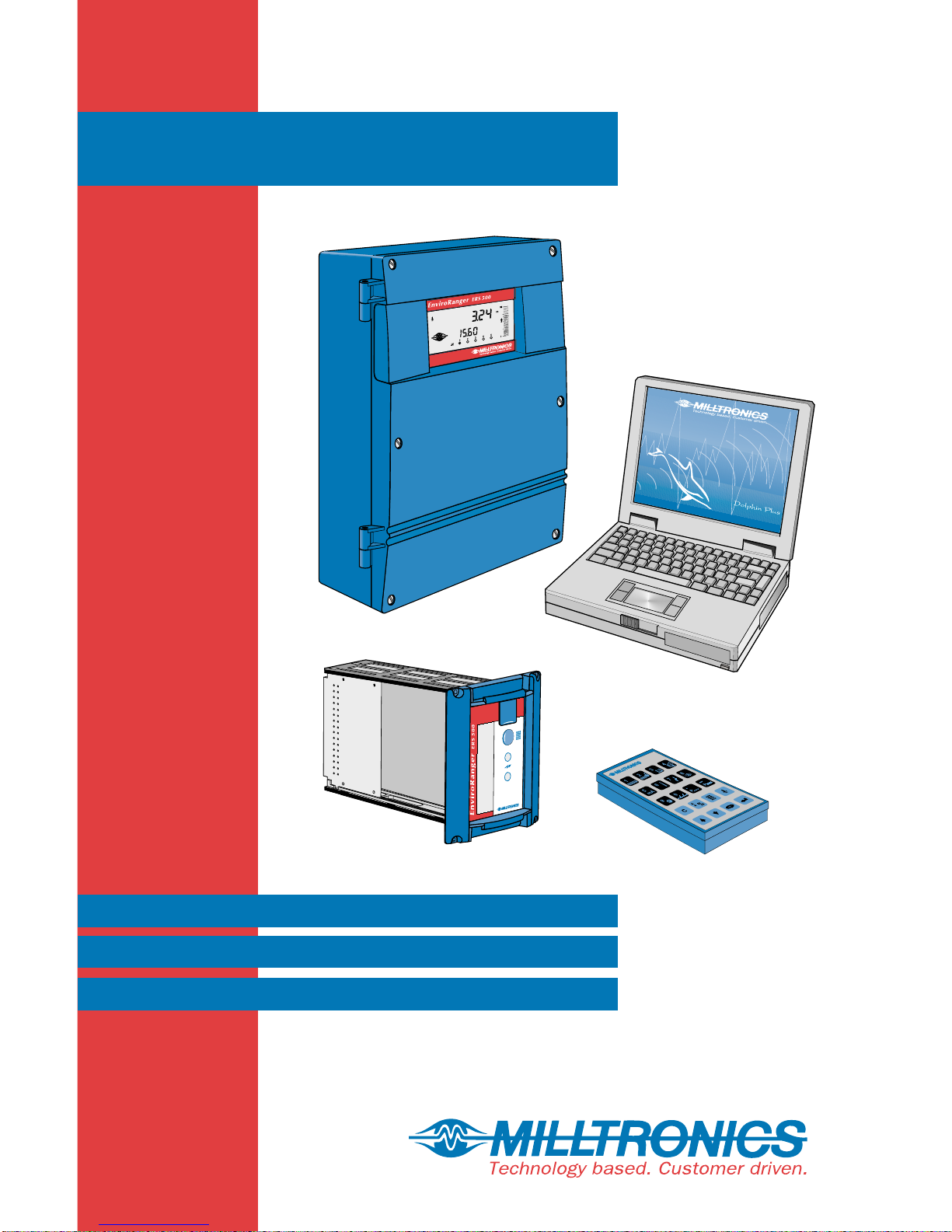
EnviroRanger ERS 500
33455560
Rev 2.0
Programming Reference
PL-556
Nov. 1999
Page 2
t Milltronics, we endeavour
Ultrasonic level
Capacitance
Radar
Po in t level
A
to design equipment that is
simple to use and reliable in its
operation, with the aim of
satisfying our customers' needs.
Milltronics has been designing
and manufacturing electronics
based process measurement
equipment since 1954. Our
fields of expertise include
continuous and point level
measurement, weighing and
feeding systems and motion
sensing.Technologies include
ultrasonic, capacitance and
microwave radar.
Communications
Weigh feeders
Motion sensing
Belt scales
Flowmeters
Acoustic sensing
Milltronics sells and markets
world wide through
subsidiaries, distributors and
representatives. Through
continuous improvement, we
are striving to provide our
customers with first rate sales
information, engineering
assistance and after sales
support.
For more details on our
products and services, please
contact us and we will provide
you with a listing of the offices
or representatives nearest you.
Page 3

Table of Contents
Introduction .......................................................................................... 7
About this Manual............................................................. 7
Using this Manual ............................................................. 8
About the EnviroRanger ...................................................................... 9
Display............................................................................10
Hand Programmer .......................................................... 11
Readings in Run Mode ...................................................12
Programming the EnviroRanger.......................................................15
Starting Program Mode...................................................16
Parameter Indexing.........................................................16
Changing Parameters (Dolphin Plus).............................. 17
Changing Parameters (Hand Programmer) .................... 18
Using Units or Percent (%).............................................. 18
Special Parameters.........................................................19
Parameter Reset............................................................. 19
Security........................................................................... 20
Displays ..........................................................................20
Planning Considerations...................................................................21
Review the Application.................................................... 21
Design the Control Scheme............................................ 21
Install the EnviroRanger.................................................. 21
Program the EnviroRanger.............................................21
Test the Installation.........................................................22
Document the Installation................................................22
Application Examples........................................................................23
Simple Level and Alarms ................................................ 23
Pump Control..................................................................26
Open Channel Monitoring (OCM) ...................................32
Gate Control.................................................................... 44
Rake (Screen) Control....................................................46
Testing the Configuration.................................................................. 49
Simulation....................................................................... 49
I/O Checkout...................................................................51
Application Test ..............................................................52
Programming Documentation .........................................52
Parameter Reference.......................................................................... 55
How to Read the Reference............................................55
Quick Start (P001 to P009) .............................................57
Volume (P050 to P055)................................................... 62
PL-556 EnviroRanger Programming Reference Page 3
Page 4

Display and Reading (P060 to P062)..............................66
Failsafe (P070 to P072) ..................................................69
Relays (P100 to P119).................................................... 72
Pump Setpoint Modifiers (P121 and P122)..................... 88
Independent Relay Failsafe (P129)................................. 90
Advanced Pump Control Modifiers (P130 to P136)......... 91
Pump Energy Cost Reduction (P140 to P145)................95
Overflow / Underflow (P160 to P169)..............................99
Flush Systems (P170 to P173) ..................................... 103
Pump Efficiency (P180 to P186) ................................... 105
mA Input (P250 to P254)............................................... 108
mA Input Trim (P260 to P262) ...................................... 110
Discrete Input Functions (P270 to P275)......................111
Data Logging (P300 to P321)........................................ 115
Record Temperatures (P300 to P303)..........................115
Record Readings (P304 and P305) .............................. 117
Pump Records (P310 to P312) ..................................... 118
Overflow (CSO) Records (P313 to P316).....................119
Flow Records (P320 and P321)....................................120
LCD Totalizer (P322 and P323)....................................121
Profile Records (P330 to P337) .................................... 122
Auto Record “on” and “off” Setpoints (P334 to P337) ... 125
Installation Records (P340 to P342) ............................. 127
Pump Interlock Allocation (P500 to P509).....................128
Pump Fault Status (P510 to P515) ...............................134
Pump Control Source (P520 to P524)........................... 138
OCM (P600 to P621) ....................................................140
Pumped Volume Totalizer (P622 to P623).................... 148
Totalizer (P630 to P645)............................................... 150
Range Calibration (P650 to P654) ................................ 154
Temperature Compensation (P660 to P664) ................157
Rate (P700 to P708) .....................................................159
Measurement Verification (P710 to P713) ....................162
Transducer Scanning (P726 to P728)...........................164
Display (P730 to P739)................................................. 166
SmartLinx Reserved (750 to 769) ................................. 169
Communications (P770 to P782)..................................170
SmartLinx Hardware Testing.........................................175
Echo Processing (P800 to P807).................................. 176
Advanced Echo Processing (P810 to P825)................. 180
Profile Pointer (P817 to P825) ......................................182
Advanced TVT Adjustment (P830 to P835) .................. 185
Advanced Shot Adjustment (P840 to P852).................. 188
Test (P900 to P913)...................................................... 190
Measurement (P920 to P927).......................................193
Master Reset (P999).....................................................196
Page 4 EnviroRanger Programming Reference PL-556
Page 5

Appendix A – Technical Reference.................................................197
Transmit Pulse.............................................................. 197
Echo Processing........................................................... 197
Distance Calculation ..................................................... 198
Sound Velocity.............................................................. 199
Scanning....................................................................... 199
Volume Calculation....................................................... 200
Flow Calculation............................................................ 201
Maximum Process Speed.............................................203
Appendix B – Troubleshooting.......................................................205
Common Problems Chart..............................................205
Noise Problems............................................................. 206
Measurement Difficulties...............................................209
Fixed Reading............................................................... 211
Wrong Reading............................................................. 213
Transducer Ringing.......................................................214
Appendix C – Pump Control............................................................ 215
Pump Control Options................................................... 215
Discrete Inputs.............................................................. 216
Pump Control Algorithms .............................................. 216
Other Pump Controls....................................................221
Appendix D – Discrete inputs.......................................................... 223
Wire the Discrete Input .................................................223
Program the Discrete Input Logic..................................223
Program the Interlock Logic..........................................224
Test the Interlock ..........................................................226
Index.................................................................................................. 227
PL-556 EnviroRanger Programming Reference Page 5
Page 6

Page 6 EnviroRanger Programming Reference PL-556
Page 7

Introduction
The EnviroRanger is intended for advanced water and wastewater
applications. This device can handle virtually all of your pump control and
level monitoring needs – often replacing expensive PLCs and integrating into
a SCADA system for a fraction of the cost of competitive systems.
The EnviroRanger is programmable.
It can be configured for nearly any water or wastewater application and
control up to five pumps, gates, or alarms – and can communicate its status
by way of direct serial connection, modem, or industrial communication
network.
The EnviroRanger is flexible.
It can take discrete input from pumps or other devices and modify its
operation based on that input. It can also time events to maximize efficiency
or minimize cost.
About this Manual
Introduction
This is the Programming Reference manual for the Milltronics EnviroRanger
integrated level monitoring and control system.
The manuals in the EnviroRanger library are:
Manual Uses
Programming Reference
(PL-556)
Installation Guide
(PL-557)
Communications Reference
(PL-558)
• Parameter values
• Parameter uses
• Programming methods
• Outline diagrams
• Wiring diagrams
• Installation requirements
• MODBUS register mapping
• Modem configuration
PL-556 EnviroRanger Programming Reference Page 7
Page 8

Introduction
Using this Manual
Information Section Page
Learn the concepts behind how
the EnviroRanger operates.
Learn how to change parameter
values.
To configure the EnviroRanger
for a particular application.
To test the unit’s programming
before putting it into full
operation..
Find detailed information about
any parameter.
Find detailed information on
how the EnviroRanger uses
ultrasonic technology to detect
levels and convert them to
usable values.
If your EnviroRanger installation
is experiencing problems.
To look up a concept or
keyword.
About the EnviroRanger 9
Programming 15
Application Examples 23
Testing the Configuration 49
Parameter Reference 55
Appendix A – Technical
Reference
Appendix B –
Troubleshooting
Index 227
197
205
Page 8 EnviroRanger Programming Reference PL-556
Page 9

About the EnviroRanger
The EnviroRanger has two modes of operation:
Program Mode
Program mode allows the programmer to change parameter values and alter
the way the unit operates.
Note:
• If the unit has been programmed and is in normal operation then
putting it in program mode will de-energize all control relay outputs.
Therefore it is advisable to bypass the EnviroRanger while
programming the unit to avoid overflows.
• After a programming alteration, do not use the EnviroRanger to
operate alarms or controls until system programming and performance
is verified.
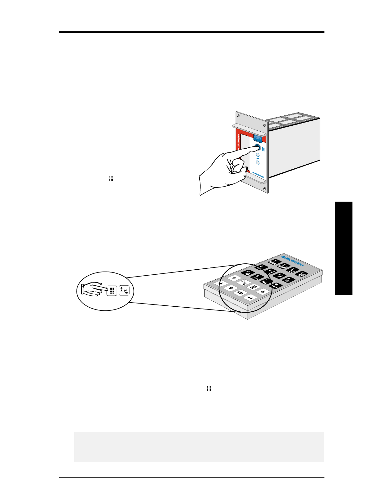
To enter Program mode from Run mode:
About the EnviroRanger
1. Press the program button on the front of the device (Rack or Panel only)
2. Look for the program icon on the display (
3. Press
If the EnviroRanger is idle in Program mode for more than 5 minutes, then
Run mode is automatically entered.
For information on the individual programming parameters see the chapters
Application Examples on page 23 or Parameter Reference on page 55.
and then .
) (Rack or Panel only)
Run Mode
Run mode detects material level and provides control functions. The
EnviroRanger automatically starts up in the Run mode when power is
applied.
To enter Run mode from Program mode, press
“----“ is displayed briefly while the measurement reading is calculated and
verified. Reading level and other data is displayed and any relays are
operated based on the unit’s programming.
.
While the unit is in Run mode you can view system status. This information
is shown on the LCD on the front of the unit or can be accessed remotely
using communications software.
PL-556 EnviroRanger Programming Reference Page 9
Page 10
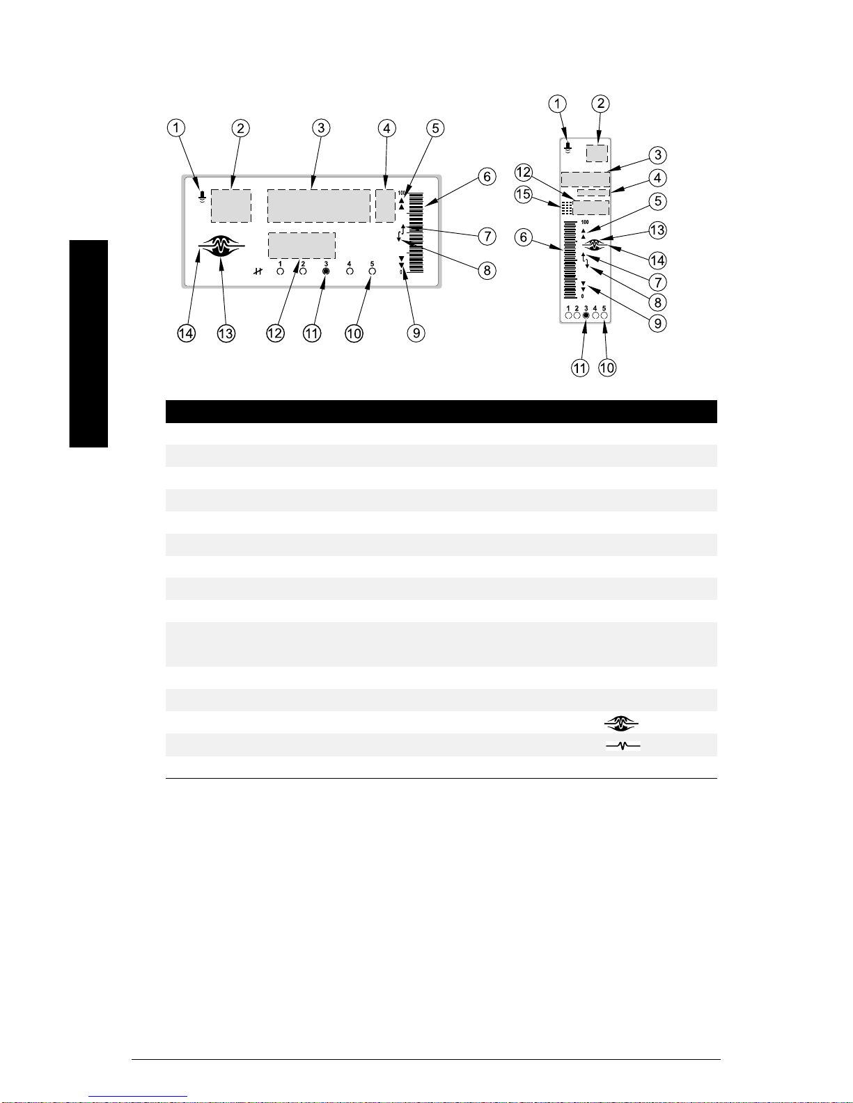
Display
About the EnviroRanger
Wall Mount Rack or Panel Mount
Program Mode Run Mode
1 index type index type
2 index index
3 parameter value primary reading
4 units units
5 auxiliary function hi and hi hi alarm
6 n/a level display
7 scroll access tag filling display
8 scroll access tag emptying display
9 n/a loandloloalarm
relay # programmed
10
flashing = unavailable
11 relay # activated relay # activated
12 parameter number auxiliary reading
13 n/a
14 n/a failsafe operation:
15 program mode programming enabled
relay # programmed
flashing = unavailable
normal operation:
Page 10 EnviroRanger Programming Reference PL-556
Page 11
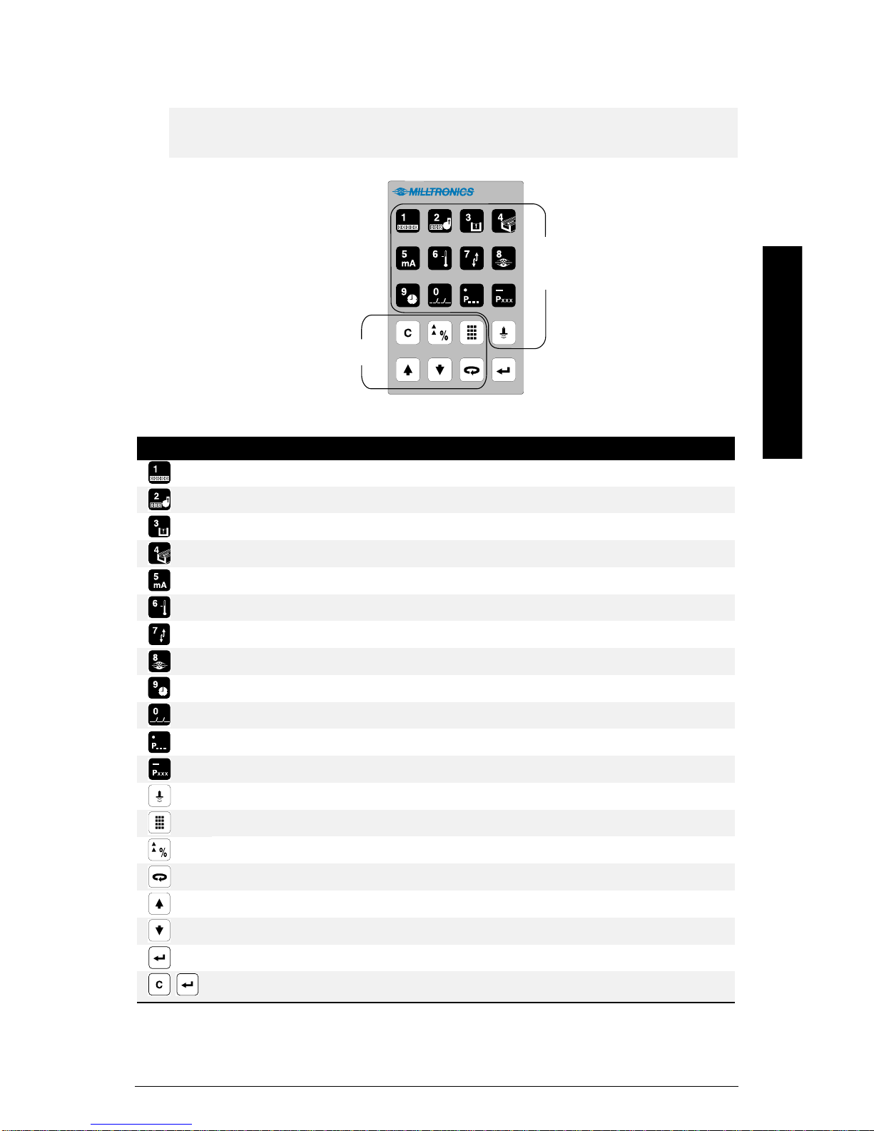
Hand Programmer
y
Note:
The hand programmer is ordered separately from Milltronics.
Function
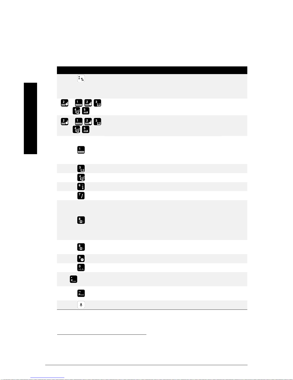
Key Programming Mode Run Mode
1 8-digit Totalizer (toggle)
2 Pump Running Time
3 Head
4 Flow based on Head
5
6 Temperature
7 Rate of Change
Numeric
and
Auxiliar
About the EnviroRanger
8 Failsafe Time Left
9Time
0 Date
Decimal Point (TVT left) Parameter Value
Negative Value (TVT right) Material Level (P731)
Fire Transducer Distance
Run Mode Program Mode (Key 1)
Units or % Units or % (Program Mode (Key 2))
Next Display Field Pause Display Toggle
Increase Value Next Index
Decrease Value Previous Index
Enter Value
,
Clear to Preset
PL-556 EnviroRanger Programming Reference Page 11
Page 12
Readings in Run Mode
When the EnviroRanger is in run mode the values displayed can be changed
by using keys on the hand programmer.
All readings are shown in the Auxiliary field except for the totalizer and P920.
PressthisKey Function P#
Toggle Readings between percent and units P920
Level Space or Distance
0 to 100% 100 to 0%
+
Accumulated pump running hours2for
numbered pump
1
P310
About the EnviroRanger
+
Hold number key for five seconds to display
the number of accumulated pump starts2for
P311
numbered pump
8-digit totalizer, uses index and reading
areas, press again to toggle, P737 sets
default
P322,
P323,
P920
Used for OCM and Pumped Volume.
Head measurement
Instantaneous flow based on head (OCM)
Temperature
Rate of level change
P926
P925
P664
P707
Failsafe Time Left (in %). When the Reading
is updated, this value (Auxiliary Reading)
resets to 100 and begins to decrease until
the next valid measurement is made. If the
Failsafe Time Left reaches 0, “LOE” flashes
in the Reading display.
Hold for four seconds to show echo
P805
confidence
Time (hh:mm)
P009
+ ###
1
Distances less than 0.3m (12”) from the transducer face cannot be reliably measured
so a 0% rea ding cannot be achieved during “distance” operation.
2
If the associated relay is programmed for pump control.
Page 12 EnviroRanger Programming Reference PL-556
Date (dd:mm or mm:dd as P736)
Display the value of the entered parameter
which is global or indexed by transducer
Auxiliary reading, displays parameter
specified in P731
Distance
P008
typed
number
P731
P923
Page 13

Scrolling Display
During “differential” or “average” Operation (P001 = 4 or 5), the display
scrolls sequentially through Point Numbers 1, 2, and 3. Point Number 3
represents the difference between or average of Point Numbers 1 and 2.
See Display (P730 to P739) on page 166 for more information.
About the EnviroRanger
PL-556 EnviroRanger Programming Reference Page 13
Page 14

About the EnviroRanger
Page 14 EnviroRanger Programming Reference PL-556
Page 15
Programming the EnviroRanger
To meet the needs of any given application the EnviroRanger must be
correctly programmed. The EnviroRanger is programmed by changing
parameter values. The available parameters are described in detail in the
Parameter Reference on page 55 and sample applications are given in
Application Examples on page 23.
Rack or Panel Mount
To enter program mode on a rack
or panel mount unit:
Press the program button on the
front of the unit (shown at right)
This icon (
canbeplacedinprogrammode.
) appears when the unit
Wall Mount
The wall mount version has no program button, it is always ready for
program mode.
Aim the hand programmer and press the program keys on the hand
programmer (shown above).
Programming
The program button allows multiple units to be installed close together and
still be programmed one at a time.
Program mode is confirmed by the icon (
disable programming, press again. Run mode is confirmed by absence of
the icon in the display. Disable all nearby units to avoid inadvertent
programming when using the infrared handheld programmer.
Note:
Unless otherwise noted, each valid key press should produce a change in
the LCD, look for this when programming the unit.
PL-556 EnviroRanger Programming Reference Page 15
) appearing in the display. To
Page 16

Starting Program Mode
Entering program mode has the following effects:
• all operating data is retained in memory
• alarm relay status is held at last known values
• control relays are de-energized (unless affected by parameter alteration or
is pressed)
• discrete inputs are detected but not acted on
The Run mode is automatically re-entered if the EnviroRanger is left
unattended in the program mode for an extended period (approximately 5
minutes).
Parameter Indexing
Parameters are indexed if they can apply to more
than one input or output. The index value defines to
which input or output the particular parameter value
relates. Indexed parameters contain a value for
each index, even if that index is not used.
Note:
To set all indexed values for a given parameter to the same value use
index “0”.
Programming
For example, to change the Relay Control Function (P111) for relay three
you must ensure that “03” is displayed in the index field before you change
the parameter value.
In this manual parameter index values are shown in brackets after the
parameter number. For example P111[3] refers to parameter 111 index
value 3.
Note:
Transducer parameters are indexed only if Operation (P001) is set to
“Difference” (value=4) or “Average” (value=5). An indexed transducer is
commonly referred to as a Point (short for measurement point). The term
Point Number refers to indexed transducers.
index
field
rack or panel display shown
Page 16 EnviroRanger Programming Reference PL-556
Page 17
To access the index of a particular parameter:
w
r
r
• Press
once
• Enter the parameter number
• Press
twice
• Press the number of the required index, or
• Press
or to scroll through the available values
Note:
When dealing with indexed parameters it is critical to ensure that you set
the values accurately. Take extra time to ensure that the correct index
value is being changed for each parameter value.
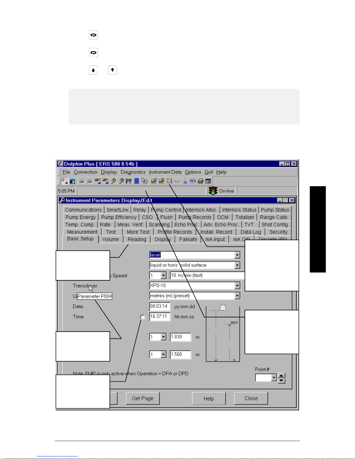
Changing Parameters (Dolphin Plus)
Tabs sho
groups of
parameters
Parameters have
roll-overs which
show numbe
Programming
The attached
device can be
programmed,
debugged, and
monitored from
Dolphin Plus
The status bar
informs you of
program actions
and data transfer
status
Parameters can
be tracked while
the EnviroRange
is running
PL-556 EnviroRanger Programming Reference Page 17
Page 18

Dolphin Plus is the primary method of changing EnviroRanger parameters.
Most examples in this manual use the icons from the hand programmer but
nearly all functions are also available through Dolphin Plus.
The Dolphin Plus software is available separately from Milltronics.
Changing Parameters (Hand Programmer)
1. From Run mode, press and then to put the unit into Program mode.
Note:
If Parameter Value alteration is not permitted, access the Lock parameter
(P000) and enter the security code, (see Programming Security).
2. Press to select the Parameter Number field (see page 10)
3. Type the Parameter Number (e.g. 110)
When you type the third digit the value for that parameter is shown
For lower numbered parameters, such as 007, you can type the number “7”
and then press
4. Type the new value
5. Press
Programming
The EnviroRanger interprets the value and either accepts it, or replaces it
with a valid value. See the Parameter Reference for descriptions of values.
The “?” icon indicates that the EnviroRanger has accepted the value but that
it conflicts with other values entered. Double-check your programming.
By default the scroll keys (
and any that have been changed. Use P733 (G) Scroll Access on page 167
to allow all parameters to be scroll-accessed.
Using Units or Percent (%)
Many parameters can be viewed in either measurement units (P005) or
percent. View the parameter and then press the
units and percent. The LCD shows the current measurement type, either
units (m, mm, ft, etc.) or percent (%).
to show that parameter.
to enter the new value
or ) only show the Quick Start parameters
key to toggle between
Page 18 EnviroRanger Programming Reference PL-556
Page 19

Special Parameters
View Only
Some Parameter Values are for display purposes only and cannot be
altered. These are referred to as view only parameters.
In the Parameter Reference section of this instruction manual, view only
parameters are identified by a “(V)” beside the Parameter Number.
Global
Some parameter values must be common for all inputs and outputs on the
EnviroRanger. These are referred to as global parameters.
When a global parameter is accessed, the index display automatically
disappears. When a non-global parameter is accessed, the index previously
selected for that parameter is displayed.
In the Parameter Reference section of this manual, Global parameters are
identified by a “(G)” beside the Parameter Number.
Indexed
Some parameter values relate to indexed items. Examples of this are
parameters which are different for each:
• Relay, shown with an “(IR)”
• Transducer, shown with an “(IT)”
• Discrete Input, shown with an “(IDI)”
For full descriptions of parameters and how they are indexed, see How to
Read the Reference on page 55.
Parameter Reset
To set any parameter back to the factory default:
• Display the appropriate parameter number
• Display the appropriate index value (if required)
• Press
• Press
Programming
To reset all parameters to preset values, see Master Reset (P999).
Perform a Master Reset (P999) to reset all parameters to “original” values
before initial system installation, following a software upgrade, or whenever
complete reprogramming is required. Use Dolphin Plus to store and retrieve
parameter groups.
PL-556 EnviroRanger Programming Reference Page 19
Page 20

Security
All operator programming is retained in non-volatile memory, immune to power
interruptions. When programming is complete, the programmer may be locked
away to prevent inadvertent programming alteration. As well, the Lock (P000)
parameter may be used.
Displays
The following displays are shown when the EnviroRanger cannot display a
number.
Display Meaning
parameter has not been set
all values not same when viewing index 0
parameter entered does not exist for this device
Programming
Page 20 EnviroRanger Programming Reference PL-556
Page 21

Planning Considerations
Review the Application
When reviewing the application into which the EnviroRanger will be installed,
note the:
• Pump control system inputs and outputs
• Dimensions of the wet well or reservoir (especially if pumped volume will be
used)
• Maximum measurement distance required (will determine transducer
requirement)
• Communication type required (modem, industrial communication network)
Design the Control Scheme
Choose the most appropriate pump control strategy from those available.
See Appendix C – Pump Control on page 215 for a description of the
EnviroRanger pump control strategies and options.
Map the Control Scheme to EnviroRanger
Once the control scheme is designed, map its requirements to the
EnviroRanger’s parameters. Be aware of the EnviroRanger’s abilities:
• Number of relay outputs (5)
• Number of discrete inputs (8)
• Number of mA inputs (1)
Install the EnviroRanger
Mount and wire the EnviroRanger as detailed in the EnviroRanger
Installation Guide (PL-557).
Program the EnviroRanger
Use the Application Examples (page 23) and Parameter Reference (page
55) to determine the best method of programming the EnviroRanger to
satisfy the control scheme.
Planning
Use either Dolphin Plus or a hand programmer to set the parameter values
to those required.
PL-556 EnviroRanger Programming Reference Page 21
Page 22

Test the Installation
Test the inputs and outputs as shown in Testing the Configuration on page
49.
Document the Installation
Use Dolphin Plus to record your parameter values for later reference.
Planning
Page 22 EnviroRanger Programming Reference PL-556
Page 23
Application Examples
Note:
When the unit is first turned on it will give distance (P001=3) in meters
from the transducer face to the material surface. If the wet well or reservoir
is empty then this reading is the empty distance (P006) from the
transducer face to the reservoir bottom. P006 is preset to 5.0m (16.4’), so
reservoirs deeper than that will read LOE until P006 is updated.
Output Limitations
The standard EnviroRanger comes with 5 relay outputs. Each relay is
programmed using P111 (IR) Relay Control Function (see page 74) from a
large number of options. Use these application examples as a guideline for
the relay programming.
Simple Level and Alarms
See Parameter Reference on page 55 for complete details on specific
parameter values.
P006
hi hi
hi
P007
lo
lo lo
Set the Common Parameters
Prerequisite: You must know the details of your application and substitute
the values for the sample values provided. If you are bench testing the unit
then set your test values to be the same as the sample values.
Parameter Index Value Description
P001 G 1 Operation = level
P002 G 1 Material = liquid
P003 G 2 Maximum Process Speed = medium
P004 G 102 Transducer = XPS-10
P005 G 1 Units = meters
P006 G 1.8 Empty = 1.8m
P007 G 1.4 Span = 1.4m
Applications Examples
PL-556 EnviroRanger Programming Reference Page 23
Page 24

Setting a High High Alarm
Parameter
P111 1 1
P112 1 1.2m
P113 1 1.15m
Relay
Index
Value Description
These settings trip the alarm when the
level rises above 1.2m and reset the
alarm when the level falls below 1.15m.
Setting a Low Alarm
Parameter
P111 3 1
P111 Aux. L
P112 3 0.3
P113 3 0.4
To select a Level Alarm Designation (L,LL,H,HH or blank) do the following:
1. Press
2. Press
3. Press
to display the Auxiliary Function symbol,
or as required to scroll to the alarm designation,
to enter the value.
Relay
Index
Value Description
These settings trip the alarm when the
level falls below 0.3m and reset the
alarm when the level rises above 0.4m.
The low alarm (▼) icon is displayed on
the LCD when the alarm is tripped.
Setting a Loss of Echo (LOE) Alarm
Parameter
P111 5 6
P070 G 0.5
Relay
Index
Value Description
These settings trip the alarm when 0.5
minutes (30 seconds) pass without a
valid echo being detected.
Setting an Out of Bounds Alarm
Parameter
P111 5 3
P112 5 1.3
P113 5 0.3
P116 5 0.05
Relay
Index
Value Description
These settings do the following:
trips alarm resets alarm
above 1.35m below 1.25m
below 0.25m above 0.35m
Application Examples
Page 24 EnviroRanger Programming Reference PL-556
Page 25

Setting a Filling Rate Alarm
Parameter
P111 5 4
P112 5 1m
P113 5 0.9m
Relay
Index
Value Description
These settings trip the alarm when the
reservoir is filling faster than 1m per
minute and reset it at 0.9m per minute.
Setting an Emptying Rate Alarm
Parameter
P111 5 4
P112 5 -10%
P113 5 -5%
Relay
Index
Value Description
These settings trip the alarm when the
reservoir is emptying faster than 10% of
span per minute and reset the alarm
when emptying falls to 5%..
PL-556 EnviroRanger Programming Reference Page 25
Applications Examples
Page 26
Pump Control
See Parameters section for complete details on specific parameter values.
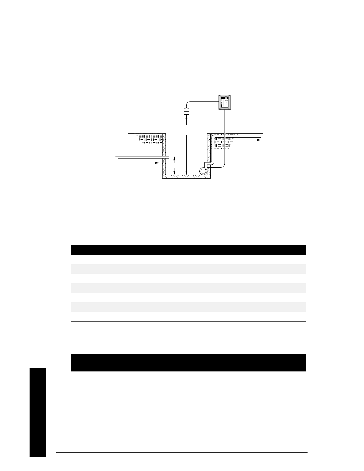
Setting a Pump Down (Wet Well) Group
Sets a group of three pumps to pump down a wet well.
EnviroRanger with
advanced pump
control algorithms
P006
outflow
inflow
P007
Set the Common Parameters
Prerequisite: You must know the details of your application and substitute
the values for the sample values provided. If you are bench testing the unit
then set your test values to be the same as the sample values.
Parameter Index Value Description
P001 G 1 Operation = level
P002 G 1 Material = liquid
P003 G 2 Maximum Process Speed = medium
P004 G 102 Transducer = XPS-10
P005 G 1 Units = meters
P006 G 1.8 Empty = 1.8m
P007 G 1.4 Span = 1.4m
Set the Pump Relays to “Alternate duty assist”
Parameter
P111 1 52
P111 2 52
P111 3 52
Application Examples
Page 26 EnviroRanger Programming Reference PL-556
Relay
Index
Value Description
Sets the pump relays (index 1, 2, and 3)
to “alternate duty assist”.
Page 27

Set the “On” Setpoints
Parameter
P112 1 1.0m
P112 2 1.1m
P112 3 1.2m
Relay
Index
Value Description
Sets the three setpoints for the pump
relays. The first cycle will use these
setpoints. Subsequent cycles rotate the
setpoints among the pumps.
Set the “Off” Setpoints
Parameter
P113 0 0.5m
Relay
Index
Value Description
By using index 0 all five relays are set
at the same time, including any alarm
relays. Use index 0 with caution.
Optional: Starting Pumps by Rate of Level Change
Parameter
P112 1 1.35
P112 2 1.35
P112 3 1.35
P113 1 0.5m
Relay
Index
Value Description
Starting pumps by rate allows all
setpoints to be set higher to save money
by pumping from the highest safe level of
the wet well.
P113 2 0.5m
P113 3 0.5m
P121 1 1
P121 2 1
P121 3 1
P132 G 20.0
Notice that all indexed relays for both
P112andP113aresettothesame
levels.
The pumps will start on 20 second
intervals until the rate set in P703 is met.
Optional: Rotating Pumps by Service Ratio
Prerequisite: the pump relays must be set to a “service ratio” value (P111 =
54 or 55).
Parameter
P122 1 1
P122 2 2
P122 3 1
Relay
Index
Value Description
These values will start pump 2 50% of
the time and pumps 1 and 3 25% of the
time each.
Applications Examples
PL-556 EnviroRanger Programming Reference Page 27
Page 28

Optional: Totalizing Pumped Volume
Prerequisite: the volume of the wet well or reservoir must be known.
Parameter Index Value Description
P001 G 7 Operation = pumped volume
P002 G 1
P003 G 2
P004 G 102
P005 G 1
P006 G 1.8
P007 G 1.4
P050 G 1 Tank volume is “flat-bottom”
P051 G 17.6 Max volume is 17.6 m3or 17,600 liters
P111 1 52
P111 2 52
P111 3 52
P112 1 1.0
P112 2 1.2
P112 3 1.4
P113 0 0.2 Sets the “off” setpoints for all relays.
These parameters are “as above.”
Sets relays 1, 2, and 3 as a pump group
using Alternate Duty Assist control.
Sets the “on” setpoints for the pump
group.
Run Mode
• Press
• Press
• Press
to enter Run mode.
to display the pumped volume on the totalizer.
to display the current level in the auxiliary reading area.
Other Optional Functions
Function Page Description
Independent Failsafe 90 Overrides default per relay
Pump Run-on 91 Pumps past “off” setpoint
Pump Start Delay 92 Staggers pump starts
Power Resumption Delay 92 Delays first pump start
Pump Exercising 93 Pumps based on time
Wall Cling Reduction 93 Randomizes setpoints
Pump Group 94 Separates pump groups
Pump Energy Saving 95 Pumps during low cost periods
Overflow Handling 99 Reaction to overflow events
Flush Systems 103 Controls a flush device
Pump Efficiency Testing 105 Removes poor performing pumps
Application Examples
Page 28 EnviroRanger Programming Reference PL-556
Page 29
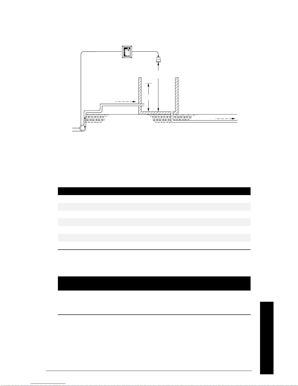
Setting a Pump Up (Reservoir) Group
Sets a group of three pumps to pump up a reservoir.
EnviroRanger with
advanced pump
control algorithms
P006
inflow
P007
outflow
Set the Common Parameters
Prerequisite: You must know the details of your application and substitute
the values for the sample values provided. If you are bench testing the unit
then set your test values to be the same as the sample values.
Parameter Index Value Description
P001 G 1 Operation = level
P002 G 1 Material = liquid
P003 G 2 Maximum Process Speed = medium
P004 G 102 Transducer = XPS-10
P005 G 1 Units = meters
P006 G 1.8 Empty = 1.8m
P007 G 1.4 Span = 1.4m
Set the Pump Relays to “Alternate Duty assist”
Parameter
P111 1 52
P111 2 52
P111 3 52
PL-556 EnviroRanger Programming Reference Page 29
Relay
Index
Value Description
Sets the pump relays (index 1, 2, and
3) to “alternate duty assist”.
Applications Examples
Page 30

Set the Relay “On” Setpoints
Parameter
P112 1 0.4m
P112 2 0.3m
P112 3 0.2m
Relay
Index
Value Description
Set the Relay “Off” Setpoints
Parameter
P113 0 1.3m
Note:
Optional parameters found on page 28.
Relay
Index
Value Description
Sets the three setpoints for the pump
relays. The first cycle will use these
setpoints. Subsequent cycles rotate
the setpoints among the pumps.
By using index 0 all relays are set to
the same value.
Application Examples
Page 30 EnviroRanger Programming Reference PL-556
Page 31

Connecting a Pump Control Interlock
P006
EnviroRanger with
advanced pump control
algorithms using pump
interlocks
outflow
discrete input
relay output
Parameter
inflow
Relay
Index
P007
Value Description
P111 1 52
P111 2 52
Sets the pump relays (index 1, 2, and
3) to “alternate duty assist”.
P111 3 52
P505 1 3
P505 2 4
P505 3 5
Sets discrete inputs 3, 4, and 5 as the
inputs for the pumps attached to relays
1, 2, and 3 respectively.
These values will ensure that any pump reporting a failure is removed from
the pumping rotation. For more information on pump interlocks and discrete
inputs see:
• Discrete Input Functions (P270 to P275) on page 110
• Pump Interlock Allocation (P500 to P509) on page 128
• Appendix C – Pump Control on page 215
PL-556 EnviroRanger Programming Reference Page 31
Applications Examples
Page 32

Open Channel Monitoring (OCM)
See Parameters section for complete details on specific parameter values.
There are three ways of defining an OCM installation depending on your
Primary Measuring Device (PMD). See the listed examples for required
parameters.
• Dimensional
is provided for some common weir and flume typ es. For these PMDs the
dimensions (P602) are entered directly.
• Exponential
is provided for most other weir and flume types. For these PMDs the
exponent provided by the manufacturer is entered. Flow is calculated using
the exponent (P601) and the maximum values (P603 and P604).
• Universal
is provided to accommodate any installation not covered by the first two
types. For all other PMDs the head-to-flow curve can be plotted and
approximated based on known breakpoints, usually supplied by the PMD
manufacturer.
Dimensional (P600=2,3,6,7)
• BS-3680 / ISO 1438/1 Thin plate V notch weir on page 35
• BS-3680 / ISO 4359 Rectangular Flume on page 36
• Palmer Bowlus Flume on page 37
• H Flume on page 38
Exponential (P600=1)
• Standard Weirs on page 39
• Parshall Flume on page 40
• Leopold Lagco on page 41
• Cut Throat Flume on page 42
Universal (P600=4,5)
• Typical Flow Characterization on page 42
• Example Flumes on page 43
• Example Weirs on page 43
Application Examples
Page 32 EnviroRanger Programming Reference PL-556
Page 33

Set the Common Parameters
These “Quick Start” parameters are required for all installations.
Dimension examples
on next page.
Parameter Index Value Description
P001 G 6 Operation = OCM
P002 G 1 Material = liquid
P003 G 2 Maximum Process Speed = medium
P004 G 102 Transducer = XPS-10
P005 G 1 Units = meters
P006 G 1.8 Empty = 1.8m
P007 G 1.0 Span = 1.4m
P801 G 0.8 Range Extension to avoid “LOE”
PL-556 EnviroRanger Programming Reference Page 33
Applications Examples
Page 34

Setting Zero Head
Many PMDs trap a pool of liquid when there is no flow. There are two
methods of accounting for this trapped liquid:
1. Use P605 Zero Head to raise the start of Span (P007) above the Empty
distance (P006). See P605 (G) Zero Head on page 143.
P006
P007
P605
P603
2. Use P801 Range Extension to ignore readings below the artificially-short
Empty distance (P006). See P801 (G) Range Extension on page 176.
P006
P603
P007
P801
The examples on the following pages show both methods.
Application Examples
Page 34 EnviroRanger Programming Reference PL-556
Page 35

Setting Totalized Volume
To display the totalized volume on the LCD use the following parameters:
Parameter Index Value Description
P737 G 2
Show the eight digit totalizer in the
primary display
Direct Support
BS-3680 / ISO 1438/1 Thin plate V notch weir
transducer
4to5xh
max
(h
= P007)
max
notch angle
P602
P006
P603
P007
P801
Parameter Index Value
P600 G 7 – ISO 1438/1 V Notch Weir
P602 1 Notch angle
(view only)
P603 G Maximum Head (preset to P007)
P801 G Range Extension
P608 G Flowrate Units
PL-556 EnviroRanger Programming Reference Page 35
Applications Examples
2 Discharge coefficient (Ce)
Page 36

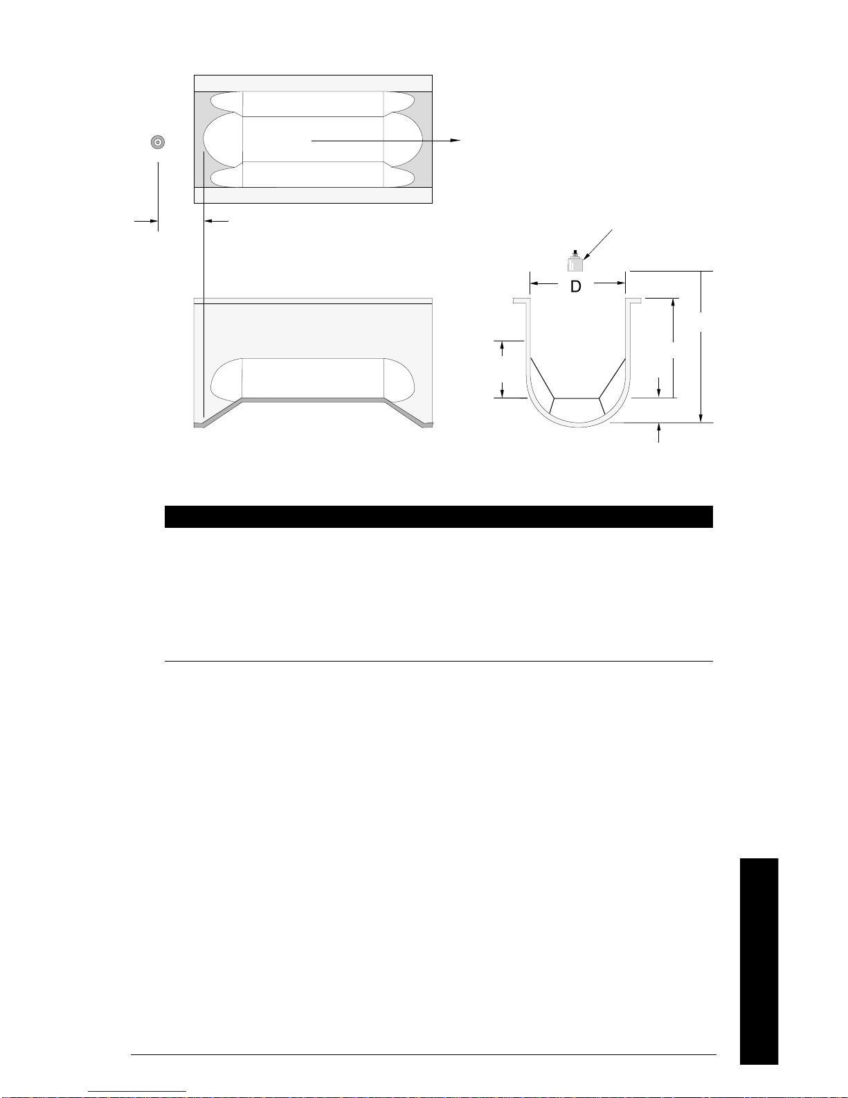
BS-3680 / ISO 4359 Rectangular Flume
h
3to4xh
P006
max(hmax
= P007)
L
flow
transducer
h
P605 (p)
Parameter Index Value
P600 G 6 – ISO 4359 Rectangular Flume
P602 1 Approach width (B)
2 Throat width (b)
3 Hump Height (p)
4 Throat length (L)
(view only) 5 Velocity coefficient (Cv)
(view only) 6 Discharge coefficient (Cd)
(view only) 7 Cross sectional area
P605 G Zero Head
P608 G Flowrate Units
flow (P608)
Application Examples
Page 36 EnviroRanger Programming Reference PL-556
Page 37
Palmer Bowlus Flume
Flow
D/2, point of
measurement
Side view
Plan view
P603
Front view
Parameter Index Value
P600 G 2 – Palmer Bowlus Flume
P602 1 Flume width (D)
P603 G Maximum Head (preset = P007)
P604 G Maximum Flow
P605 G Zero Head
P606 G Time Units
transducer
P006
P007
P605
• Sizedbypipediameter,D
• Flume relief is trapezoidal
• Designed to install directly into pipelines and manholes
• Head is referenced to bottom of the throat, not bottom of the pipe
• For rated flows under free flow conditions, the head is measured at a
distance of D/2 upstream from the beginning of the converging section
PL-556 EnviroRanger Programming Reference Page 37
Applications Examples
Page 38

HFlume
r
Parameter Index Value
transduce
point of measurement
plan view
P006
P007
front view side view
P600 G 3–HFlume
P602 1 Flume height (D)
P603 G Maximum Head (preset = P007)
P604 G Maximum Flow
P606 G Time Units
• Sized by maximum depth of flume, D
• Approach is preferably rectangular, matching width and depth for distance 3
to 5 times the depth of the flume
• May be installed in channels under partial submergence (ratio of
downstream level to head). Typical errors are:
• 1% @ 30% submergence
• 3% @ 50% submergence
• For rated flows under free flow conditions, the head is measured at a point
downstream from the flume entrance
Flume Size
(D in feet)
Point of Measurement
cm inches
0.5 5 1¾
0.75 7 2¾
1.0 9 3¾
1.5 14 5½
2.0 18 7¼
2.5 23 9
3.0 28 10¾
4.5 41 16¼
• H flumes come with a flat or sloping floor. The same flow table can be used
as error is less than 1%.
Application Examples
Page 38 EnviroRanger Programming Reference PL-556
Page 39

PMDs with Exponential Flow to Head Function
For Primary Measuring Devices (PMDs) that measure flow by an exponential
equation use these parameters. Ensure that you use the correct exponent
for your PMD, the values below are samples only.
Standard Weirs
weir profile
Applicable Weir Profiles
transducer
V-notch or
triangular
suppressed
rectangular
cipolleti or
trapezoidal
sutro or
proportional
Parameter Index Value
P600 G 1 – Exponential Function
P601 G
Weir Type Value
†
V-notch 2.50
Suppressed rectangular 1.50
Cipolletti or trapezoidal 1.50
Sutro or proportional 1.00
P603 G Maximum Head
P604 G Maximum F low
P606 G Time Units
P801 G Range Extension
† These values are samples only. Consult your weir manufacturer’s
documentation for the correct flow exponent.
Applications Examples
PL-556 EnviroRanger Programming Reference Page 39
Page 40

Non-Applicable Weir Profiles
2
contracted
compound Poebing
approximate
rectangular
Flows through these weirs can be measured using the universal flow
calculation P600 = 4 or 5. See Universal Calculation Support on page 42.
Parshall Flume
C
C = converging dimension
/3C
Plan View
transducer
exponential
• sized by throat width
• set on solid foundation
• For rated flows under free flow conditions the head is measured at
Application Examples
P006
Front View Side View
2
/3the
length of the converging section from the beginning of the throat section.
Parameter Index Value
P600 G 1 – Parshall Flume
P601 G 1.22 – 1.607 (consult your flume documentation)
P603 G Maximum Head
P604 G Maximum Flow (Q)
P606 G Time Units
Page 40 EnviroRanger Programming Reference PL-556
Page 41

Leopold Lagco Flume
converging diverging
throat
plan view
transducer
point of measurement
P007
P603
0
side view
Head
front view
P605
Parameter Index Value
P600 G 1 – Leopold Lagco Flume
P601 G 1.55
P603 G Maximum Head (preset P007)
P604 G Maximum Flow
P605 G Zero Head
P606 G Time Units
• Designed to be installed directly into pipelines and manholes
• Leopold Lagco may be classed as a rectangular Palmer-Bowlus flume
• Sized by pipe (sewer) diameter
• For rated flows under free flow conditions the head is measured at a point
upstream referenced to the beginning of the converging section. Refer to the
following table:
P006
diameter in inches)
4-12 2.5 1
15 3.2 1¼
18 4.4 1¾
21 5.1 2
24 6.4 2½
30 7.6 3
42 8.9 3½
48 10.2 4
54 11.4 4½
60 12.7 5
66 14.0 5½
72 15.2 6
PL-556 EnviroRanger Programming Reference Page 41
Point of MeasurementFlume Size (pipe
cm inches
Applications Examples
Page 42

CutThroatFlume
Plan View
• Similar to Parshall flume except that the floor is flat bottomed and throat has
no virtual length.
• Refer to manufacturer’s specifications for flow equation and point of head
measurement.
Parameter Index Value
P600 G 1 – Cut Throat Flume
P601 G 1.55
P603 G Maximum Head (preset P007)
P604 G Maximum Flow
P606 G Time Units
Universal Calculation Support
When the primary measuring device (PMD) doesn’t fit one of the standard
types it can be programmed using a universal characterization. When
Universal is selected as the PMD type (P600) then both P610 and P611
must be entered to define the flow.
Two curve types are supported:
• P600 = 4 – linear (piecewise linear)
• P600 = 5 – curved (cubic spline)
Both are shown in the following chart:
Typical Flow Characterization
Maximums (P603, P604)
linear
Flow (P611)
Application Examples
Page 42 EnviroRanger Programming Reference PL-556
curved
Head (P610)
Page 43

Characterization is achieved by entering the head (P610) and corresponding
flow (P611), either from empirical measurement or from the manufacturer's
specification. The more breakpoints that are defined, the more accurate will
be the flow measurement. Breakpoints should be concentrated in areas
exhibiting the higher degrees of non linear flow. A maximum of 32
breakpoints can be defined. The curve’s end point is always specified by the
parameters Maximum Head (P603) and Maximum Flow (P604) for a
maximum total of 33 breakpoints.
Use as many breakpoints as required by the complexity of your PMD.
See Flow Calculation on page 201 for more information.
Example Flumes
These example flumes would both require a universal calculation.
Trapezoidal
Dual Range (nested) Parshall
Example Weirs
These weirs could require universal calculation.
contracted
rectangular
For further information regarding universal flow calculations, see Flow
Calculation on page 201.
compound Poebing
Applications Examples
approximate
exponential
PL-556 EnviroRanger Programming Reference Page 43
Page 44

Gate Control
See Parameters section for complete details on specific parameter values.
This technique can also be applied to some types of valves.
Setting a Gate (Penstock) Control
transducer
overflow
gate
flow direction
Set the Common Parameters
Prerequisite: You must know the details of your application and substitute
the values for the sample values provided. If you are bench testing the unit
then set your test values to be the same as the sample values.
12
relays
Parameter Index Value Description
P001 G 1 Operation = Level
P002 G 1 Material = liquid
P003 G 2 Maximum Process Speed = medium
P004 G 102 Transducer = XPS-10
P005 G 1 Units = meters
P006 G 1.8 Empty = 1.8m
P007 G 1.4 Span = 1.4m
Application Examples
Page 44 EnviroRanger Programming Reference PL-556
Page 45

Set Relay 1 (Open Gate)
Relay 1 is wired to the “open” connections on the gate control. When relay 1
is energized the gate moves up.
Parameter Index Value Description
P111 1 63
P112 1 45%
P113 1 ---P114 1 0.1
P115 1 0.02
Sets relay 1 to energize (open gate)
when the level is below 45% of the span
(0.63m). The gate will open for 0.1
minute (6 seconds) and this cycle will
happen once per 0.02 hours (1 minute,
12 seconds) until the level is above 45%
Set Relay 2 (Close Gate)
Relay 2 is wired to the “close” connections on the gate control. When relay 2
is energized the gate moves down.
Parameter Index Value Description
P111 2 63
P112 2 55%
P113 2 ----
Sets relay 2 to energize (close gate)
when the level is above 55% of the span
(0.77m). The timing (P114, P115) of
relay 2 is set from the relay 1 setpoints.
Note:
Care must be taken to adjust P114 and P115 for proper proportional
integral (PI) control without overshoot or cycling. P114 is equivalent to
proportional band (P). P115 is equivalent to reset (I).
The transducer can also be placed upstream from the gate to control
upstream head.
Applications Examples
PL-556 EnviroRanger Programming Reference Page 45
Page 46

Rake (Screen) Control
r
Screens or rakes are mounted on the inflow channel of the wastewater
treatment plant to prevent debris from clogging the equipment. When
material builds up on the screen a level differential is created with the water
level higher in front of the screen than behind it. When this differential
reaches the programmed setpoint the EnviroRanger activates a relay to run
mechanical rakes to clean the screen and ensure a steady flow into the
treatment process.
Setting a Rake Control
transducer 1
transducer[1]
P006[1]
debris conveye
rake
transducer 2
transducer[2]
P007[1]
h[1]
rake
Level difference (point 3) = h[1] – h[2]
Setting the Common Parameters
Prerequisite: You must know the details of your application and substitute
the values for the sample values provided. If you are bench testing the unit
Application Examples
then set your test values to be the same as the sample values.
Page 46 EnviroRanger Programming Reference PL-556
water level
P006[2]
P007[2]
flow
h[2]
Page 47

Parameter Index Value Description
P001 G 4 Operation = Differential
P002 G 1 Material = liquid
P003 1,2 2 Maximum Process Speed = medium
P004 1,2 102 Transducer = XPS-10
P005 G 1 Units = meters
P006 1 1.8 Empty = 1.8m
2 2.2 Empty = 2.2m
P007 1 1.4 Span = 1.4m
2 1.4 Span = 1.4m
Set Relay 1 (Operate Rake)
Parameter Index Value Description
P110 1 3
P111 1 50
P112 1 0.4
P113 1 0.1
Starts the rake when the difference
between the two levels rises above
0.4m and stop the rake when the
difference falls below 0.1m.
Set Relays 2 to 4 (Level Alarms)
Parameter Index Value Description
P110 2 1
P111 2 1
P112 2 1.3
P113 2 1.2
P110 3 2
P111 3 1
P112 3 0.2
P113 3 0.4
P110 4 3
P111 4 1
P112 4 1.0
P113 4 0.9
Sets relay 2 as a high level alarm for
transducer 1 with an “on” setpoint of
1.3m and an “off” setpoint of 1.2m.
Sets relay 3 as a low level alarm for
transducer 2 with an “on” setpoint of
0.2m and an “off” setpoint of 0.4m.
Sets relay 4 as a “rake failure” alarm
as it uses the differential level point (3)
with an “on” setpoint of 1.0m and an
“off” setpoint of 0.9m.
PL-556 EnviroRanger Programming Reference Page 47
Applications Examples
Page 48

Application Examples
Page 48 EnviroRanger Programming Reference PL-556
Page 49

Testing the Configuration
Once you’ve programmed the EnviroRanger you must test the device to
ensure that it performs to your specifications. This test can be run in
simulation mode or by varying the level in the wet well. The latter is preferred
as it more accurately represents running conditions. However, if it is not
possible to do a physical test, the simulation mode will ensure that all control
programming is correct.
Simulation
When in simulation mode the LCD shows the EnviroRanger’s reaction to
level changes but any pump or control relays are held off. Alarm relays are
allowed to operate based on the simulation.
To allow pump or control relays to operate based on the simulated level, set
P000 to –1.
Simulating a Single Measurement
Access the appropriate parameter (Press and then Enter the parameter
number).
Testing
Press
associated Reading is displayed in the Parameter Value field, and any
"alarm" relays are set accordingly.
To verify Reading calculations (P920 to P926)...
1. Key in a material level in Units (P005) or % of Span (P007).
2. Press
3. Verify the calculated Reading.
To start a simulation from the level entered, press
; repeat 5 times to overcome Echo Lock (P711), if applicable. The
, the calculated Reading is displayed.
or .
PL-556 EnviroRanger Programming Reference Page 49
Page 50

Simulating a Level Cycle
To start a (P920, P921, P922, or P923) simulation (from level = 0)...
Testing
Checking Volume Characterization
1. Go to P920
2. Enter a level with a known volume
3. Press Enter
4. Check the returned volume against the manufacturer’s chart
5. Change parameters P054 and P055, as required
6. Repeat steps 2 to 5 until the volume curve is verified
Press
Use the
When the level rises to 100% or falls to 0% it reverses direction at the same
rate.
To check that the universal volume calculations (P050 = 9, 10) are accurate
do the following:
to simulate level rise and fall at 1% of Span / second.
and keys to adjust the simulated rate of rise or fall.
Rise at 4% of Span per second (maximum)
Rise at 1 % of Span per second (preset at start of simulation)
Stopped
Fall at 1% of Span per second
Fall at 4% of Span per second (maximum)
Checking OCM Flow Characterization
To check that the universal flow calculations (P600 = 4, 5) are accurate do
the following:
1. Go to P925
2. Enter a level with a known flow
3. Press Enter
4. Check the returned volume against the manufacturer’s chart
5. Change parameters P610 and P611, as required
6. Repeat steps 2 to 5 until the flow curve is verified
Page 50 EnviroRanger Programming Reference PL-556
Page 51

I/O Checkout
Once the EnviroRanger is installed a test is usually performed to verify the
wiring.
Relays
Use P119 (IR) Relay Logic Test (page 87) to force a state change and verify
that the results are as expected (pump starts, alarm sounds, etc.).
Discrete Inputs
Use P270 to force the input value and verify that the results are as expected
(pump removed from rotation, overflow event, etc.).
1. Go to P270[n] where n = the discrete input to be tested
2. Set to 0 to force the input off
3. Go to P275[n] to verify that the value is forced
4. Check the state of outputs to ensure that they respond as expected
5. Go to P270[n]
6. Set to 1 to force the input on
7. Go to P275[n] to verify that the value is forced
8. Check the state of outputs to ensure that they respond as expected
Testing
For further information see:
• Discrete Input Functions (P270 to P275) on page 111
• Overflow / Underflow (P160 to P169) on page 99
• Pump Interlock Allocation (P500 to P509) on page 128
• Pump Fault Status (P510 to P515) on page 134
• Pump Control Source (P520 to P524) on page 138
• Discrete Inputs (for pump control algorithms) on page 216
mA Input
Use P254 to test the mA input value against a true level. Use a trusted
external mA source to generate the signal required for testing and verify the
incoming signal with P260. As the mA level is changed ensure that the
system responds as expected.
Reset for Run Mode
Once testing is complete and the unit is ready for operation it is good practice to
clear any pump interlocks. Do this by setting P510[0] to 0.
PL-556 EnviroRanger Programming Reference Page 51
Page 52

Application Test
If the application is being tested by varying the material level (preferred) then
ensure that none of the control devices are connected (or at least there is no
power available to them).
Testing
1. When the EnviroRanger performs exactly as required, programming is
2. If alternate Reading units, failsafe action, or relay operation is desired,
3. If the system performance experiences problems, see Appendix B –
If the application is being tested in simulation mode (and P000 is not -1) then
control relays are not energized and they can remain connected.
While the level is being cycled, check the results of the discrete inputs by
either closing the circuit externally (preferred) or using P270 (IDI) Discrete
Input Function on page 111 to force the input on or off. Try all possible
combinations to thoroughly test the setup. For each combination run a
complete cycle to verify that the pumps operate as expected.
Monitor system performance carefully, under all anticipated operating
conditions.
complete.
update the parameters for the new functionality.
Troubleshooting on page 205.
If all operating conditions cannot be observed during the System
Performance Evaluation, refer to Measurement (P920 to P927) on page 193
for simulation instructions. Perform a Reading Measurement simulation to
verify programming.
Usually, when a simulation is run, alarm relays will energize based on
programming but control relays will not.
Conduct a System Performance Evaluation following any installation
modification or programming (parameter) alteration.
Programming Documentation
With programming complete, record all parameter alterations.
1. If the keypad programmer is used, enter the program mode and scroll to
altered parameters (skipping parameters left at preset values). Record all
parameter alterations.
2. If Dolphin Plus software is used, save a file to disk. If you require hardcopy
use the Dolphin Plus Reports feature to print either the full list or only those
parameters changed from factory default.
Page 52 EnviroRanger Programming Reference PL-556
Page 53

For normal operation, return to the Run mode. The EnviroRanger will
perform reliably, requiring little or no maintenance.
Connect (or enable) process control/alarm equipment to the EnviroRanger
only after satisfactory performance is verified for all possible operating
conditions.
Testing
PL-556 EnviroRanger Programming Reference Page 53
Page 54

Testing
Page 54 EnviroRanger Programming Reference PL-556
Page 55

Parameter Reference
How to Read the Reference
Each item in the programming reference has five sections:
Title
The number, type and name of the parameter.
Possible types are:
Type Name Description
G Global This parameter applies to the entire unit
V View only This parameter can not be set, only viewed
IT Transducer Indexed by transducer (if P001=4 or 5)
IL Level Point
IR Relay Indexed by relay (5)
IDI Discrete Input Indexed by discrete input (8)
IP Comm. Port Indexed by communications port (2)
ID Dimension Indexed by PMD dimension (up to 6)
IE Echo Profile Indexed by stored echo profile (10)
IB Breakpoint Indexed by breakpoint (10 or 32)
IC CSO Log Indexed by CSO log entry (20)
Description
The first, italic, paragraph describes the purpose of the parameter, when you
would change it, and for which applications.
Details
The following paragraphs detail the parameter and include any side-effects
of using it.
3
Indexed by level point (if P001=4 or 5))
Parameter Reference
Values or Choices
The table shows the possible values in units or numbered choices for the
parameter with short descriptions. The preset is marked with an asterisk
(*) or listed as a value.
Related
A listing of any related parameters.
3
The three level points are: transducer 1, transducer 2, and the calculated point
which can be difference (P001=4) or average (P001=5).
PL-556 EnviroRanger Programming Reference Page 55
Page 56

P000 (G) Lock
Use this parameter to secure the EnviroRanger from changes.
WARNING
Use this lock as backup security only. It uses a fixed value which can
be discovered by unauthorized personnel.
Access this parameter directly (type the number 000) and enter any value
(other than 1954) to secure the programming lock. To unlock the
EnviroRanger, access this parameter and enter the value “1954”.
When lock is activated, the EnviroRanger may be switched from the RUN
mode to the program mode and the value of any parameter may be viewed
but not altered.
Normally, during a measurement simulation (see Measurement Parameters,
Parameter Reference
P920 - P926), pump or control relays remain de-energized. If desired, set
Lock for “simulation controls” to have pump or control relays function based
on the simulated level.
Simulation mode reverts to 1954 after the unit is idle for 10 minutes.
Simulate using P920 usually does not energize control relays. If this
parameter is set to –1 then all relays will energize when the P920 simulation
is run.
Values
1954 * off (programming permitted)
-1 simulation controls (relays energize based on simulated level)
other lock activated (programming secured)
Related
• P132 (G) Pump Start Delay on page 92
• Simulation on page 49
Page 56 EnviroRanger Programming Reference PL-556
Page 57

Quick Start (P001 to P009)
P001 (G) Operation
Sets the type of measurement required for the application.
If 0 – “out-of-service” is entered alarm relay(s) energize (set “off”), and pump
relay(s) de-energize (set “off”).
If “DPD” or “DPA” is entered, either 2 transducers of the same type are
required, or one transducer and one mA input. If two transducers are used
all transducer parameters become indexed, and a third level point is
calculated:
• DPD (difference) = Point 1 - Point 2
• DPA (average) = (Point 1 + Point 2) / 2
For these operations any of three level points (transducer 1, transducer 2, or
the calculated point) can be used to trigger relays (see P110 (IR) Level
Source on page 74).
Values
0 Out-of-service
1 Level – how full the vessel is (a.k.a. volume – P050)
2 Space – how empty the vessel is (a.k.a. ullage – P050)
3 * Distance – distance from transducer to material
4 DPD – dual point difference
5 DPA – dual point average
6 OCM – flow rate in an open channel
7 Pump Totalizer – total pumped volume
Parameter Reference
P002 (G) Material
The type of material being measured, normally liquid.
For most EnviroRanger applications this entry will be liquid or slurry (value 1)
but the application could also involve solids.
Values
1 * Liquid or horizontal solid surface
2 Solid or angled surface
PL-556 EnviroRanger Programming Reference Page 57
Page 58

P003 (IT) Maximum Process Speed
Determines how quickly the EnviroRanger reacts to level changes.
Use the setting which is just fast enough to keep up with your process.
Slower settings provide higher accuracy while faster settings allow for more
level fluctuations.
Values
1 Slow (0.1 m/min)
2 * Medium (1 m/min)
3 Fast (10 m/min)
Related
• Failsafe (P070 to P072) on page 69
• P121 (G) Pump by Rate on page 88
• Measurement Verification (P710 to P713) on page 162
• Transducer Scanning (P726 to P728) on page 164
Parameter Reference
• Rate (P700 to P708) on page 159
P004 (G) Transducer
Specifies the Milltronics transducer connected.
Enter the type of transducer(s) connected to the EnviroRanger. If multiple
transducers are used they must be of the same type.
Values
0 No transducer attached
1ST-25
2ST-50
100 STH
101 XCT-8
102 * XPS-10
103 XCT-12
104 XPS-15
112 XRS-5
250 Auxiliary (see mA Input)
Related
• mA Input (P250 to P254) on page 108
Page 58 EnviroRanger Programming Reference PL-556
Page 59
P005 (G) Units
Specifies the units used for dimensional values.
Changing this value automatically changes the units displayed for all
parameters. Existing values are converted and do not have to be re-entered.
Values
1 * Meters
2 Centimeters
3 Millimeters
4 Feet
5 Inches
Related
• P060 (IT) Decimal Position on page 66
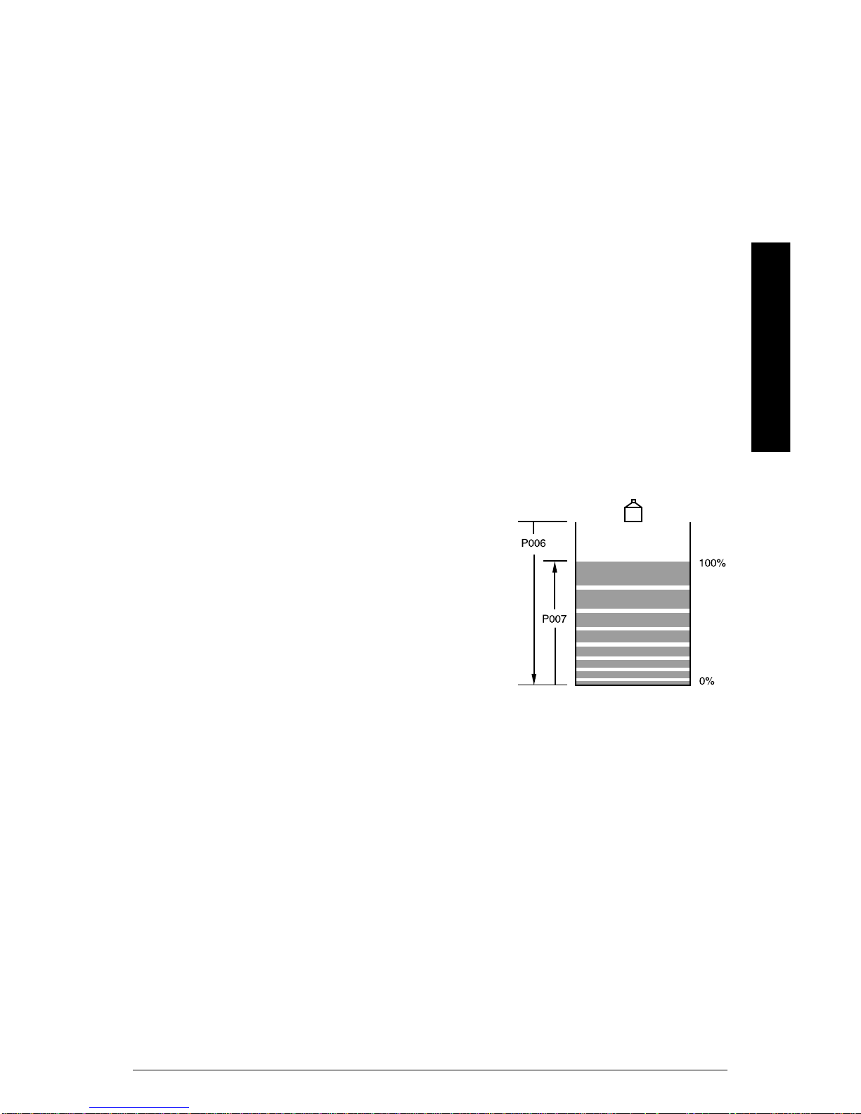
P006 (IT) Empty
Parameter Reference
The distance in “units” from the face of the transducer to the process empty
point.
Setting this value also sets Span (P007)
unless Span was already set to another
value.
Values
0.000 to 9999
Preset: 5.000m (or equivalent depending on
units)
Related
• P007 (IT) Span on page 60
• P800 (G) Near Blanking on page 176
PL-556 EnviroRanger Programming Reference Page 59
Page 60

P007 (IT) Span
Span is the range of levels that the equipment is set to measure.
Span is preset for a value close to the
maximum available. Enter a value that
reflects the maximum range of your
application.
Always prevent the monitored surface from
approaching within 0.33 m (1 ft) of the
transducer face as this is the minimum
blanking for most Milltronics transducers
(some require more blanking – see your
transducer manual).
Many other parameters are set as a percentage of span (even if they are
entered in units). The values of these other parameters may change if the
Parameter Reference
span is altered after installation and they are measured based on level
(upwards from Empty towards the transducer face).
All volumes are based on span so it should be set for the maximum volume
point if volume calculations are needed.
Values
0.0 to 9999
Preset: based on Empty (P006)
Related
• P800 (G) Near Blanking on page 176
• P006 (IT) Empty on page 59
• P005 (G) Units on page 59
• Volume (P050 to P055) on page 62
• P112 (IR) Relay “on” Setpoint on page 84
• P113 (IR) Relay “off” Setpoint on page 84
P008 (G) Date
Date is the current date in the format: YY.MM.DD.
The date is entered by using the numeric keypad and the
decimal “.” key. For example, to enter December 10, 1998 you
would type in the value “98.12.10”.
Page 60 EnviroRanger Programming Reference PL-556
rack or panel
display shown
Page 61

Year 2000 Compliance
00-69 Assumed to be the years 2000 to 2069
70-99 Assumed to be the years 1970 to 1999
Values
70:01:01 to 69:12:31
P009 (G) Time
Time is the current time in 24-hour format: HH.MM.SS.
The time is entered using the numeric keypad and the decimal
“.” key. For example, to enter 9:34:45 p.m. you would type in
the value “21.34.45”.
Parameter Reference
Values
00:00:00 to 23:59:59
rack or panel
display shown
PL-556 EnviroRanger Programming Reference Page 61
Page 62

Volume (P050 to P055)
To enable the EnviroRanger to show readings based on vessel or wet well
volume (rather than level) use these parameters.
If one of the “universal” tank shapes is used then follow this procedure:
• Plot a volume to height chart
• Enter the curve values from this chart into P054 and P055
• Ensure extra points are added around sharp transitions in the chart/reservoir
Parameter Reference
If you require volume display only (based on linear multiplication of span)
then use P061 (IT) Convert Reading on page 66. This method does not
calculate volume and must not be used in place of these parameters if any
volume dependent features (such as pump efficiency) are used.
P050 (G) Tank Shape
Enter the Tank Shape value that matches the monitored vessel or wet well.
When Operation is "level" (P001 = 1), liquid (material) volume is calculated.
Alternatively, when Operation is "space" (P001 = 2), remaining vessel
capacity is calculated.
In the RUN mode, Readings are displayed in percent maximum volume. To
convert Readings to volumetric units, see Max Volume (P051).
Page 62 EnviroRanger Programming Reference PL-556
Page 63

Values
0 = volume calculation not required (preset)
1 = flat level bottom 4 = half sphere bottom 8 = sphere
A
A
A
2 = cone / pyramid bottom 5 = flat sloped bottom 9 = universal linear
A
3 = parabola bottom
6 = flat ends
10 = universal curved
AL
7 = parabola ends
Related
• P051 (G) Max Volume on page 63
• Pump Efficiency (P180 to P186) on page 105
• P001 (G) Operation on page 57
• Pumped Volume Totalizer (P622 to P623) on page 148
• P920 (IL) Reading Measurement on page 193
Parameter Reference
P051 (G) Max Volume
For Readings in volumetric units (rather than percent), enter the vessel
volume between Empty (P006) and Span (P007).
The units of measurement for this reading are arbitrary. The volume is
calculated from the empty position to the maximum span position and is
scaled according to the Tank Shape (P050) value. This enables the use of
any volume units required.
Note:
Ensure that the chosen units allow the total volume to be displayed in the
four digits on the LCD.
Example
1. If max. volume = 3650 m
2. If max. volume = 267500 gallons, enter 267.5 (1000's of gallons).
PL-556 EnviroRanger Programming Reference Page 63
3
, enter 3650.
Page 64

Values
0.0 to 9999
Preset: 100.0
Related
• P006 (IT) Empty on page 59
• P007 (IT) Span on page 60
• P060 (IT) Decimal Position on page 66
P052 (G) Tank Dimension ‘A’
This is dimension ‘A’ as used in P050 (G) Tank Shape on page 62.
Enter the height of the tank bottom if P050 = 2,3,4, or 5, or the length of one
end section of the tank if P050 = 7, in Units (P005).
Values
0.000 to 9999
Parameter Reference
Preset: 0.000
P053 (G) Tank Dimension ‘L’
This is dimension ‘L’ as used in P050 (G) Tank Shape on page 62.
Enter the tank length (excluding both end sections) if P050 = 7.
Values
0.000 to 9999
Preset: 0.000
P054 (IB) Breakpoint Levels (Universal Volume
Calculation)
When the tank shape is too complex for any of the preconfigured shapes
you can specify the volume based on segments.
Enter up to 10 level breakpoints (where volume is known) if P050 = 9 or 10.
These values should be provided by the tank manufacturer.
To enter a Level Breakpoint...
1. Go to Parameter P054
2. For each index enter a breakpoint in measurement units
3. Ensure that each breakpoint corresponds to the same index for P055
Values
0.000 to 9999
Page 64 EnviroRanger Programming Reference PL-556
Page 65

P055 (IB) Volume Breakpoints (Universal Volume
Calculation)
Each segment defined by the level breakpoints (P055) requires a volume to
allow the EnviroRanger to make the level-to-volume calculations.
These values should be provided by the tank manufacturer.
Some typical volume calculations are:
Sphere
Cone
Cylinder
Enter the volume corresponding to each Level Breakpoint entered.
To enter a Volume Breakpoint...
1. Go to Parameter P055
2. For each index enter a volume
3. Ensure that each volume corresponds to the same index for P054
Values
0.0 to 9999
Preset: 0.000
V = (4/3)πr
V = (1/3)πr2h
V=πr2h
3
Parameter Reference
PL-556 EnviroRanger Programming Reference Page 65
Page 66

Display and Reading (P060 to P062)
Alter the following parameters to:
• Change the number of decimal places displayed
• Convert the Reading to alternate units
• Reference measurements to other than Empty (P006) or Span (P007)
P060 (IT) Decimal Position
Defines the maximum number of decimal places used on the LCD.
In the RUN mode, the number of decimal places displayed is automatically
adjusted (if necessary) to prevent the number of digits from exceeding the
display capabilities (4 digits). To keep the decimal place from shifting, and
make reading the display easier, reduce the number of decimal places to the
number shown at 100%.
Parameter Reference
For example, if 100% equals 15 metres then use two decimal places to allow
for readings such as 15.00 or 12.15.
This value is automatically altered when Units (P005) or Max Volume (P051)
is altered.
Values
0 no digits after the decimal point
1 1 digit after the decimal point
2
3 3 digits after the decimal point (limited by device resolution)
Related
• P005 (G) Units on page 59
• P051 (G) Max Volume on page 63
• P920 (IL) Reading Measurement on page 193
*
2 digits after the decimal point
P061 (IT) Convert Reading
Multiplies the current value by the specified amount to allow for any scaling
required.
Examples:
• If the measured value is in feet enter 0.3 to display the number of yards
• For simple linear volume conversions you can enter the volume
measurement per unit to get the correct conversion. For example, if the
reservoir contains 100 litres per vertical meter, use 100 to get the reading in
liters.
Page 66 EnviroRanger Programming Reference PL-556
Page 67

This method does not calculate volume and must not be used in place of the
volume parameters if any volume dependent features (such as pump
efficiency) are used. To calculate true volumes see Volume (P050 to P055)
on page 62.
Avoid entering a value that, when multiplied by the maximum current
Reading, could exceed five digits before the Decimal Position or the device
will not display the value correctly.
If a value does exceed five digits then the value “EEEE” is displayed.
Values
-999 to 9999
Preset: 1.000
Related
• P920 (IL) Reading Measurement on page 193
P062 (IT) Offset Reading
Adds the specified value to the level reading, usually to reference the
reading to sea level or another datum level.
The operation of the device is not affected by the Offset Reading. This value
is used for display purposes only. All control measurements are still
referenced to Empty.
Example
To reference the displayed level to sea level, enter the distance in Units
(P005), between Empty (P006) and sea level. (Enter a negative value if
Empty is below sea level.)
Parameter Reference
sea level
Values
-999 to 9999
Preset: 0.000
PL-556 EnviroRanger Programming Reference Page 67
P006
P007
P062
reservoir
Page 68

Related
• P920 (IL) Reading Measurement on page 193
Parameter Reference
Page 68 EnviroRanger Programming Reference PL-556
Page 69

Failsafe (P070 to P072)
The failsafe parameters are used to ensure that if no valid level reading is
available then the devices controlled by the EnviroRanger default to an
appropriate state.
By default, if an error condition is detected then the display and relay status
are held at their last "known" values and the Failsafe Timer (see below) is
activated. If the Failsafe Timer expires and the unit is still in an error
condition then P071 (IT) Failsafe Material Level determines the level
reading.
Control the reaction of the EnviroRanger to extended error conditions by
configuring parameter P071 (IT) Failsafe Material Level, described on page
70, and ensure that the fail state is optimal for your application.
If Failsafe Operation activates frequently, seeAppendix B – Troubleshooting
on page 205.
P070 (G) Failsafe Timer
Parameter Reference
The time elapsed, in minutes, of invalid measurements before Failsafe State
is activated.
Once activated, the Failsafe state initiates the following:
1. P071 (IT) Failsafe Material Level (described on page 70) is activated as the
material level reading.
a. The unit responds to the new level as programmed (control and alarm
relays activate as defined by the programming)
b. Individual relays can have independent failsafe responses. See P129
(IR) Relay Failsafe on page 90.
2. The appropriate error is displayed:
a. LOE for loss of echo from the transducer
b. Short for a shorted transducer cable
c. Open for a cut transducer cable
d. Error for all other problems
When modifying the preset value, use one that is short enough to protect the
process but long enough to avoid false alarms. Use 0 (no delay) only for
testing purposes.
This value is automatically altered when P003 (IT) Maximum Process Speed
(page 58) is altered.
PL-556 EnviroRanger Programming Reference Page 69
Page 70

Values
0.000 to 9999
Preset: 10.00 minutes
Related
• P003 (IT) Maximum Process Speed on page 58
• P129 (IR) Relay Failsafe on page 90
P071 (IT) Failsafe Material Level
The material level reported when a Failsafe State is initiated.
There are four possible settings for this parameter:
HOLd
HI
LO
Parameter Reference
Measurement
Select the Failsafe Material Level based upon the relay operation required
during failsafe operation.
Selecting HI, LO, or HOLd
1. Press
2. Press
3. Press
Entering a Measurement
To enter a specific Failsafe Material Level within -50 to 150% of Span
(P007), in Units (P005) or % of Span.
Relay reaction
The way in which relay programming reacts to the failsafe level depends on
P129 (IR) Relay Failsafe (page 90 ). By default:
to display the Auxiliary Function symbol,
or as required to scroll to the desired option,
to enter the value.
Keep the last known material level
Use the full Span (P007) as the material level
Use Empty (P006) as the material level
Use an arbitrary value (between 0 and 150% of span)
• Alarm relays have P129 = “OFF” and so react to the Failsafe Material Level.
• Control relays (all pumps and some others) have P129 = “dE” and so de-
energize the relay when the unit enters Failsafe mode regardless of the
Failsafe Material Level.
Values
0.000 to 9999 Value in units or % (to 150% of span)
HI Level goes to maximum span
LO Level goes to 0 span (Empty)
HOLd * Level remains at last reading
Page 70 EnviroRanger Programming Reference PL-556
Page 71

Related
• P001 (G) Operation on page 57
• P006 (IT) Empty on page 59
• P007 (IT) Span on page 60
• P111 (IR) Relay Control Function on page 74
• P112 (IR) Relay “on” Setpoint on page 84
• P113 (IR) Relay “off” Setpoint on page 84
• P129 (IR) Relay Failsafe on page 90
P072 (IT) Failsafe Level Advance
The speed at which the EnviroRanger advances to and returns from the
Failsafe Material Level.
When "Restricted" (preset), the EnviroRanger advances to/from the Failsafe
Material Level, as determined by Maximum Process Speed (P003) or the
Max Fill / Empty Rate (P700/P701) values entered.
When "Immediate" is selected, the Failsafe Material Level is assumed
immediately.
Parameter Reference
When "Fast Back" is selected, the Failsafe Level Advance is restricted,
however the return to a new measured material level is immediate.
Values
1 * Restricted
2 Immediate
3 Fast Back
Related
• P003 (IT) on page 58
• P700 (G) Max Fill Rate on page 159
• P701 (G) Max Empty Rate on page 159
• P070 (G) Failsafe Timer on page 69
• P071 (IT) Failsafe Material Level on page 70
PL-556 EnviroRanger Programming Reference Page 71
Page 72

Relays (P100 to P119)
The EnviroRanger comes with five relays, sometimes called digital outputs,
typically used to control devices and alarms. While the number of devices
directly controlled is limited by the relays all control functions are accessible
through software. Refer to the EnviroRanger Communications Reference for
information on accessing information through software.
Each parameter is indexed to the five relays. See Special Parameters on
page 19 for more information.
Preset Applications (P100)
The EnviroRanger makes standard applications easier to program by
providing an extensive list of presets.
Control Functions (P111)
Each relay can be configured independently to take advantage of the
flexibility built into the EnviroRanger. Configure the relays independently to
Parameter Reference
take advantage of the advanced features of the EnviroRanger. Start with a
preset application and then change only the required parameters to make
the task more efficient.
Setpoints (P112, P113, P114, P115)
Each relay is triggered by one or more setpoints. The setpoints can be
based on absolute level (P112, P113), rate of change (P702, P703), or time
(P114, P115). Each different control function specifies which setpoints are
required.
P100 (G) Preset Applications
There are six preset applications which can help configure the EnviroRanger
for typical use or for bench testing before commissioning.
If your application is similar to those listed here then select the appropriate
one and then change only the parameters required. If none of these preset
applications suits your needs then move on to P111 (IR) Relay Control
Function on page 74.
Note:
Programming the relays independently is the most common method used.
For screen applications (P100=5) the EnviroRanger’s operation must be set
to difference (P001=4).
Page 72 EnviroRanger Programming Reference PL-556
Page 73

Parameters Affected by Pre-set Applications
Value # Parameters affected
Off
Wet Well 1
Wet Well 2
Reservoir 1
Reservoir 2
Screen
(P001=4
only)
Alarms
0 All relays set “off”
Pump down with the following level settings:
Parameter
1
P111 52 52 1 (H) 1 (L) 0
12345
P112 70% 80% 90% 10% –
P113 20% 20% 85% 15% –
Pump down with the following level and rate settings:
Parameter
12345
P111 52 52 1 (H) 1 (L) 0
2
P112 80% 80% 90% 10% –
P113 20% 20% 85% 15% –
P121 1
Because the pumps are started by rate you must change
P702 and P703 to appropriate values.
Pump up with the following level settings:
Parameter
3
P111 52 52 1 (H) 1 (L) 0
12345
P112 30% 20% 90% 10% –
P113 80% 80% 85% 15% –
Pump up with the following level and rate settings:
Parameter
12345
P111 52 52 1 (H) 1 (L) 0
4
P112 20% 20% 90% 10% –
P113 80% 80% 85% 15% –
P121 1
Because the pumps are started by rate you must change
P702 and P703 to appropriate values.
Differential control of a screen or rake:
Parameter
5
P11031230
12345
P111 50 1 (H) 1 (L) 1 (H) –
P112 80% 90% 10% 90% –
P113 20% 85% 15% 10% –
General alarms at four setpoints:
Parameter
6
P111 1(H) 1(L) 1(HH) 1(LL) 0
12345
P112 80% 20% 90% 10% –
P113 75% 25% 85% 15% –
Relay #
Relay #
Relay #
Relay #
Relay #
Relay #
Parameter Reference
PL-556 EnviroRanger Programming Reference Page 73
Page 74

P110 (IR) Level Source
The level source on which the indexed relay matches setpoints.
This value is reset if Relay Set Up (P100) is altered. Points 2 and 3 are
available only if Operation is set for difference or average (P001 = 4 or 5).
Values
1 * Point # 1 = transducer 1
2 Point # 2 = transducer 2
3 Point # 3 = difference (P001=4) or average (P001=5)
Related
• P001 (G) Operation on page 57
P111 (IR) Relay Control Function
The control algorithm used to trip the relay.
Parameter Reference
Use 0 (preset) to disable control of the indexed relay.
Complete table of values on next page.
Page 74 EnviroRanger Programming Reference PL-556
Page 75

Values
Control Type #
General Off 0 Relay set off, no action
Level 1 based on level setpoints “on” and “off”
In Bounds 2
Out of Bounds 3
Rate of Change 4 based on rate setpoints “on” and “off”
Alarm
page 76
Temperature 5
Loss of Echo (LOE) 6 when echo is lost
Cable Fault 7 when the circuit to a transducer is opened
Pump Efficiency 8 based on pump volume calculations (P512)
Time of Day 9 based on the clock
Clock Failure 10 if the clock module fails
Pump Failure 11 based on P510
Power F ailure 12 based on P519
Flow
page 79
Totalizer 40 every 10yunits (P640-P645)
Flow Sampler 41
Fixed Duty Assist 50
Fixed Duty Backup 51
Alternate Duty Assist 52
Pump
page 80
Alternate Duty
Backup
Service Ratio Duty
Assist
Service Ratio Duty
Backup
First In First Out
(FIFO)
Time 60 based on “duration” and “interval” setpoints
Overflow 61 based on overflow event.
Aeration 62
Control
Gate 63
page 82
Flush Valve 64
Communication 65
4
Relay Control
when level enters the range between “on”
and “off” setpoints
when level exits the range between “on” and
“off” setpoints
based on temperature setpoints “on” and
“off”
y
every n x 10
units (P641-P645) or time
duration (P115)
at fixed “on” and “off” setpoints and allows
multiple pumps to run
at fixed “on” and “off” setpoints and allows
only one pump to run
at rotating “on” and “off” setpoints and allows
multiple pumps to run
at rotating “on” and “off” setpoints and allows
53
only one pump to run
on service ratio at “on” and “off” setpoints
54
and allows multiple pumps to run
on service ratio at “on” and “off” setpoints
55
and allows only one pump to run
as Alternate Duty Assist, resets the relay
56
from staggered “off” setpoints.
based on “duration” and “interval” setpoints
timed from when pump relays shut off
used to drive a gate based on “on”, “interval”,
and “duration” setpoints
used to control a pump flushing device
based on Flush Systems (P170 to P173)
based on input from external
communications. See the EnviroRanger
Communications Reference for further
information.
Parameter Reference
4
When reading and setting this parameter through Modbus or SmartLinx
communications the parameter values are mapped to different numbers. See the
EnviroRanger Communications Reference (PL-558) for Modbus information and the
appropriate SmartLinx manual for SmartLinx information.
PL-556 EnviroRanger Programming Reference Page 75
Page 76

P111 (IR) Alarms (values 0-12)
EnviroRanger alarm relays are normally closed but can be adjusted using
P118 (IR) Relay Output Logic on page 86.
Power Failure
When power is cut to the EnviroRanger its relays fail in the following states:
Rack or Panel Mount Wall Mount
Relay Fail State Relay Fail State
1-4 Open 1-4 Open
5 Closed 5 Open or Closed
When programming the Rack or Panel versions to use relay 5 as a general
alarm indicator, set P118 (IR) Relay Output Logic to value “3 – negative
logic” and wire the alarm for normally open operation. When an alarm event
occurs (described below) or when power is cut to the EnviroRanger the
circuit closes and the alarm sounds.
Parameter Reference
LCD Status Indicators
5
Alarm off
Relay contact closed
P118 as preset
Alarm on
Relay contact open
P118 as preset
Level (1)
High level alarm
set the “on” setpoint (P112) above “off” setpoint (P113) in units (P005) or
percent of span (P007).
Low level alarm
set the “on” setpoint (P112) below the “off” setpoint (P113) in units (P005) or
percent of span (P007).
Level alarms can show other icons on the LCD if they are given a
designation. The designation identifies the different alarms on the LCD and
through communications.
Designation Purpose LCD Icon Setpoints
(blank) no indicator none as desired
HH “Hi Hi” Alarm
H High Alarm
LLowAlarm
LL “Lo Lo” Alarm
P112 > P113
P112 > P113
P112 < P113
P112 < P113
5
Relay 5 is a Form C type on the Wall mount so you can wire it either normally open
or normally closed. Check the wiring before programming.
Page 76 EnviroRanger Programming Reference PL-556
Page 77

To select a Level Alarm Designation (L,LL,H,HH or blank)...
1. Press
2. Press
3. Press
to display the Auxiliary Function symbol,
or as required to scroll to the alarm designation,
to enter the value.
In Bounds (2)
Use the “on” setpoint (P112)
to define the top of the
bounded area. Use the “off”
setpoint (P113) to define the
bottom of the bounded area.
Use P116 (IR) Dead Band on
page 86 to define the actual
“on” and “off” setpoints
around each boundary.
Out of Bounds (3)
Use the “on” setpoint (P112)
to define the top of the
bounded area. Use the “off”
setpoint (P113) to define the
bottom of the bounded area.
Use P116 (IR) Dead Band on
page 86 to define the actual
“on” and “off” setpoints
around each boundary.
setpoint
“on” P112
setpoint
“off” P113
setpoint
“on” P112
setpoint
“off” P113
dead band
P116
dead band
P116
dead band
P116
dead band
P116
Parameter Reference
Rate of Change (4)
Use the “on” setpoint to define the filling or emptying rate at which the alarm
is tripped. This setpoint can be in:
• percent of span per minute
• units per minute
Filling alarm
set the “on” and “off” setpoints as positive numbers
Emptying alarm
set the “on” and “off” setpoints as negative numbers
Any rate of change alarms must be set equal to or lower than the
appropriate rate parameters or they will never trip. Check:
• P700 (G) Max Fill Rate on page 159
• P701 (G) Max Empty Rate on page 159
filling “on”
and “off”
emptying “on”
and “off”
(negative
numbers)
PL-556 EnviroRanger Programming Reference Page 77
Page 78

Temperature (5)
Use the “on” and “off” setpoints to define the temperatures to trip and reset
the alarm relay. All temperatures are specified in °C.
Loss of Echo (6)
Use the loss of echo (LOE) alarm to trip a relay when the device fails to read
echos. The timer for this fault is P070 (G) Failsafe Timer on page 69.
Transducer Cable Fault (7)
Use the cable fault alarm to trip a relay when the device detects an open or
short circuit on a transducer.
Pump Efficiency (8)
Use the pump efficiency alarm to trip a relay when calculated pump
Parameter Reference
efficiency falls. See Pump Efficiency (P180 to P186) on page 105 for details
on how this alarm is set up.
Time of Day (9)
Use the time of day alarm to trip a relay at the same time every day. Use
the following two parameters to set when the alarm is tripped and for how
long:
• P146 (IR) Time of Day Setpoint on page 98
• P114 (IR) Relay “duration” Setpoint on page 85
Clock Failure (10)
Use the clock failure alarm to trip a relay if the clock module fails.
Pump Failure (11)
Uses the status of P510 (IR) Pump Failed Status on page 134 to trip an
alarm relay. The failure of any pump results in an alarm.
The alarm relay is reset when the status parameter is reset.
Power Failure (12)
Uses the status of P519 (V) Power Failure Status to trip an alarm relay.
When the power returns and P519 resets the alarm is reset.
Page 78 EnviroRanger Programming Reference PL-556
Page 79

P111 (IR) Flow Totals (values 40-41)
33m31m32m32m3
EnviroRanger pump relays are normally open but can be adjusted using
P118 (IR) Relay Output Logic on page 86.
LCD Status Indicators
Normal
Relay contact open
P118 as preset
Totalizer pulse (momentary)
Relay contact closed
P118 as preset
The relay is activated by units of totalized flow from Pumped Volume or
OCM:
Pumped Volume (P001=7)
Calculates volume based on wet well draw down and pump run times. See
Pumped Volume Totalizer (P622 to P623) on page 148 for details.
Multiple Contacts
Pumped volume is calculated at the end of the pump cycle. Totalized volume
given through a relay set up for “totalizer (40)” will be given in bursts at this
time. Both the open and closed times for the relay contact are provided by
P645 and are preset to 0.2 seconds. Partial units are added to the next
pump cycle.
Example
P645
P645
Parameter Reference
4m
pump
cycle
The example shows a relay set up to make 1 contact for every cubic metre
3
(m
) of liquid.
OCM (P001=6)
Calculates volume based on flow over the primary measuring device. See
Open Channel Monitoring (OCM) on page 32 for details.
Totalizer (40)
Use the totalizer to provide relay contact to an external counter using the
following formula:
P640
1 Contact per 10
P640 is preset to “0” so the default number of contacts for a pumped volume
cycle is equivalent to P051 (G) Max Volume.
units
PL-556 EnviroRanger Programming Reference Page 79
Page 80

The source of units varies depending on the operation:
Operation Units Source Parameter
OCM (P001=6)
P604 (G) Maximum Flow on page 143
P608 (G) Flowrate Units on page 145
Pumped Volume (P001=7) P051 (G) Max Volume on page 63
Related
• P640 (G) Remote Totalized Multiplier on page 151
• P645 (G) Relay Duration on page 152
• P051 (G) Max Volume on page 63
• P645 (G) Relay Duration on page 152
Flow Sampler (41)
A liquid flow sampler, as supported by the EnviroRanger, is a device which
removes some liquid from a flow and stores it for later testing. To trigger a
flow sampler based on volume use this value (P111=41). To trigger a flow
Parameter Reference
sampler based on time use the Time control (P111=60).
The flow sampler triggers the relay by the following algorithm:
P642
1 Contact per P641 x 10
units
Operation Units Source Parameter
OCM (P001=6)
P604 (G) Maximum Flow on page 143
P608 (G) Flowrate Units on page 145
By using a mantissa (P641) and an exponent (P642) the relay contacts can
be based on a volume other than a multiple of ten.
Related
• P641 (G) Flow Sampler Mantissa on pag e 151
• P642 (G) Flow Sampler Exponent on page 152
• P645 (G) Relay Duration on page 152
P111 (IR) Pumps (values 50-56)
For a comprehensive description of the available pump control strategies
see Appendix C – Pump Control on page 215.
EnviroRanger pump relays are normally open but can be adjusted using
P118 (IR) Relay Output Logic on page 86.
Pump Down (wet well)
set the “on” setpoint (P112) above the “off” setpoint (P113) in units (P005) or
percent of span (P007).
Page 80 EnviroRanger Programming Reference PL-556
Page 81

Pump Up (reservoir)
set the “on” setpoint (P112) below the “off” setpoint (P113) in units (P005) or
percent of span (P007).
LCD Status Indicators
Pump off
Relay contact open
P118 as preset
Pump on
Relay contact closed
P118 as preset
Values
Duty Assist Backup
Fixed
Alternate
Service
FIFO
50 51
52 53
54 55
56 –
Discrete inputs can be used to remove pumps from the duty schedule. See
Pump Interlock Allocation (P500 to P509) on page 128 for details.
Assist (50, 52, 54, 56)
When more than one pump is started they run simultaneously.
Backup (51, 53, 55)
AWordonPumpRotation
When more than one pump is started the
previously running pump is switched off. Only
one pump at a time is ever running.
Fixed (50, 51)
The “on” and “off” setpoints remain static (as
programmed) for each pump relay.
Alternate (52, 53)
The “on” and “off” setpoints are shared for
the pump group and are rotated each time
the material level cycles.
Service (54, 55)
The “on” and “off” setpoints are shared for
the pump group and pumps are started in
order of run time based on a user-defined
ratio. Ratios are specified using P122 (IR)
Pump Service Ratio on page 89.
The EnviroRanger groups
pumps together based on the
Relay Function and the
indexed transducer.
If there are four pumps
indexed to a single transducer
with two pumps assigned
value 52 and two pumps
assigned value 54 then the
EnviroRanger groups both
“52’s” and both “54’s” and
performs the rotation on each
group separately.
If all four pumps were
assigned value “52” then all
four would be grouped and
rotation would happen on all
four. The only way to
circumvent this grouping is to
use P137 (IR) Pump Group
on page 52).
Parameter Reference
PL-556 EnviroRanger Programming Reference Page 81
Page 82

FIFO (56)
The “on” and “off” setpoints are shared for the pump group and pumps are
started using the alternate algorithm but are shut off using the “first in, first
out” rule.
“Off” setpoints are generally staggered.
Note:
Do not use “FIFO” pump sequencing with volume totalization because for
totalization to work all of the pump “off” setpoints must be the same.
P111 (IR) Control (values 60-65)
EnviroRanger control relays are normally open but can be adjusted using
P118 (IR) Relay Output Logic on page 86.
Parameter Reference
LCD Status Indicators
Control off
Relay contact open
P118 as preset
Control on
Relay contact closed
P118 as preset
Values
Function Description Setpoints
Time relay operation on elapsed time P114, P115, P645
Overflow relay operation on overflow conditions P160-P165
Aeration timed relay operation if pumps off P114, P115
Gate timed relay operation triggered by level P112, P114, P115
Flush Valve timed relay operation on pump cycles P170-P173
Communication relay operation controlled remotely
Time (60)
Use the "Time Control" R elay Function to activate a device based upon
elapsed time.
e.g. Timed rake control to keep ram lubricated if idle for long periods or
prevent ice build up in winter.
Page 82 EnviroRanger Programming Reference PL-556
Page 83

Overflow (61)
Use the "Overflow Control" Relay Function to activate a device based upon
high levels associated with Overflow conditions.
e.g. Open gate (valve) to divert overflow into a holding vessel and optionally
turn off pumps. See Overflow / Underflow (P160 to P169) on page 99
for details.
Aeration (62)
Use the "Aeration Control" Relay Function to activate a device based upon
elapsed time since all pumps have been "OFF".
e.g. Timed fresh air introduction to reduce gas concentration or aerate
sewage in a wet well.
Gate (63)
Use the "Gate Control" Relay Function (EnviroRanger relays 1 and 2 only) to
activate a drive motor for a specific time if level is outside a specified band.
Both relays must be used to control the gate (penstock), one for opening and
one for closing.
SeeGateControlonpage44formoreinformation.
e.g. Maintain constant level by time-step adjusting upstream gate based on
downstream head.
Flush Valve (64)
Parameter Reference
Use the "Flush Valve" Relay Function to activate a device for a specific time
based upon pump cycle frequency.
e.g. Re-circulate into wet well periodically to stir up bottom solids so that
they will be pumped out.
Communication (65)
Use the “Communication” Relay Function to control the relay from an
external device. This device communicates with the EnviroRanger using the
built in Modbus protocol or optional SmartLinx card.
e.g. Control EnviroRanger relays via a digital communications port from a
remote PC running a SCADA package.
PL-556 EnviroRanger Programming Reference Page 83
Page 84

P112 (IR) Relay “on” Setpoint
The process point at which the relay changes from its “normal” state.
For most applications this is the point at which the relay is tripped. For “inbounds” and “out-of-bounds” alarms it is the high point in the specified
range.
This parameter is set according to Span (P007) even when another reading,
such as volume, is shown on the LCD.
Values
-999 to 9999
Preset: ----
Related
• P100 (G) Preset Applications on page 72
• P111 (IR) Relay Control Function on page 74
Parameter Reference
• P113 (IR) Relay “off” Setpoint on page 84
P113 (IR) Relay “off” Setpoint
The process point at which the relay returns to its “normal” state.
For most applications this is the point at which the rela y is reset. For “inbounds” and “out-of-bounds” alarms it is the low point in the specified range.
This parameter is set according to Span (P007) even when another reading,
such as volume, is shown on the LCD.
Values
-999 to 9999
Preset: ----
Related
• P100 (G) Preset Applications on page 72
• P111 (IR) Relay Control Function on page 74
• P112 (IR) Relay “on” Setpoint on page 84
Page 84 EnviroRanger Programming Reference PL-556
Page 85

P114 (IR) Relay “duration” Setpoint
The length of time in minutes the relay is to be energized.
This value must be less than the “interval” setpoint or the relay will never
reset.
P114
(min.)
P115
(hours)
Values
0.000 to 9999
Preset: ----
Related
• P100 (G) Preset Applications on page 72
• P111 (IR) Relay Control Function on page 74 (P111=9,60,62,63)
• P115 (IR) Relay “interval” Setpoint on page 85
• P134 (IR) Pump Exercising on page 93 (P111=50 to 56)
Parameter Reference
P115 (IR) Relay “interval” Setpoint
The length of time in hours between timed starts.
This value must be greater than the “duration” setpoint or the relay will never
reset.
P114
(min.)
P115
(hours)
Values
0.000 to 9999
Preset: ----
Related
• P100 (G) Preset Applications on page 72
• P111 (IR) Relay Control Function on page 74 (P111=9,60,62,63)
• P114 (IR) Relay “duration” Setpoint on page 85
• P134 (IR) Pump Exercising on page 93 (P111=50 to 56)
PL-556 EnviroRanger Programming Reference Page 85
Page 86

P116 (IR) Dead Band
The distance above and below the bound alarm setpoints which actually
energizes and de-energizes the alarm relays.
For “in-bounds” and “out-of-bounds”
Relay Functions (P111 = 2 and 3
respectively) a dead band prevents
relay chatter due to material level
fluctuations at both the upper and
lower setpoints.
actual “on” or
“off” setpoint
P116
setpoint as set in
P112 or P113
P116
actual “off” or
“on” setpoint
Enter the dead band in either percent of span or units of measure (P005).
The dead band value is applied both above and below the upper and lower
bound setpoints as shown in the figure.
Parameter Reference
Values
0.000 to 9999
Preset: 2% of span
Related
• P100 (G) Preset Applications on page 72
• P111 (IR) Relay Control Function on page 74
• P112 (IR) Relay “on” Setpoint on page 84
• P113 (IR) Relay “off” Setpoint on page 84
P118 (IR) Relay Output Logic
The logic applied to relays to determine the contact open or closed state.
The relay contact operation is “normally closed” for alarms and “normally
open” for controls. See P111 (IR) Relay Control Function for more
information.
Power Failure
When power is cut to the EnviroRanger its relays fail in the following states:
Rack or Panel Mount Wall Mount
Relay Fail State Relay Fail State
1-4 Open 1-4 Open
5 Closed 5 Open or Closed
6
Relay 5 is a Form C type on the Wall mount EnviroRanger so you can wire it either
normally open or normally closed. Check the wiring before programming.
6
Page 86 EnviroRanger Programming Reference PL-556
Page 87

To use relay 5 as a general alarm indicator, set P118 to value “3 – negative
logic” and wire the alarm for normally open operation. When an alarm event
occurs (described below) or when power is cut to the EnviroRanger the
circuit closes and the alarm sounds.
Positive Logic
In software all relays are programmed the same way, with “on” setpoints
indicating when to change the relay contact state (open or closed). This
parameter allows the reversal of the operation so that relay contacts can be
“normally closed” or “normally open.” P118 is preset to “2” which is positive
logic.
Negative Logic
When P118 = 3 (negative logic) the operation for the indexed relay is
reversed from normal.
Values Logic Alarm Contact Pump or Control Contact
2 * positive logic Normally Closed Normally Open
3 negative logic Normally Open Normally Closed
Parameter Reference
Related
• P111 (IR) Relay Control Function on page 74
P119 (IR) Relay Logic Test
Forces the relay control logic into an “activated” or “de-activated” state.
Use this parameter to test your site wiring and control logic programming.
Forcing the relay to an activated or de-activated state is similar to the
EnviroRanger detecting an event and responding to it. This is helpful in
testing new installations and diagnosing control problems.
Values
0 * off – control from EnviroRanger algorithms
1 activate relay control
2 de-activate relay control
Related
• P111 (IR) Relay Control Function on page 74
PL-556 EnviroRanger Programming Reference Page 87
Page 88

Pump Setpoint Modifiers (P121 and P122)
These parameters provide alternate ways of starting the pumps in the pump
group. See Appendix C – Pump Control on page 215 for descriptions of the
pump control algorithms.
P121 (G) Pump by Rate
Sets the pump relays to accept control by rate of level change once the first
“on” setpoint is reached.
Use this function when there are multiple pumps which should be controlled
by rate of level change rather than setpoints. Pumping costs can be less
because only the highest “on” setpoint needs to be programmed and this
resultsinalowerdifferenceinheadtothenextwetwellwhich,inturn,
results in less energy being used to pump out the well.
Parameter Reference
When the first “on” setpoint is reached the pumps will start, one by one, until
the material level is changing at a rate the same or greater than the one
specified in:
• P703 (G) Emptying Indicator on page 160 (pump down application)
• P702 (G) Filling Indicator on page 160 (pump up application)
The delay between pump starts is set by P132 (G) Pump Start Delay on
page 92.
This parameter only applies to any relays set to pump control (P111 = 50 to
56).
Notes:
• All pump control relay “on” and “off” setpoints must be set to the same
value.
• If the level is within 5% of Span (P007) of the “off” setpoint then the
next pump is not started.
Values
0 * off (pump by level)
1 on (pump by rate)
Related
• P007 (IT) Span on page 60
• Rate (P700 to P708) on page 159
• P111 (IR) Pumps (values 50-56) on page 80
Page 88 EnviroRanger Programming Reference PL-556
Page 89

P122 (IR) Pump Service Ratio
Selects pump usage based on the run time ratio rather than last used.
This parameter only relates to relays with P111=54 or 55.
To make this parameter useful, assign it to all of the pump relays. The
number assigned to each pump relay represents the ratio that is applied
when determining the next pump to start or stop.
Example
Pump Assigned Relay Service Ratio
112
221
This service ratio would run pump one twice as often as pump two.
Notes:
• The EnviroRanger will not sacrifice other pumping strategies to ensure
that the ratio is held true.
• If the pump relays are set to the same value then the ratio equals 1:1
and all pumps are used equally (preset).
Parameter Reference
Use this feature to predetermine pump usage if a "Pump Service Ratio"
Relay Function (P111 = 54 or 55) is selected.
When more than one pump is assigned a Pump Service Ratio value (in any
time units) and a pump start is required (Relay Setpoint “on”, P112), the
pump with the least running hours (with respect to the assigned ratio values)
is started.
Conversely, when a pump stop is required (Relay Setpoint “off” (P113), the
pump with the most running hours (as compared to the assigned ratio
values), stops.
Values
0.000 to 9999
Preset: 20.00
Related
• P111 (IR) Relay Control Function on page 74
• Service on page 81
PL-556 EnviroRanger Programming Reference Page 89
Page 90

Independent Relay Failsafe (P129)
P129 (IR) Relay Failsafe
Sets the failsafe operation per relay to allow for more flexible programming.
Use this feature for rela y failsafe operation independent from the Failsafe
Material Level (P070).
Relay Failsafe is only available for the following rela y functions (P111).
Relay Function (P111) Preset (P129)
1 – level alarm
2 – in bounds alarm
3 – out of bounds alarm
4 – rate of change alarm
5 – temperature alarm
Parameter Reference
9 – time of day alarm
50 to 56 – all pump controls dE
OFF
Relay Failsafe is not used for any other relay control function.
To select an independent Relay Failsafe value:
1. Press
2. Press
3. Press
Values
OFF *
HOLd for "last known" relay state retention
dE * to have the relay de-energize immediately on failsafe
En to have the relay energize immediately on failsafe
Related
• P070 (G) Failsafe Timer on page 69
• P111 (IR) Relay Control Function on page 74
to display to the Auxiliary Function symbol,
or to scroll to the failsafe options.
with the desired option displayed.
relay response governed by P071 (IT) Failsafe Material
Level on page 70
Page 90 EnviroRanger Programming Reference PL-556
Page 91

Advanced Pump Control Modifiers (P130 to
P136)
These parameters affect only relays set to pump operation (P111 = 50 to
56).
P130 (G) Pump Run-On Interval
Sets the number of hours between pump run-on occurrences.
One technique of clearing sediment in a “pump-down” wet well is to
occasionally run the pump, after the normal “off” setpoint is reached, to force
some of the solid material through. This parameter indicates how many
hours should elapse between pump run-on occurrences.
Only the last pump running is allowed to run-on.
Values
0.000 to 1000
Preset = 0.000
P131 (G) Pump Run-On Duration
Sets the number of seconds that the pump runs-on.
Enter the duration of pump run-on in seconds. Care must be taken when
choosing this value because the amount of material pumped out of the
reservoir will vary with the pump capacity.
Parameter Reference
Choose a value long enough to clean out the vessel bottom, yet short
enough not to run the pump dry (if that would damage the pump).
Because the duration is measured in seconds and the interval is measured
in hours overlap is highly unlikely, however, ensure that the values used do
not overlap. The timing should look something like this:
Values
0.0 to 9999
Preset = 0.000
PL-556 EnviroRanger Programming Reference Page 91
pump running time
P130
Page 92

P132 (G) Pump Start Delay
Staggers pump start times to reduce power surges.
Use this feature to reduce the power surge that would occur if all pumps
started simultaneously.
Enter the time to elapse (in seconds) after a pump has started before the
next pump is permitted to start (if called for).
Note
This value is divided by 10 when in simulation mode.
Values
0.0 to 9999
Preset: 10 seconds
Parameter Reference
Related
• P121 (G) Pump by Rate on page 88
P133 (G) Pump Power Resumption Delay
Delays the first pump restart after a power failure to reduce power surges.
Use this feature to reduce the power surge that would occur if the first pump
started immediately on power resumption.
Enter the time, in seconds, to elapse after power resumption (following a
power interruption) before the first pump is permitted to start. Once this
delay expires then the other pumps will start subject to the value specified
for P132 (G) Pump Start Delay (above).
Values
0.000 to 9999
Preset: 10 seconds
Related
• P132 (G) Pump Start Delay on page 92
Page 92 EnviroRanger Programming Reference PL-556
Page 93

P134 (IR) Pump Exercising
Reduces pump corrosion or sediment build up by running the pump if it is
idle for a long time.
If a pump remains idle for the time (in hours) specified by P115 (IR) Relay
“interval” Setpoint value entered then the pump runs for the time specified by
P114 (IR) Relay “duration” Setpoint.
Values
0*off
1 on (use P114 and P115 for timing information)
P136 (G) Wall Cling Reduction
Varies the upper and lower setpoints (Relay Setpoint “on” and “off”) to
reduce material buildup on the reservoir walls at those points.
This value is the range in which the setpoints are allowed to deviate in
percent or units.
Parameter Reference
The Relay Setpoints “on” and “off” values are randomly varied inside the
range to ensure that the material level does not consistently stop at the
same point.
level setpoint “on”
random setpoint range
wall cling value
level setpoint “off”
Values
0.000 to 9999
Preset: 0.000
PL-556 EnviroRanger Programming Reference Page 93
Page 94

P137 (IR) Pump Group
Assigns pumps to groups to allow for multiple pump rotations on one
transducer.
Use this feature to group pumps (relay points 1 - 5) into group 1 or 2.
The feature is applied to pump rotation and occurs independently within
each group. Only the following values of P111 are affected by this
parameter:
P111 Name
52 Alternate duty assist
53 Alternate duty backup
Values
1 * group 1
2group2
Parameter Reference
Page 94 EnviroRanger Programming Reference PL-556
Page 95

Pump Energy Cost Reduction (P140 to P145)
These parameters affect only relays set to pump operation (P111 = 50 to 56).
Using these parameters you can configure an EnviroRanger to maximize its
operation during periods of low energy cost and minimize its operation
during periods of high-energy cost. The methods used to achieve this are:
1. Emptying the wet well just prior to the high cost period, regardless of
material level (P141, P142, and P143)
2. Changing setpoints for high cost and low cost periods (P144 and P145)
P140 (G) Energy Saving
Maximizes pump use during periods of low energy costs and minimizes use
during periods of high-energy cost.
Values
0*off
1 on (do not pump during peak energy cost, if possible)
Parameter Reference
P141 (IB) Peak Start Times
The time of day when high-energy costs (to be avoided) start.
This value, in conjunction with Peak End Time, defines the high energy cost
period. This value is indexed by the number of high energy cost periods
required in a 24-hour span. Up to 10 periods may be programmed though
one is usually sufficient.
All times are entered in 24-hour format.
Values
HH.MM
Preset: 00:00
P142 (IB) Peak End Time
The time of day when high energy costs (to be avoided) end.
This value, in conjunction with Peak Start Time, defines the high energy cost
period. This value is indexed by the number of high energy cost periods
required in a 24-hour span. Up to 10 periods may be programmed though
one is usually sufficient.
All times are entered in 24-hour format.
PL-556 EnviroRanger Programming Reference Page 95
Page 96

All end times must have the same index value as the corresponding start
time.
Values
HH.MM
Preset: 00:00
P143 (G) Peak Lead Time
The time (in minutes) before the Peak Start Time that the EnviroRanger will
begin pumping.
Enter the estimated pump running time (in minutes) required to pump the
level from the highest Relay Setpoint “on” (P112) to the lowest Relay
Setpoint “off” (P113) levels.
This value defines the time before the high energy cost period, when the
EnviroRanger should start pumping to ensure the level is as far as possible
Parameter Reference
from the Relay Setpoint “on” (P112) level.
(If the level is already within 5% of Span from the Relay Setpoint “off” (P113)
level, no action is taken).
If multiple pump stations are series linked, ensure the Peak Lead Times
entered are sufficient to attain the desired level in all stations before the
high-energy cost period occurs.
Values
0.000 to 1440
P144 (IR) Peak “on” Setpoint
Enter the value (similar to Relay Setpoint “on”, P112) to be used for the highenergy cost period.
This feature allows the level to go beyond the normal Relay Setpoint “on”
before a pump is started.
Values
0.000 to 9999
Preset: 0.000
Page 96 EnviroRanger Programming Reference PL-556
Page 97

P145 (IR) Peak “off” Setpoint
Enter the value (similar to Relay Setpoint “off”, P113) to be used for the highenergy cost period.
This feature allows the pump(s) to be stopped before the normal Relay
Setpoint “off”, to reduce pump-running time during the high energy cost
period.
Values
0.000 to 9999
Preset: 0.000
Energy Savings Example
The following example illustrates high energy cost usage reduction and/or
elimination by utilizing the EnviroRanger Pump Energy Cost Reduction
features on a wet well (pump down application).
Parameter Reference
Normal Operation
Uses the standard “on” and “off” setpoints
(P112 / P113). Energy cost is at minimum.
Peak Lead time (P143 = 60 minutes)
Pumps down the wet well regardless of the
Relay “on” Setpoints. This ensures that the
wet well starts the high cost period at the
pumps’ “off” setpoint. Energy cost is at
minimum.
Peak Start Time (P141 = 17:30)
Starts using the energy savings setpoints
(P144 and P145). Energy cost is at
maximum.
Peak End Time (P142 = 21:30)
Returns to normal setpoints (P112 and
P113). Energy cost returns to minimum.
Note:
When the Peak “on” Setpoint is not reached, no energy is used during the
"high cost" period. If the Peak “on” Setpoint is reached, the Wet Well is
only pumped down to 60%, thereby minimizing "high cost" energy usage.
PL-556 EnviroRanger Programming Reference Page 97
Page 98

P146 (IR) Time of Day Setpoint
Use this feature to set the time at which a relay set for time day alarm
(P111=9) will trip. Enter the time in HH.MM (24 hour) format.
Values
00:00 to 23:59
Parameter Reference
Page 98 EnviroRanger Programming Reference PL-556
Page 99

Overflow / Underflow (P160 to P169)
The overflow / underflow parameters allow the EnviroRanger to react to flow
conditions caused by storms or other unusual events.
When the EnviroRanger enters a flow event the following actions are taken:
• Logging starts.
See Overflow (CSO) Records (P313 to P316) on page 119 for details.
• Relays are overridden.
See P165 (IR) Overflow / Underflow Relay Action on page 102 for details.
• Control relays are tripped.
See P111 (IR) Control (values 60-65) on page 82 for details of option “61.”
• Communications are updated.
See the EnviroRanger Communications Reference for details.
• P169 is updated.
See P169 (V) Flow Condition on page 102 for details.
When the EnviroRanger ends a flow event the logging is stopped and all
other actions are ended.
P160 (G) Overflow / Underflow Level Source
Defines the source used to detect a flow condition.
The input for the flow condition is specified as x:y where:
Parameter Reference
Input Type xvalue yvalue
Overflow :
Underflow:
For example, to configure a float to trigger an overflow event you would
connect it to one of the discrete inputs, in this example 5, and the value for
P160 would be 2:5.
PL-556 EnviroRanger Programming Reference Page 99
Transducer 1
Discrete Input 2 1 to 8 – references the DI used
Transducer 3
Discrete Input 4 1 to 8 – references the DI used
1 – transducer 1
2 – transducer 2
3 – average or difference
(P001=4 or 5)
1 – transducer 1
2 – transducer 2
3 – average or difference
(P001=4 or 5)
Page 100

Note:
You must specify the correct overflow or underflow settings for your “on”
and “off” setpoints. If these values don’t match (for example, Overflow set
as 1:1 and “on” setpoint below “off” setpoint) then no action is taken.
Use 0:0 to disable overflow logging. If either value is set to “0” then no
overflow or underflow action is enabled.
To enter a colon “:”, press the decimal “.” button on the keypad.
Values
x:y
Preset: 0:0
P161 (G) Overflow / Underflow Setpoint “on””
The point at which the flow event is triggered.
Parameter Reference
This setpoint is used only if the level source (P160) is a transducer or mA
input. If a discrete input is used to detect overflow or underflow then this
parameter is ignored.
Notes:
• For overflow events the “on” setpoint must be above the “off” setpoint
or no events are logged.
• For underflow events the “off” setpoint must be above the “on” setpoint
or no events are logged.
Values
0.000 to 9999
Preset: 0.000
P162 (G) Overflow / Underflow Setpoint “off”
The point at which the flow event is reset.
This setpoint is used only if the level source (P160) is a transducer or mA
input. If a discrete input is used to detect overflow or underflow then this
parameter is ignored.
Notes:
• For overflow events the “on” setpoint must be above the “off” setpoint
or no events are logged.
• For underflow events the “off” setpoint must be above the “on” setpoint
or no events are logged.
Page 100 EnviroRanger Programming Reference PL-556
 Loading...