

Page 1

COMPUFLO III
FLOWMETER
INTEGRATOR
Instruction Manual
PL-368
March 1993
33453680
PRR 1.1
Page 2

Page 3

TABLE OF CONTENTS
TITLE PAGE #
Gener al Inf ormation
About the CompuF lo III 1 – 1
About th is Manual
General 1 – 2
Conventions 1 – 2
Specifications
CompuFlo III 2 – 1
Options 2 – 2
Installation
CompuFlo III 3 – 1
Interconnection 3 – 1
Hazardous Locations 3 – 1
Start Up
Hardware Set Up 4 – 1
Pre Start Up Checks 4 – 3
Initial Start Up 4 – 3
Programming
Calibration
General 5 – 1
Keypad 5 – 1
Parameter Entry 5 – 2
Direct Parame ter Access 5 – 2
Automat ic Parameter Access 5 – 2
Altering Parameter Values 5 – 3
Last Parameter Recall 5 – 3
Parameter Reset 5 – 3
Programming Sequence 5 – 3
Quick Start Procedure 5 – 3
General 6 – 1
Initial Calibration References 6 – 1
Zero 6 – 2
Span 6 – 2
Calibration Accuracy 6 – 2
Calibration Alternatives 6 – 3
Auto Zero 6 – 3
Lockout Mode 6 – 3
On-Line Span Calibration 6 – 3
Alternate Test References 6 – 4
ECAL Calibration 6 – 4
PL-368 i
Page 4

Parameters
General 7 – 1
Parameters 7 – 1
Programming Chart 8 – 1
Operation
Initial Operation 9 – 1
Normal Operation
Start Up 9 – 2
Zero Calibration Check 9 – 2
Span Calibration Check 9 – 2
Reset Total 9 – 2
Run 9 – 2
Communication
General 10 – 1
Remote Com munication 10 – 2
Host Communication 10 – 2
Serial Printer Communication 10 – 2
Protocol 10 – 3
Data Field Descriptions 10 – 3
Message Requests 10 – 4
Message Responses 10 – 4
Appendices
Figures
Alphabetical Par ameter Listing 11 – 1
Maintenance and Spare Parts 11 – 2
Error Messages 11 – 3
Trouble Shooting 11 – 4
Quick Start 11 – 5
Start U p 11 – 5
Calibration 11 – 6
Operation 11 – 7
Performance Enhancement 11 – 7
FIG. 1 Outline and Mounting 12 – 1
FIG. 2 Layout 12 – 2
FIG .3 CompuFlo III / Flowmeter Interconnection 12 – 3
FIG. 4 Po wer, Auto Zero, & Rate Output Wiring 12 – 4
FIG. 5 Relay Wiring 12 – 5
FIG. 6 Communication Wiring 12 – 6
PL-368 ii
Page 5
GENERAL INFORMATION
ABOUT THE COMPUFLO
The Milltro nics CompuFlo III is a
microprocessor based integrator designed
specifically for b u lk dry solids in-line
weighing applications.
The CompuFlo III integrates a signal
proportional to material flowrate (such as
from a Milltronics flowmeter) over time to
provide material totalization.
The Com puFlo III provides:
» Rate and Total displays
» an analog mA output proportional to rate
» a relay contact f or remote total izer or PLC operation
» 2 alarm/ control relays based on rate and/or On-line Calibration
» 2 communication ports for computer , PLC, or serial printer c onnection
The CompuFlo I II has three modes of operation;
program, calib rate and run.
MULTI SPAN NO: 1R2:RATE HI R1:SPEED LO
1263957
TOTAL
T
150%100%50%0%-50%
The operator programs the CompuFlo III via the
keypad to provide displays and outputs in the
desired units of measure. The Comp uFlo III
displays the name, range of acceptable values,
(and additional information/instruction) of the
parameter (programming feature) accessed.
In the calibrate mode, the system Zero (no flow) and Span (100% flowrate) calibration is established. A test
reference (test weight) is used to simulate the force of material impacting the flowmeter sensing plate during
the Span calibration. A mater ial test is normally performed to verify the calibration accuracy. If necessary, the
material test results may be used to correct any deviation in calibration accuracy.
Calibration accuracy may be checked at any time. The results of th is check are automatically compared to the
system calibration and the deviation is displayed. The operator may choose to continue operation with the
previous calibration or the results of the calibration check.
All programming and calibration information is stored in non-volatile memor y. If desired, the security
parameter may be set to ensur e the CompuFlo III programming and calibration is not inadvertent ly altered in
the run mode.
The run mode is the normal operating mode, providing dynamic measurement displays, analog mA output,
and a variety of other features.
PL-368 1 – 1
Page 6

ABOUT THIS MANUAL
GENERAL
This instruction manual conta ins informat ion essential to successful CompuFlo III operation.
SPECIFICATIONS, includes CompuFlo III environmental, phys ical, and operational characteristics.
INSTALLATION, indicates the typical mounting and interconnection procedure.
START UP, prepares the Compu Flo III for programming.
PROGRAM MING, details activities required to ta ilor t he CompuFlo III to the par ticular application.
CALIBRATION, includes the CompuFlo III input signal to output feature corr elation procedure.
PARAMETERS, describes the function, factory setting, and range of possible settings,
of each parameter.
PROGRAM MING CH A RT, provides a space to record programmed parameter values for futur e reference.
OPERATION, describes initial and normal CompuFlo III operation.
COMMUNICATION, provides CompuFlo III serial communication information.
APPENDICES, contains Quick Start , Alphabetical Parameter L ist, Maintenance and Spare Parts,
Error Messages and Trouble Shooting information.
FIGURES, includes a complete set of installation and interconnection drawings.
CONVENTIONS
Throughout this instruction manual the following symbols and presentation practices have been utilized:
[1234567ABCDEFG] alpha numeric characters enclosed within these brackets repr esents information
displayed by the CompuFlo III display.
[T/h] units of measure were arbitrarily chosen from the imperial set. The actual units
displayed or other wise applicable will be dependent upon o perator programming.
indicates the following CompuFlo III keypad button is to be pressed.
"RUN" or alpha numeric characters enclosed within quotation marks or this symbol
ENTER
represent a key on the CompuFlo III keypad.
Italics
are used to identify the defined word(s) or phrase within a definition statement.
Informat ion of a hig her order of importance, is indented from
both left and right margins and in bold print.
PL-368 1 – 2
■
Page 7

SPECIFICATIONS
COMPUFLO III
Power: » 100/115/200/230 V AC ±10%, jumper
selectable, 50/60 Hz, 65 VA
Fuse: » FU 1 » 3/ 4 Amp MDL SLO-BLO or equivalent
» FU 2 » 1/ 4 Amp MDL SLO-BLO or equivalent
Operating » -20 to 50°C (-5 to 122°F)
Temperature:
Accuracy: » 0.1% of span, typical
Resolution: » 0.02% of span, typical
Inputs: » Load cell: » -20 to +45 mV DC per load cell
» 2 load cells max.
» LVDT: » 0 to 0.75 Vrms, 3 kHz
» Multispan: » 4 contact inputs for up to 8 spans
» Keypad: » 20 key sealed membrane with tactile feedback
» On-Line: » 4-20 mA proportional to weight
(Calibration)
» Auto Zero » contact input for enable
» Printer: » contact input for print request
Outputs: » Load cell: » 10 V DC, 250 mA max.
(excitation)
» LVDT: » 2.0 Vrms, 3 kHz, 50 mArms max.
(excitat ion)
» Analog: » 4-20 mA,(0-25 mA scaleable), isolated, proportional to rate
» 0.1% resolution
» 750 Ω max. load
» Remote » SPST sealed relay
Totalizer:
» 1 form "A" contact rated 2A at 250 V AC, 100 VA max.
» 25 msec. minimum contact closure duration
» 15 closur es per second max
PL-368 2 – 1
Page 8

» Alarm: » 2 multipurpose relays for Rate or On-line Calibration
assignment
» 1 Form "C" SPDT contact per relay, rated 5A at 230 V AC
» Communication: » 1 relay, 4PDT used for communication loop dropout,
rated 1A at 230 V AC
» Display: » illuminated 256 x 128 dot matr ix
Communication: » 2 serial ports
» RS232C and ± 20 mA current loop
Enclosure: » NEMA 4 style, steel construction with polycarbonate window
» 330 mm W x 406 mm H x 102 mm D
(13" W x 16" H x 4" D)
Shipping Weight: » 11.0 Kg (24.3 lbs), no opti o n s
OPTIONS
Cable: » Single load cell, 150m (500 ft) max. 20 AWG, 4 wire shielded,
Belden 8404 or equivalent
» Single load cell, 300m (1 000 ft) max. 20 AWG, 6 wire shielded,
Belden 8426 or equivalent
» Dual load cell, 150 m (500 ft) max. 20 AWG, 6 wire shielded,
Belden 8426 or equivalent
» Dual load cell, 300 m (1000 ft) max. 20 AWG, 8 wire shielded,
Belden 8418 or equivalent
» LVDT, 150 m (500 ft) max. 20 AWG, 4 wire shielded,
Belden 8404 or equivalent
Barrier Strips: » For hazardous location flowmeters
Enclosure Heater: » Recommended for operating temperatur es below -10 ° C
(14°F) or excessive humidity
Relay: » Food Grade remote totalizer relay
CVCC: » For bipolar current loop/RS-232C conversion
BIC-II: » For 6 port bipolar current loop/RS-232C or RS-422 conversion.
PL-368 2 – 2
■
Page 9

INSTALLATION
CompuFlo III
The CompuFlo III should be mounted in an area that is within the specified temper ature range, and that is
suitable for NEMA 4 style enclosures. The front cover should be accessible for keypad operation, display
viewing, and have sufficient room to swing open.
It is advisable to keep the CompuFlo III away from high voltage or current runs, contact ors, S CR control
drives and RF interference.
For proper totalizer relay operation, the CompuFlo III must be mounted within 30° from vertical.
Do not mount the CompuFlo III in direct sunl ight without the use of a sun shield.
INTERCONNECTION
Remov e the enclosure bottom plate prior t o drilling or punching cable/conduit entrance(s ), to ensure metal
filings do not come in contact with the CompuFlo III electronics.
Load cell or LVDT, rate output, On-Line Calibration input, communication, and low voltage contact wiring may
be run in a common conduit separated from power and high voltage contact wiring. Refer to Figures.
The power ground (TB1-50) is internally connected to SHLD connections (TB1-13,26, TB2-5), and to the
mother board bottom mounting lugs. COM connections (TB1-15,29,32,36,37, a nd TB2-8) are connected to
power ground via jumper J2 (below TB1, between the mounting lugs). If the COM connections must be
isolated from power ground, remove J2.
Refer to FIGURES
All wiring must be perf ormed in accordance with all governing regulations.
HAZARDOUS LOCATIONS
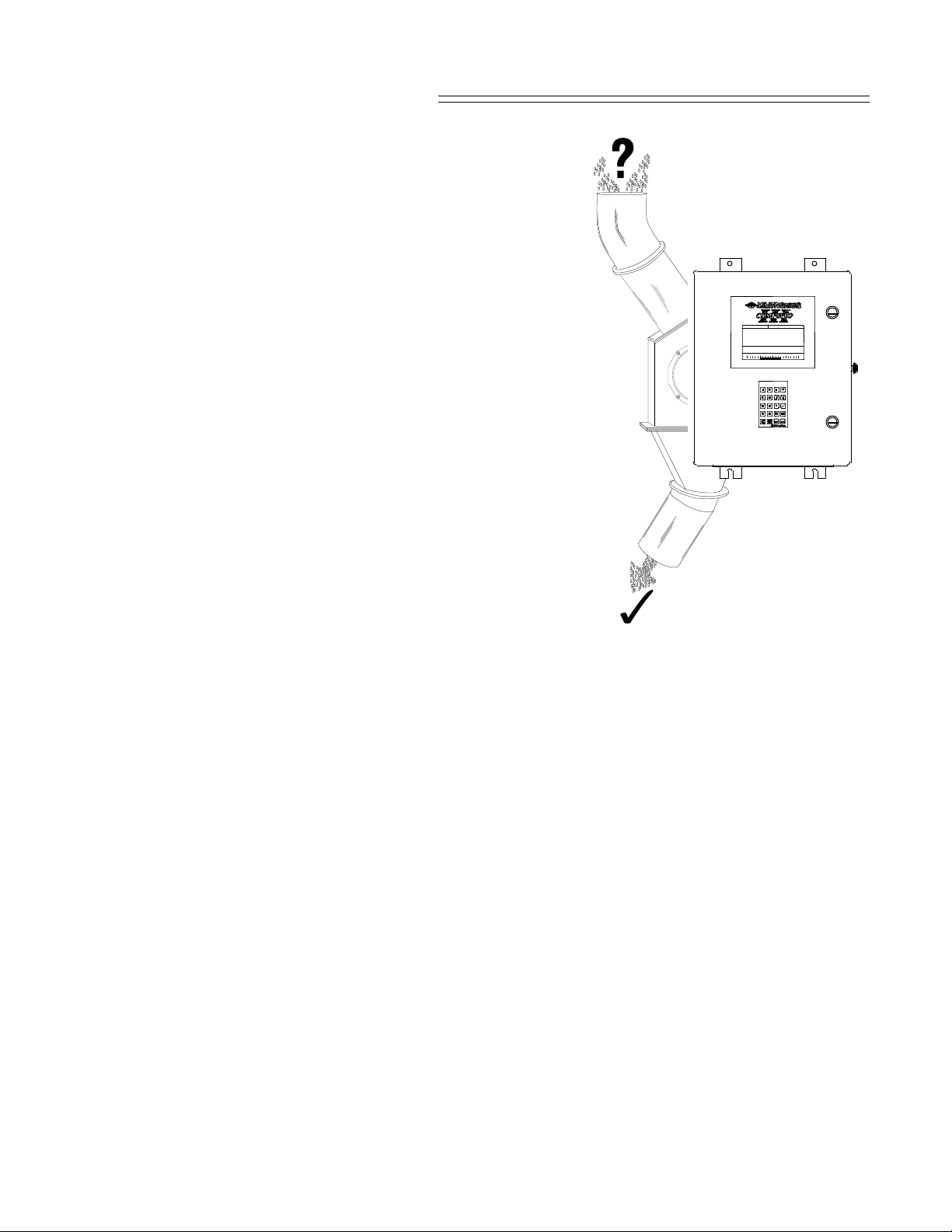
The CompuFlo III cannot be mounted in an area classed as hazardous. Where the associated flowmeter is
mounted in a hazardous area, barrier strips must be used to isola te the CompuFlo III from the hazardous area
for intrinsic safety. Encapsulated LVDT transducing elements are also available. Contact Milltronics or your
local representative for hazardous application information.
PL-368 3 – 1
■
Page 10

Page 11

START UP
HARDWARE SET UP
UNIT I.D.
The CompuFlo III identification code factory setting is 00,
as set by SW1 contacts 1 - 4.
When more than one CompuFlo III is connected to a
host computer or PLC, the identification code of each
CompuFlo III must be set to a differ ent value.
UNIT SW 1
I. D. 1 2 3 4
00 O O O O
01 C O O O
02 O C O O
03 C C O O
04 O O C O
05 C O C O
06 O C C O
07 C C C O
SW1
UNIT I. D. #
1248
METRIC
0000
IMPERIAL
UNIT SW 1
I. D. 1 2 3 4
08 O O O C
09 C O O C
10 O C O C
11 C C O C
12 O O C C
13 C O C C
14 O C C C
15 C C C C
LOCKOUT
MAIN
TOTAL
RESET
TEST
NORMAL
O = switch contact open C = switch contact closed
UNITS OF MEASURE
Two sets of Units are available; Imperial and Metric. Leave SW1 contact 5 (SW1-5) in the open position
for Imperial, or closed for Metric units. R efer to PARAMETERS / P0 - RATE UNITS for the Rate Unit
options available.
SW1-5 must be set to the desired position b ef ore i nitial pro grammi ng is performed.
To alter the Units of Measure of a programmed CompuFlo III, set SW1-5 as desired,
then perform a Reset. Refer to Parameters / P99 Reset.
LOCKOUT
Leave SW1 contact 6 (SW1-6) in the open position for normal applications. Close SW1-6 for Lockout Mode
operation, after all programming and calibration is complete. Refer to Calibration / Calibration Alternatives.
TOTALIZER RESET
Leave SW1 contact 7 (SW1-7) in the open position for normal operation. When this contact is closed, the
Main Total Display cannot be reset.
TEST MODE
Leave SW1 contact 8 (SW1-8) in the open position for normal operation. The closed position is reserved for
Milltronics service personnel.
PL-368 4 – 1
Page 12

ALTERNATE
TB2 BAUD
000
4
X
4
2
PRINTER
REMOTE
TERMINAL
SERIAL
TEST /
ADJUST
SW2
3
0
1
X
ENGLISH
SPARE
PORT 2 BAUD RATE
The CompuFlo III TB2 com munication port baud rate is independent of the PORT 1 baud rate, and is set by
SW2 contacts 1 and 2. Set the baud as required by the device connected. The factory setting is 300 baud.
Baud SW2
Rat e 1 2
300 O O
O = switch contact open
1200 C O
2400 O C
C = switch contact closed
9600 C C
NORMAL
LANGUAGE
Leave SW2 contact 3 (SW2-3) in the open position for English, or closed for alternate language, CompuFlo III
displays.
REMOTE DISPLAY
Leave SW2 contact 6 (SW2-6) open for normal operation. If a remote mounted terminal is used, SW2-6 of the
remote terminal (only) must be closed.
PORT 2 COMMUNICATION MODE
Leave SW2 contact 7 (SW2-7) open for normal operation, or closed if a serial printer is connected to PORT 2.
TEST/ADJUST MODE
Leave SW2 contact 8 (SW2-8) in the ope n position for normal operation. In th e closed position, a test menu is
displayed.
When the keypad test is selected, a pictorial representat ion of the keypad is displayed. As each keypad
button is depressed, the display indicates successful operation.
When the display contrast adjustment is selected, pressing "4" increases, and pressing "8" decreases the
display contrast.
PL-368 4 – 2
Page 13

PRE START UP CHECKS
After the Compu Flo III has been properly installed and interconnected, the following checks should be
performed prior to connecting power:
»all cable connections are correct and secure.
»the proper voltage has been selected (J1 on the mother board).
»SW1 and SW2 have been set as required.
»the POWER switch is in the OFF position.
Connect power to TB1 -51,52 and ground to TB1-50 of the CompuFlo III. Ensure all connections are secure.
Do not operate the CompuFlo III with the
ground (earth) wire disconnected.
INITIAL START UP
Se t the Co mpuFl o III POWER switch to the ON position. The CompuFlo III will enter the following
initialization routine:
COMPUSCALE/FLO III (REV DATE) (EPROM 2 REV)
TEST : (MESSAGES)
PL-368 4 – 3
Page 14
When the display initializa tion routine is complete, the display revert s to the last operati ng mode accessed. If
the CompuFlo III is not programmed, the paramet er entry display is accessed.
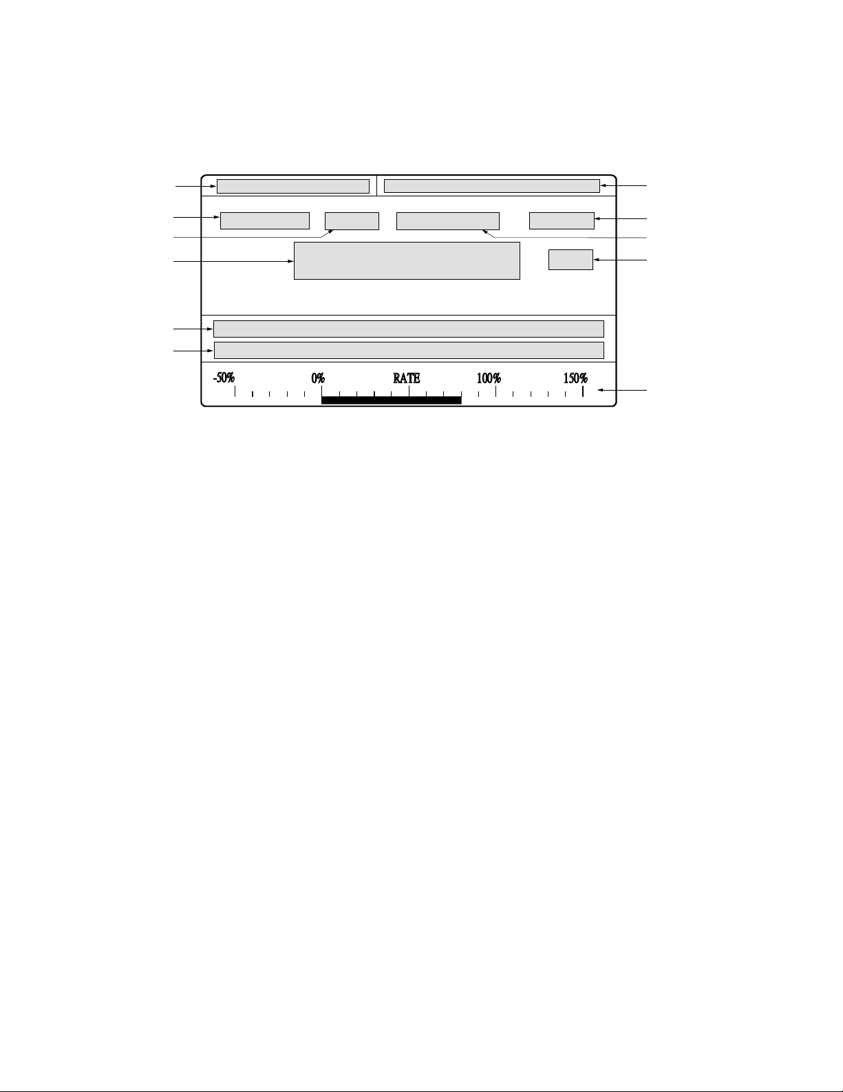
The CompuFlo III display is divided into the following fields:
MULTISPAN
FEATURE
ECAL
VALUE
RELAY
CALIB
CYCLE
UNITS
AUX 1
AUX 2
-50%
150%100%RAT E0%
RATE BAR
GRAPH
FIELD DESCRIPTION
MULTISPAN current span calibration selected. If Multispan 0 is selected, the field is blank.
RELAY current relay status (run mode). If re lays are not used, or in non-alarm, the field is blank.
FEATURE para meter number (parameter entry), calibration type (calibrate mod e), Rate or Total (run mod e)
ECAL indicates ECAL (simulated rate signal) is on. If ECAL is off, the field is blank.
CYCLE full cycles remaining before calibration completion (calibrate mode).
CALIB calibrate mode indicator. When displayed, tota lizers are on HOLD (unless otherwise specified).
VALUE the current va lue associated with the featur e selected.
UNITS the units of measure associated with the value displayed
AUX 1 parameter name (parameter entry), auxiliary message (cali b rate mode), not used (run mode).
AUX 2 parameter value range (paramet er entry) , addit ional information or error message (any mode).
BAR GRA PH represents current rate, displayed as percent of span (run mode).
PL-368 4 – 4
■
Page 15

PROGRAMMING
GENERAL
Information specific to a particular application is entered into the Com puFlo III memory, via the keypad, prior
to the calibration procedure.
KEYPAD
Button Operation Function
–
0
9
parameter entry numeric entries
4
8
RUN
PAR
ZERO
SPAN
ALT
DISP
RESET
TOTAL
parameter entry increase: analog mA output (P17 and P18 only), ECAL value (P22 only)
parameter entry decrease: analog mA output (P17 and P18 only), ECAL value (P22 only)
parameter entry decimal point
parameter entry negative entry or display prev ious parameter
any mode enter the run mode, return to previously selected display
any mode access parameter for entry or viewing
any mode access zero calibration, view current zero count
any mode access span calibration, view current span count
any mode enter the run mode, select rate or total display
any mode reset displayed totalizer value to zero (refer to Start Up\Hardware
Set Up\Total izer Reset)
CLEAR
parameter entry clear entry
calibrate mode abort calibration
ENTER
parameter entry display parameter value, or store altered parameter value,
or display next parameter
calibrate mode activate zero or span calibration, or accept calibration results
any mode with total displayed, switch to alternate total (ma in or sub)
PL-368 5 – 1
Page 16
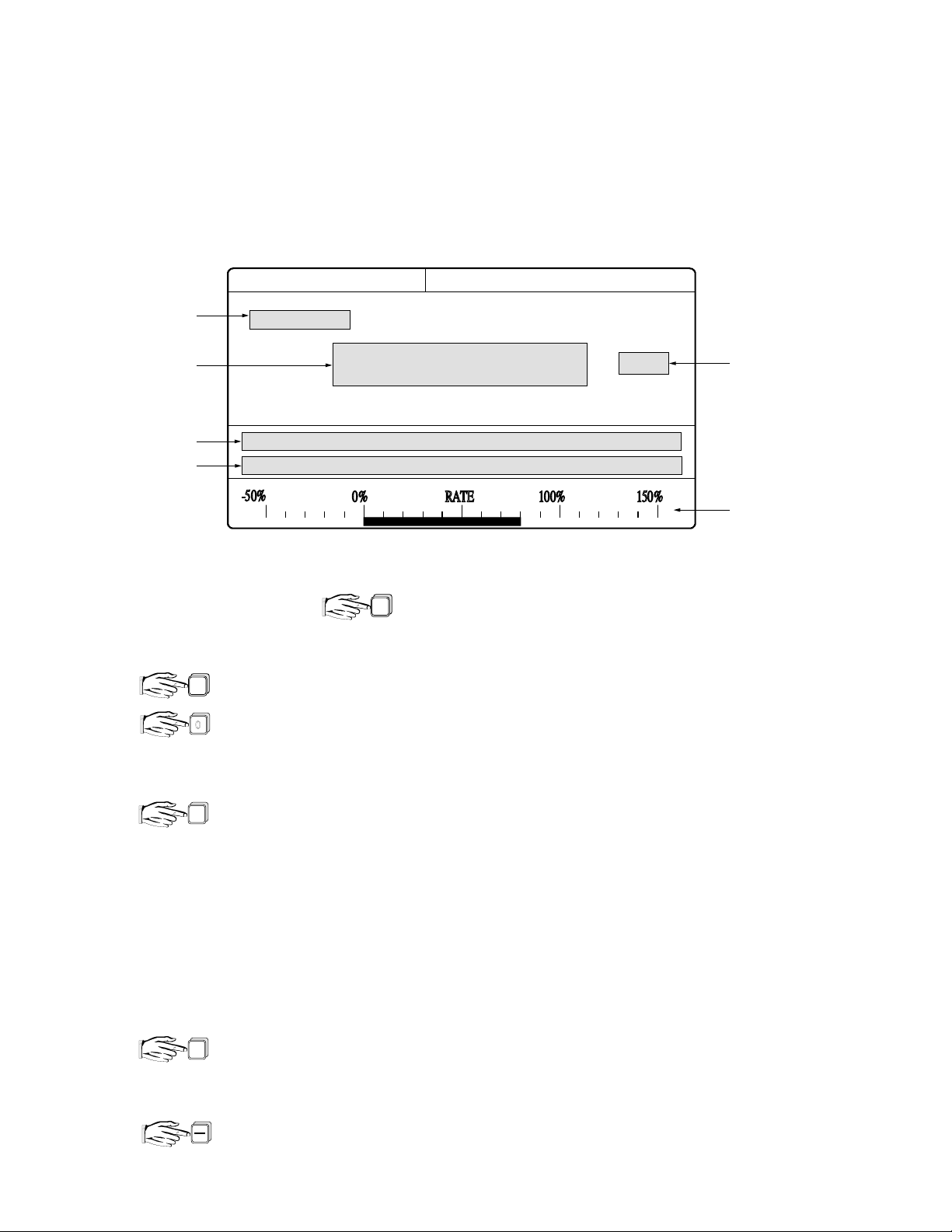
PARAMETER ENTRY
Application information must be entered into the appropriate CompuFlo III memory locations . These locations
are identified by a Paramet er Number (P#). The information entered is referred to as a Parameter Value
(Value ). To enter informat ion, the operator accesses the desired parameter number, v iews the parameter
value displayed, and then accepts or alters the current parameter value.
Common Parameter Entry Display Fields
FEATURE
VALUE
UNITS
AUX 1
AUX 2
-50%
150%100%RATE0%
RATE BAR
GRAPH
DIRECT PARAMETER ACCESS
To directly access any parameter, followed by the parameter number.
PAR
Only valid parameter numbers will be accepted. Refer to PARAMETERS for the list of valid parameter
numbers.
eg. [PARAMETER ] is displayed in the F EAT URE field, if PARAMETER 0 is desired
[PARAMETER 0 ] is displayed in the F EAT UR E field,
PAR
0
[RATE UNITS ] is displayed in the AUX 1 field.
To view the current paramet er value and auxiliary messages for the displayed parameter,
ENTER
[PARAMETER 0 ] is displayed in the FEAT UR E field
[ 1 ] is displayed in the VAL UE field (unless previously altered)
[RATE UNITS ] is displayed in the AUX 1 field
[1:T/h;2: LT/h;3: lb/ h;4: lb/m in ] is displayed in the AUX 2 field (with SW1-5 open)
AUTOMATIC PARAMETER ACCESS
Upon accessing any parameter value, pressing "ENTER" will autom atically access the next parameter in the
programming sequence. Pressing "-" will automat ically access the previous parameter.
eg. with the VA LUE field of PARA METER 0 displayed...
ENTER
[PARAMETER 1 ] is displayed in the FEAT UR E field
[ 0.0000 ] is displayed in the VAL UE field (unless previously altered)
[RATE ] is displayed in the AUX 1 field
[ENTER VALUE ] is displayed in the AUX 2 field
all fields associated with PARAMETER 0 are displayed
PL-368 5 – 2
Page 17

ALTERING PARAMETER VALUES
Once the desired parameter number is accessed, the parameter value may be accept ed or altered as
required.
eg. if the VALUE f ield of PARAMETER 0 is 1 (T/h), however 2 (LT/h) is desired
2
ENTER
[ 2 ] is displayed in the VALUE fi eld
the new value (2) is now stored in memory
LAST PARAMETER RECALL
From the Calibrate or Run mode, the last parameter accessed in the Program mode, may be recalled.
the last parameter accessed is displayed.
ENTER
PAR
PARAMETER RESET
To reset all parameters to factory settings, refer to PARAMETE RS/P99 M aster Reset.
PROGRAMMING SEQUENCE
Typically, the CompuFlo III is programmed as follows:
a) Referring to PARAMETERS, copy the selected parameter v alues to the spaces provided on
the PROGRAMMING CHART fold out.
b) Perform a MASTER RESET (P99).
c) Access each parameter ( in sequence from P 0) and enter the parameter values
from the PROG RAMM ING CHA RT.
d) Perform a Zero and Span calibration (refer to CALIBRATION)
e) Perform Span Adjust (P8) or Factoring (P9) procedures, as req uired.
Remember to copy any parameter value alterations onto
the PROGRAMMING CHART for future refer ence.
QUICK START PROCEDURE
The Quick Start Procedure describes the minimum star t up, programming, and calibration requirements of the
CompuFlo III, to obta in successful RUN mode operation for most applications.
If desired, refer to APPENDICES /Quick Start. Parameters which are not included in the procedure may be
program med after the RU N mode is entered.
■
PL-368 5 – 3
Page 18

Page 19

CALIBRATION
GENERAL
As mater ial flow characteristics often vary, frequent calibration may be required to maintain calibration
accuracy. Normally, a Zero calibration is performed first, follo wed by a Span calibration.
When the CompuFlo III is first commissioned, several Zero and Span calibrations are normally performed to
verify the calibration results are repeatable.
A Zero or Span calibration (in progress) may be aborted by .
MULTISPAN
FEATURE
ECAL
VALUE
AUX 1
AUX 2
-50%
CLEAR
CALIB
CYCLE
UNITS
150%100%RATE0%
RATE BAR
GRAPH
INITIAL CALIBRATION REFERENCES
The first calibration performed, establishes the Initial Zero and In itial Span calibration references. Subsequent
Zero and Span calibration results are compared to these references. The maximum acceptable deviation
between an Initial Calibration Reference and a subsequent calibration result is 12.0% of span. Otherwise,
[ZERO OUT OF RANGE] or [SPAN OUT OF RANGE] is displayed in the AUX 2 field.
While a calibration in progress is establishing an initial calibration reference, the dynamic count value is
displayed in the VALUE field. Otherwise, the dynamic rate value is displayed.
The initial calibration refer ences may be reset. Refer to Parameters/P77 Initial Zero Reset and P88 Initial
Span Reset. Both initial calibration refer ences (along with other programming) are erased by a Master Reset
(P99).
PL-368 6 – 1
Page 20

ZERO
The average no flow input from the flowmeter is calculated and stored in memory as a Zero count. With no
material flow or Test Weight applied to the flowmeter...
[ZERO] is displayed in the FEATURE field. The current Zero counts are displayed in the
ZERO
VALUE field. [ENTER: CALIBRATE MODE] is displayed in the AUX 2 field.
to initiate the calibration. [CALIB] is displayed in the CALIB field and [ZERO IN PROGRESS]
ENTER
is displayed in the AUX 2 field. The time required to complete the calibration (and calibration
accuracy) is dependent upon the Calibration Duration (Refer to Parameter s/P30 Calibration
Duration). The number of full calibration cycles remaining until completion, is displayed in
the CYCLE field.
When complete, the deviation from the last Zero calibration is displayed in the VALUE field,
as a percent of span.
to accept the new calibration. Otherwise, investigate the reason for the deviation and
ENTER
perform the Zero calibration again.
SPAN
The simulated material flow provided by the Test Weight (or number of Test Weights) is calculated and stor ed
in memory as a Span count. (Ref er to Alternate Test Ref erences, if a Test Weight is not us ed.)
With no material flow or Test Weight applied to the flowmeter.. .
[SPAN] is displayed in the FEATURE field. The current S pan counts are displayed in the
SPAN
VALUE field.
With [CALIB] displayed in the CALIB field, apply the Test Weight to the flowmeter
(as described in the flowmeter manual).
If [ CALIB] is not displayed, respond to the CompuFlo III display prompts until this
indicator is obtained, before applying the Test Weight.
to initiate the calibration. The time required to complete the calibration (and calibration
ENTER
accuracy) is dependent upon the Calibration Duration (Refer to Parameter s/P30 Calibration
Duration). The number of full calibration cycles remaining until completion,
is displayed in the CYCLE field.
When complete, the deviation from the last Span calibration, is displayed in the VAL UE field,
as a percent of span.
to accept the new calibration. Otherwise, investigate the reason for the deviation
ENTER
and perform the Span calibration again.
CALIBRATION ACCURACY
With the Initial Zero and Initial Span calibration complete, RUN mode operation is possible, however greater
calibration accuracy may be requ ired. The Test Reference value (P7) is an approximation, based on typical
material flowrate characteristics.
To adjust the Span calibrat ion to suit the actual material flow characteristics encountered, perf orm a m aterial
test. (Refer to Par ameters/P8 Span Adjust). The Test Reference value is automatically adjusted so the Test
Weight will accurately simulate material flow during future Span calibrations.
The CompuFlo III is now ready to be put into servi ce, (refer to Operation).
PL-368 6 – 2
Page 21

CALIBRATION ALTERNATIVES
AUTO ZERO
This feature automatically performs a Zero calibration, whenever material flow ceases in the RUN mode.
If the Auto Zero feature is desired, provide a dry contact input to the CompuFlo III terminals TB1-34 and
TB1-37. The contact may be activated by a material feed controlling device such as a motor control, material
control gate, or valve. The contact must be closed when the material feed is stopped.
When the contact is closed, and material flow has stopped (within 4% of span from the current zero refer ence)
[AUTO ZERO IN PROGRESS] is displayed in the AUX 2 field. The time required for completion is dependent
upon Calibration Duration (P30). The number of fu ll calibration cycles remaining until completion is displayed
in the CYCLE field.
When complete, the Auto Zero is compared to the last operator Zero.
If the Auto Zero is within 2% of span from the last operator zero, the CompuFlo III briefly displays
[CALIBRATION COMP LETE] in the AUX 2 field and the deviation from the current zero refer ence in the
VALUE field. The Auto Zero is automatically accepted and RUN mode operation continues.
Otherwise, the Auto Zero results are rejected, and operation continues with the previous zero reference.
LOCKOU T MODE
In this mode, parameters may be accessed for viewing. However, if a parameter value alteration is attempted,
the alteration is not permitted and [CERTIFICATION LOC KOUT] is displayed in the AUX 2 field.
To activate the lockout mode, close SW1 contact 6 (SW1-6) after the CompuFlo III is programmed
and calibrated.
The maximum acceptable deviation between the last Zero performed by the operator (before closing this
contact) and any subsequent Zero, is limited to 2% of span. Span calibrations are not permitted in this mode.
ON-LINE SPAN CALIBRATION
The On-Line Calibration feature may be used to routinely check (and adjust if necessary) the Span calibration
in the RUN mode, without interrupting the material flow.
Install a weigh bin (bin or silo equipped to provide a 4-20 mA output proport ional to weight) preceding the
flowmeter material infeed. Connect the weigh bin out put to the CompuFlo III TB1-18,19 terminals. Install a
material feed control device, preceding the weigh bin.
feeder
Max. (e.g. 90%)
High (e.g. 80%)
Calibrate the CompuFlo III for the weigh bin 4-20 mA input (P27).
Access On-Line Parameter Selection (P28) to enter the weigh bin:
reference weight , max limit, high limit, and low limit setp oints.
Assign a relay to the On-Line Calibration function, P51=2 (Relay 1)
or P52 =2 (Relay 2). Connect the assigned relay contacts to the
weigh bin material feed control device, such that when the On-Line
reference weight
relay is energized, the weigh bin material feed is stopped.
Low (e.g. 30 %)
When the On-Line Calibration is activated (P29) , normal operat ion
continues until the weigh bin fills to the max limit (e.g. 90%). While
filling, the percent full is displayed in the VALUE field. When the
max limit is reached, the relay assigned the On-Line function,
material flow
energizes to stop the weigh bin material feed.
PL-368 6 – 3
Page 22

As material is discharged from the weigh bin, the On-Line tota lizer is automatically activated when the high
limit (e.g 80%) is reached. When the low limit (e.g. 30%) is reached, the tota lizer is de-activated and the
assigned re lay de-energizes, thereby enabling the material feed to the weigh bin.
The CompuFlo III On-Line material total is compared to the weight of material discharged from the weigh bin
between the h igh and low limits (reference weight). The deviation between these values is displayed as a
percent of span in the VALUE field. The On-Line calibration r esults may be accepted, or rejected.
ALTERNATE TEST REFERENCES
For most applications, a Test Weight is applied to the flowmeter, to simulate material flow for the Span
calibration. Alternatively, the Co mpuFl o III internal refer ence (ECAL), may be used to simulate a flowmeter
input for Span calibrations. ECAL is normally used when applying a Test Weight would be impractical or
inconvenie n t (especially when t he flowmeter is installed in a hazardous area).
When a Test Weight is used exclusively, Test Reference selection (P20) is not required.
When the ECAL reference is selected (P20=1), ECAL is automatically applied when a Span calibration or
Factoring (P9) is activated, and removed when the process is complete or aborted. If a Test Weight and
ECAL are used periodically , the appropriate Test Reference must be selected (P20) before a Span calibration
(or Factoring) is performed.
When the ECAL reference is on, [E CAL] is displayed in the ECAL field.
ECAL CALIBRATION (INITIAL REFERENCE)
With essential parameters (P0, P1,P2,P3,P7, and P21) programmed as required, select the ECAL T est
Reference (P20=1). Access P7 again, [PARAMETER 7E] is displayed. (The "E" indicates the P7 value
displayed is associated with the ECAL Test Reference.)
Perform a Zero and Span calibration. (A Test Weight is not required as ECAL is automatically applied for
Span calibrations when P20=1). To obtain an accurate ECAL/flowmeter signal corre lation, perf orm a ma terial
test. Refer to Parameters/ P8 Span Adjust.
Upon the comp letion of the material test, the new ECAL Test Reference (P7E) value is automatically adjusted
so ECAL will accurately simulate material flow during future Span calibrations.
For best re sults, if the new P7E value is not between 50% to 100% of the Design Rate (P1) value, perform an
ECAL Adjust. Refer t o Parameters/ P22 ECAL Adjust.
ECAL CALIBRATION (ALTERNATE REFERENCE)
After the CompuFlo III Span calibration is completed with a Test Weight, ECAL may be used for subsequent
Span calibration checks. Using ECAL as a secondary reference is especially useful, when frequent Span
calibration checks are required but using a Test Weight would be impractical.
Select the ECAL Test Reference (P20=1). Adjust ECAL to the value desired (P22=2). Factor the adjusted
ECAL reference to the current span (P22=2 or P9).
After a primary reference (typi cally Test Weight) Span calibra tion deviation is
accepted, Factor the secondary reference (typical ly ECAL) to the new span.
Remember to select the appropriate Test Reference (P20) before
performing a Span calibration or Factoring procedure.
PL-368 6 – 4
■
Page 23

PARAMETERS
GENERAL
(F) indicates the paramet er value factor y setting (where applicable)
(V) indicates the parameter value ma y be viewed only.
(E) indicates the parameter value is essential for basic operation.
PARAMETERS
P0 RATE UNITS ( E)
Defines the desired Rate display engineering units of measure.
With SW1, contact 5 (SW1-5) in the open position (Imperia l units):
enter: 1 = short tons per hour (F)(T/h) 1 T/h = 2000 lb/h
2 = long tons per hour(LT/h) 1 LT/h = 2240 lb/h
3 = pounds per hour(lb/h)
4 = pounds per minute(lb/h)
With (SW1-5) in the closed position ( Metric units):
enter: 1 = metric tonnes per hour (F)(t/h) 1 t/h = 1000 kg/h
2 = kilograms per hour(kg/h)
3 = kilograms per minute(kg/m)
The SW1-5 position and the value of P0 should be set before any other programming.
To alter the Rate Units of a programmed CompuFlo III, set SW1-5 as desired, perform a
Reset (refer to Parameters / P99 Reset) and set P0 to the desired value.
P1 RATE (E)
Defines the rate of m ater ial flow (in P0 units) which will produce the full scale Rate output. (F=0.0000)
enter: Design Rate, Range = 0.0001 to 99999
P2 LOCAL TOTAL (E)
Defines the amount of m aterial to be tota lized, prior to initiating an internal totalizer (and Main / Sub Tota l
display) update, (F = 1). The weight portion of the Rat e Unit (P0) is assumed.
enter: .0001 .001 .01 .1 1 10 100 1000
.0002 .002 .02 .2 2 20 200 2000
.0005 .005 .05 .5 5 50 500 5000
If [TOT AL REGIS TRA TION TOO LOW] is displayed, enter a higher value.
PL-368 7 – 1
94/04/14
Page 24

P3 REMOTE TOTAL (E)
Defines the amount of material tota lized, prior to ini tiating a remote totali zer relay contact closure, (F = 1). The
weight portion of the Rate Unit (P0) is assumed.
The frequency of remote totalizer contact closures is dependent upon t he material flowrate and the Remote
Total value. When a remote totalizer is connected to TB1-48,49, refer to the totalizer manufacturers
instructions to determine the maximum pulse frequency. Lower values increase and higher values decrease
the relay contact closure frequency.
enter: .0001 .001 .01 .1 1 10 100 1000
.0002 .002 .02 .2 2 20 200 2000
.0005 .005 .05 .5 5 50 500 5000
If [TOTAL REGISTRATION TOO LOW] is displayed, enter a higher value.
P7 TEST REFERENCE (Test Rate) (E)
Defines the simulated material flowrat e represented by the Test Reference selecte d (P20) for the Mu lti Span
(P26) selected.
This value is entered in design Rate (P0) units. If a value of 0 is entered, the system design Rate (P1)
value is assumed.
enter: Test Rate (refer to the associated flowmeter instruction manual for
calculation instructions. F = 0 until P1 is set.)
P8 SPAN ADJUST
Adjusts the test reference calibration results to improve material flowrate measurement accuracy.
% CHANGE - Calculate the deviation between the CompuFlo III Tota l and the actual material weight.
A positive value reduces (negative increases) the Rate displayed.
% Span Error = CompuFlo III Total - Actual Material Weight x 100
Actual Material Weight
MATERIAL TEST - Alternatively, the automatic method may be used. Perform a material test as follows:
a) With no material flow and the test reference (Test We ight, or ECAL) removed,
b) Sele ct the ma terial test option, select the HOLD TOTAL or ADD TO TOTAL option
press "ENTER" to activate the Material Test.
c) Feed a sample of material through the flowmet er press "ENTER" to stop the Material Test.
d) Enter the actual material sample weight. The Span deviation % is displayed.
e) Press "ENTER" to complete, (or "CLEAR" to abort ), the procedure.
Span Adjust calibrations are improved with larger material samples. Run at the normal flowrate; which should
exceed 50% of the design Rate (P1).
A Span Adjust, utilizing either method, alters the span count of the Multispan number (P26) selected, and
Test Reference (P7) value of the Test Reference selecte d (P-20). Copy the altered P7 value to the
Programm ing Chart
enter: 0 = Span Adjust not required (F)
1 = % change, (enter desired adjustment as a percent of span)
2 = material test, (ent er the actu al material weight )
PL-368 7 – 2
Page 25

P9 FACTORING
Adjusts the Test Reference value (P7) of the Test Reference selected (P20).
After the CompuFlo III is calibrated utilizing a known Test Reference (e.g. Test Weight representing 20 T/h),
the material flowrate represented by an unknown Test Reference (e.g. alternate Test Weight), may be
established.
This featur e may also be used if Span calibrations per formed with one Test Reference, tend to consistently
provide greater accuracy than Span calibrations with another Test Reference.
Factoring is not necessarily required after a Span Adjust (P8), as the T est Reference (P7) value of the Test
Reference (P20) for the Multispan Number (P26) selected , is automatically factored by the CompuFlo III.
After performing a Span calibration utilizing the known Test Reference (P20):
a) With the material flow stopped, apply the unknown Test Refer ence.
b) Select the Test Reference to be adjusted (P20).
c) press "1","ENTER" and wait for the Calibration Duration (P30) . When complete,
d) copy the adjusted Test Reference (P7) value displ ayed, to the PR OGRAMMING CHART.
If [ZERO CALIBRATION REQUIRED] is displayed, perform a Zero calibration
prior to re - attempting the factoring procedure. If a Zero calibration has
been performed very recently, press "CLEAR","ENTER", and proceed.
enter: 0 = Factoring not required (F)
1 = Factoring required (with material flow stopped, and s e lecte d test reference a ppli ed)
P10 L OW TOTAL CUTOFF
Defines the minimum material flowrate to be processed for Local Total values and Remote Total contact
closures. Range = 0.0 to 100.0.
This feature eliminates the totalizer activity which could occur due to flowmeter vibration or small amounts of
air passing through the flowmeter, when material flow is stopped.
With calibration complete, material flow stopped, and the Rate displayed, observe the highest display value.
Enter the value as a percent of design Rate (P1).
A value of 0 will permit the Total display to count up or down. Remote Total contact closures cease while the
total counts down. The contact closures will resum e when the Total display regains the amount by which it
counted down.
enter: desired value (F = 3.0)
PL-368 7 – 3
Page 26

P11 RATE DISPLAY DAMPING
Defines the level of damping to be applied to the Rate display. Range = 1 to 999
This may be used to stabilize a fluctuating rate display without affecting accuracy. Higher values provide more
stabilization. Press "RUN" to instantly update the Rat e display to the curr ent rate.
enter: desired value (F = 1)
P14 RATE OUTPUT DAMPING
Defines the level of damping to be applied to the Rate O utput. Range = 1 to 999
This may be used to stabilize a fluctuating Rate Output without affecting accuracy. Higher values provide
more stabilization. Rate Output Damping is disabled if the Rate Output Average (P15) feature is utilized.
Press "RUN" to instantly update the Rat e Output to the current rate.
enter: desired value (F = 1)
P15 RATE OUTPUT AVERAGE
Defines the period in seconds between Rate O utput updates. The value held, corresponds to the averaged
Rate of the previous period. Range = 0 to 999.
A value of 0 may be entered if Rate output averaging is not desired.
enter: desired value (F = 0)
P16 RATE BAR GRAPH ASSIGNMENT
Defines the output value the Rate Bar Graph Display represents, as a percent of span.
enter: 0 = Rate Output (P14) (F)
1 = undamped Rate
2 = Rate Display (P11)
P17 RATE OUTPUT MIN
Adjusts the Rate Output reference value for minimum material flowrat e. Range = 0 to 4095.
a) With Change Mode activate d and mA meter in series with the load connected to TB1-20,21,
b) Press "CLEAR" before keying in the estimated reference value, and pressing "ENTER".
c) Repeat step b) as required to produce the desired minimum Rate Output.
Briefly press "4" (increase by 10’s), or "8" (decrease by 1’s) to fine adjust the reference value, if necessary.
ent er: 0 = no adjust ment required
1 = Activat e Change Mode (F = 631, for 4.00 mA)
PL-368 7 – 4
Page 27

P18 RATE OUTPUT MAX
Adjusts the Rate Output refer ence value for maximum material flowrate. Range = 0 to 4095.
a) With Change Mode activated and mA meter in series with the load connected to TB1-20,21,
b) Press "CLEAR" before keying in the estimated reference value, and pressing "ENTER".
c) Repeat step b) as required to produce the desired maximum Rate Output.
Briefly press "4" (increase by 10’s), or "8" (decrease by 1’s) to fine adjust the reference va lue, if necessary.
ent er: 0 = no adjust ment required
1 = Activate Change Mode (F = 3160, for 20.00 mA)
P20 TEST REFERENCE SELECTION
Defines the type of test reference selected to represent a material flowrate.
The test reference selected is indicated when the following parameters are accessed:
OPTION DESCRIPTIO N TEST REFERENCE (P7) SPAN ADJUST (P8) FACTORING P9
0 Test Weight [PARAMET ER 7] [PARAMETER 8] [PARAMETER 9]
1 ECAL [PARAMETER 7E] [PARAMETER 8E] [PARAMETER 9E]
When P20 = 1, ECAL is automatically applied whenever a Span calibration or Factoring procedure is
activated, and removed when the procedure is complete. Refer to Calibration \ Alternate Test References for
ECAL span calibration instructions.
ent er: 0 = rate (F)( test w eight)
1 = ECAL (electronic reference)
P21 SENSOR TYPE
Defines the type and number of flowmeter transducing elements utilized.
enter: 0 = LVDT (linear variable differential transformer), (F)
1 = 1 load cell
2 = 2 load cells
PL-368 7 – 5
Page 28

P22 ECAL ADJUST
Applies and permit s the adjustment of the internal electronic test reference.
Refer to Calibration / Alternate Test References for ECAL Span calibration instructions.
ECAL Adjust cannot be accessed unless the ECAL Test Reference (P20) is selected.
ECAL is adjusted in t he R UN mode with no material flow or Test Weight appli ed to the
flowmeter. When the Adjust option is selected, t he simulated flowmet er input is
applied to the CompuFlo III . Record all totalizer values before and after ad just ing EC AL.
To adjust ECAL :
a) Enter the RUN mode before accessing P22 and selecting the adjust option.
b) Press "CLEAR" before keying in the estimated reference value, (range = 0 to 4095)
and pressing "ENTER". If Span calibration already exists, entering 0 automat ically adjusts
ECAL to 100% of the current span.
c) Repeat step b) as required while observing the Rate Bar Graph.
d) Briefly press "4" (increase by 10’s) or "8" (decrease by 1’s) to fine adjust the reference
value, if necessary.
e) When the Rate Ba r Graph indicates the desired simulated Rate, press "ENTER"
f) Press "ENTER" again to Factor ECAL to the current span and comple te the adjustment.
enter : 0 = ECAL off, (if P20 = 1, ECAL will automatically be applied when a Span calibration or
Factoring process is activat ed, and removed when the proc ess is complete.
1 = ECAL on, (ECAL will be held on except while a Zero calibration is in progress.)
2 = ECAL adjust (adjust as desired, F=2000 when P21=0, 200 when P21=1 or 2).
P25 LINEARIZER
Provides compensation for repeatable non-linear material flow characteristics.
If the material flowrate through the flowmeter is relatively constant during normal operation (except for a few
moments during start up and shut down) linearization should not be requi red.
In rare cases, electron ic linearization may be required if the process monitored demands high accuracy over a
wide range of flowrates.
If the flowmeter linearity seems to vary (beyond acceptable limits) at various material flowrates:
1) Perform a new Zero and Span calibration (as close as possible
to 100% of P1 Rate) and a Span Adjust (P8).
2) Apply various Test Weights to the flowmeter to verify mechanical linearity, Non-linear operation with
Test Weights indicates a mechanical flowmeter problem. Investgate and correct.
3) Referring to the associated flowmeter manual(s), ensure all fl owmeter application recommendations
were followed. (If possible, modify the feeder or chute work as recommended).
PL-368 7 – 6
Page 29

If operation still seems to be non-linear, perform the following tests at 25%, 50%, and 75% of the P1 Rate.
a) With material flow stopped, reset the Sub Total.
b) Run a batch of material (larger is bett er) thr o ugh the flowmeter, maintaining a constant flowrate.
c) Record the batch Sub Total
d) Weigh the material batch (if the actual batch weight is not already known).
If for every flowrate tested, the actual batch wei ght is equal (or within the accuracy requirements) to the
displayed Sub Total, the act ual flowrate to measured flowrate relationship is linear.
Otherwise, enter the % comp en sation required for each flowrate (automatically selected).
% Compensation = Actu al Batch Weight - Sub Tota l x 100
Sub Tota l
Turn th e linearizer on, and repeat steps a) to d). Adjust the Point 1, 2, and 3 flow rates and % compensation
values as required until the desired results are obtained.
The linearizer values are applied to any Multispan (P26) selected.
enter: 0 = off
1 = on
2 = adjust, enter: point 1 flowrate (F=25% of (P1) Rate)
point 1 adjustment (F=0%)
point 2 flowrate (F=50% of (P1) Rate)
point 2 adjustment (F=0%)
point 3 flowrate (F=75% of (P1) Rate)
point 3 adjustment (F=0%)
P26 MULTISPAN
Defines the Span calibration result to be used for subsequent measurements. Range = 0 to 8.
This feature may be used to store the Span calibratio n associated with a number of different materia l types,
flow characteristics, particle sizes, etc.
To perform a Span calibration for a specific operating condition:
a) Select the Multispan number to be associated with the current operating condition.
b) Enter the Test Reference value (P7) for the Test Reference to be used (P20).
c) Perform a Zero and Span calibration.
d) Perform a Span Adjust (P8) or Factoring (P9), as required.
To recall the c alibration result (when the associated operating condition is re-encountered), select the
appropriate Multispan number. The Mu ltispan number may be selected by providing one or more temporary or
permanent closed contact(s) between the TB1 COM (e.g. TB1-37) and the following TB1 terminals:
PL-368 7 – 7
Page 30

MULTISPAN TB1 TERMINALS CONNECTED TO COM
NUMBER 41 40 39 38
1OOOC
2OOCO
3OOCC
4OCOO
5OCOC
6OCCO
7OCCC
8COOO
O = contact open C= contact closed
For convenience, the Multispan number selection may be provided by a BCD switch connected to the
appropriate TB1-38,39,40,41, and COM contacts.
Alternatively, the Multispan number may be selected via the keypad. If "0" is entered, the MULTISPAN field of
the display is blank and Multispan 1 is utilized.
enter: desired value, (TB1-38,39,40, and 41 contacts must be open), (F = 0).
P27 ON-LINE: INPUT CALIBRATION
Calibrates the CompuFlo III for the Zero and Span mA input from the b in weighing system. These values
represent the empty and full weight of the On-line calibration weigh bin. Range = 0.000 to 25.00
enter: 0 = On-line calibration not required (F)
1 = Zero calibration (with weigh bin empty, press "ENTER" when the display value is stable.)
2 = Span calibration (with weigh bin full, press "ENTER" when the display value is stable.)
P28 ON-LINE: PARAMETER SELECTION
Defines the actual material weights associated with the On-line calibr ation.
The reference weight is the actual weight of material contained in the wei gh bin between the high and low
limits. Enter the reference weight value in the weight portion of the Rate Units (P0) selected. Enter the max,
high, and low limits as a percent of full weigh bin :
Refer to Calibration / On-Line Span Calibration for comp lete calibration instruct ions.
enter : reference weight, range = 0.000 to 99999 (F = 0)
max limit, (material weight required to stop mater ial feed). Range = 0.000 to 100.0, (F = 0)
high limit, (material weight required to activate totalizer). Range = 0.000 to 100.0 (F = 0)
low limit, (material weight required to de-activate total izer). Range = 0.000 to 100.0 (F = 0)
PL-368 7 – 8
93/12/01
Page 31

P29 ON-LINE CALIBRATION
Activ a tes the On-line calibration.
Upon completion, the On-line calibration may be accepted, or rejected. Refer to Calibration / On-Line Span
Calibration for complete instruct ions.
enter: 0 = On-Line calibration not required (F)
1 = Act ivate On-L ine calibration
P30 CALIBRATION DURATION
Defines the number of 10 second time periods the CompuFlo III will utilize to perform a Zero or Span
calibration, Factoring (P9) , or Verification Totalizer (P31) operation.
Range = 0.01 to 99
A low value reduces calibration time, while a high value increases calibration accuracy.
ent er: desired value, (F = 1)
P31 VERIFICATION TOTALIZER
Activates a secondary internal totalizer which totals the amount of material conveyed during the Calibration
Duration (P30). This feature may be used to verify calibration accuracy from the RUN mode without stopping
material flow.
The amount of material totalized by the verification totalizer may be included or excluded from the
totalizer counts.
enter: 0 = verification totalizer off (F)
1 = do not totalize material during the verif icat ion.
2 = totalize material during the verification.
P32 VERIFICATION TOTALIZER RESOLUTION
Defines the amount of m aterial weight to be measured, prior to initiating a verification tot alizer update. The
weight portion of the Rate Unit (P0) is assu med.
enter: 0 = same as the Local Total (P2) value.(F)
1 = 1/10 of the Local Total (P2) value.
PL-368 7 – 9
Page 32

P40 BAUD RATE
Defines the baud rate for PORT 1 data message communication.
The baud r ate must be set to the value required by t he externa l dev ice(s) connected to the PORT1 (T B1)
current loop or RS-232C communication connections.
enter: 300
1200
2400
9600 (F)
P41 DATA TRANSMIT INTERVAL
Defines the time lapse in minutes between unsolicited data message transmissions.
Range = 0 to 99999
The Data Transm it Interval may be adjusted as re quired to control the level of message traffic between the
CompuFlo III and the external device(s) connected to the PORT 1 and/or PORT 2 bipola r current loop or
RS-232C communication connections.
If a value gr eater than 50,000 is enter ed, the data message (P42) is transmitted only when the TB1-35,37
contacts are closed.
enter: desired value, (F = 30)
P42 DATA MESSAGE
Defines the ASCII message to be transmitted after every Data Transmit Interval (P41) or when TB1- 35,37
contacts are closed.
The current tim e and date ar e transmitt e d with each messa ge. The SYSTEM message includes the value of
parameters P0, 1,2,3, 7, and 21.
enter: 0 = no message (F)
1 = RATE
2 = MAIN TOTAL
5 = RATE and MAIN TOTAL
9 = SYSTEM
P43 SERIAL PRINTER
Sets the communication mode to suit a serial printer.
enter: 0 = off (F)
1 = on (SW2-7 must be closed for PORT 2/printer communication)
PL-368 7 – 10
Page 33

P51 RELAY 1
Defines the operation of Relay 1 as a Rate Alarm or On-Line calibration prefeed control.
If the Rate Alarm function is selected, the High Limit, Low Limit, and Deadband values are entered as a
percent of span.
The High Limit is the high alarm set p o int value which will cause the re lay to de-en ergize. If a high limit is not
required, set the high limit to 0.
The Low Limit is the low alarm set point value which will cause the re lay to de-energize. If a low limit is not
required, set the low limit to 0.
The Deadband is the amount which the dynam ic Rate must exceed the low limit and/or fall below the high
limit before the re lay energizes. The deadband value must be less than the difference between the high and
low limit setpoints.
If the On-line calibration function is selected, the Max Li mit and Low Limit values are set by On-line:
Parameter Selection (P28). When the Max Limit setpoint value is reached the relay energizes and remains
energized until the Low Limit setpoint value is reached.
ent er: 0 = Relay 1 off (F) (always de-energized)
1 = RATE
2 = ON-LINE
If the Rate function was select ed, the High Limit may now be set.
enter: desired High Limit value, (Range = 0.000 to 100.0, F = 98), advances to Low Limit
desired Low Limit value, (Range = 0.000 to 100.0, F = 35), advances to Deadband
desired Deadband value, (Range = 0.000 to 100.0, F = 5)
P52 RELAY 2
Defines the operation of Relay 2 as a Rate Alarm or On-Line calibration prefeed control.
If the Rate Alarm function is selected, the High Limit, Low Limit, and Deadband values must be enter ed as a
percent of span.
The High Limit is the high alarm set p o int value which will cause the re lay to de-en ergize. If a high limit is not
required, set the high limit to 0.
The Low Limit is the low alarm set point value which will cause the re lay to de-energize. If a low limit is not
required, set the low limit to 0.
The Deadband is the amount which the dy namic va lue must exceed the low limit and/or fall below the high
limit before the re lay energizes. The deadband value must be less than the difference between the high and
low limit setpoints.
If the On-line calibration function is selected, the Max Li mit and Low Limit values are set by On-line:
Parameter Selection (P28). When the Max Limit setpoint value is reached the relay energizes and remains
energized until the Low Limit setpoint value is reached.
ent er: 0 = Relay 1 off (F) (always de-energized)
1 = RATE
2 = ON-LINE
PL-368 7 – 11
Page 34

If the Rate function was selected, the High Limit may now be set.
enter: desired High Limit value, (Range = 0. 000 t o 100.0, F = 98), advances to Low Limit
desired Low Limit value, (Range = 0.000 to 100.0, F = 35), advances to Deadband
desired Deadband value, (Range = 0.000 t o 100.0, F = 5)
P55 100% TEST REFERENCE (V)
Displays the design Rate (P1) value.
P60 SOFTWARE REVISION (V)
Displays the revision number of the software progr am stored in EPROM 1.
P61 MEMORY TEST (V)
Perform s a test on th e EPROM 1 memory. U pon completion, [CHECKSUM CORRECT] is displayed to
indicate a successful test.
P63 TOTALIZER CONTACT DURATION
Defines the duration of the remote totalizer relay contact closure in seconds. Range = 0.025 to 8.323
This value is automatically set, based on the Rate (P1) and Remote Total (P3) values entered. If necessary,
adjust this value to provide the duration required by the device connected to TB1-51,52. An entered value is
automatically adjusted to the next higher value permitt ed.
If t he value entered is too high, [TOT AL REGISTRATI ON TOO LOW] will be displayed. Incre ase the Remote
Total (P3) value.
When 0 is entered, the system selected value is entered.
enter: desired value (F = 1, until P1 and P3 values are entered)
P64 ZERO RECORD (V)
Displays the number of operator initiated Zero calibrations perf ormed since the last Master Reset (P99) or
Initial Zero Reset. (F = 0).
P65 SPAN RECORD (V)
Displays the number of operator initiated Span calibrations performed since the last Master Reset (P99) or
Initial Span Reset (P88). (F = 0).
PL-368 7 – 12
Page 35

P66 SECURITY LEVEL
Defines the level of operator access permitted.
This feature may be utilized to ensure the programming and/or calibration is not inadvertentl y altered. Access
to all RUN mode displays and the P66 value is permitted at all Security levels. When a security level is
selected, Security is not invoked until the RUN mode is enter ed. From th e RUN mode, accessing P66
disables Security until the RUN mode is entered again.
enter: 0 = fu ll access permitted (F)
1 = parameter values secured
2 = parameter and Main Total display values secured.
3 = parameter values, Zero and Span calibrations secured.
4 = parameter and Main Total display values, Zero and Span calibrations secured.
P70 CLOCK/CALENDAR
Defines the current Time and Date, to be ma inta ined by the internal clock.
enter: desired value, (Hours, range = 0 to 23, advances to minut es),
desired value, (Minutes, range = 0 to 59, advances to day),
desired value, (Day, range = 1 to 31, advances to month),
desired value, (Month, range = 1 to 12, advances to year),
desired value, (Year, range = 00 to 99, r eturns to hours)
P71 TIME (V)
Displays time in t wenty-f our hour format, (HH:MM).
P72 DATE (V)
Displays date in YY/MM/DD format.
P77 INITIAL ZERO RESET
Performs a Zero Calibration to estab lish the new Initial Zero count value.
This feature is normally used in response to the [ZERO OUT OF RANGE ] message, when the cause of the
deviation is not otherwise correctable. This condition could occur as the result of an intended change in the
Design Parameter values or a mechanical change to the flowmeter assembly.
enter: 0 = not required (F)
1 = Initial Zero Reset
P80 V/F CONVE RTER OUTP UT (V)
Displays a reference count propo rtional to the input level from the flowmeter. Range = 0 to 131,000.
This feature is normally used to verify the integrity of the flowmeter load sensors and cable(s).
PL-368 7 – 13
Page 36

P81 LOAD CELL A (V)
Displays the input from the load cell connected to TB1-1,2 in mV. Range = 0.00 to 50.00
Access to this parameter may on ly be gained when SENSOR TYPE (P21) is set to 2. This feature is normally
used to verify the integrit y of th e load cell after initial installation or subsequent replacement.
P82 LOAD CELL B (V)
Displays the input from the load cell connected to TB1-3,4 in mV. Range = 0.00 to 50.00
Access to this parameter is gained when SENSOR TYPE (P21) is set to any value greater than 0. This
feature is normally used to verify t he integrity of the load cell after initial installation or subsequent
replacement.
P85 V/F CONVERTER INPUT (V)
Displays the sum of the amplified load sensor (P21) input voltage(s). Range = -1.00 to 4.00.
P86 ON-LINE CALIBRATION (Input Current) (V)
Displays the CompuFlo III TB1-18,19 mA input from the bin weighing system. Range = 0.00 to 25.00.
P88 INITIAL SPAN RESET
Performs a Span calibration to establish a new Initial Span count value.
This feature is norm ally used in response to the [SPAN OUT OF RANGE] message, when the cause of the
deviation is not otherwise correct able. This condition could occur as the result of an intended change in the
Design Parameter values or a mechanical change to the flowmeter assembly.
enter: 0 = not required (F)
1 = Initial Span Reset
P90 BALANCING PROCEDURE
Initiates the Load Cell Balancing procedure.
This procedure is only required if the connected flowmeter util izes two load cell sensing elements and is
equipped with two Test Weight suspension points. This parameter may on ly be accessed when Sensor Type
is set for 2 load cells (P21 = 2).
Prior to initial calibration or fo llowing a load cell replacement, the load cell balancing procedure should be
performed. When the flowmeter load cell signals are balanced, variable material flow patterns have less effect
on flowmeter measurements.
When the load cell balancing procedure is initiated, P91 through P95 must be accessed in sequence. Direct
access to these parameters is not permitted.
PL-368 7 – 14
Page 37

When the loadcell balancing procedure is completed, perform a Zero and Span calibraton before entering the
Run mode.
enter: 0 = load cell balancing not required (F)
1 = balancing procedure required, (press "1", "ENTER" to advance to P91)
P91 POS B LC (A+B) (V)
Displays the summed load cell input counts.
Apply the Test Weight to a flowmeter Test Weight suspension point. (Refer to the flowmeter instruction
manual for Test Weight application instructions).
enter: the displayed value (when stable) to advance to P92.
P92 POS B LC (B) (V)
Displays the load cell input counts of one load cell.
Ensure the Test Weight (as applied for P91) is not moved or otherwise disturbed.
enter: the displayed value to advance to P93.
P93 POS A LC (B) (V)
Displays the load cell input counts of one load cell.
Move the Test Weigh t to the other flowmeter Test Weight suspension point.
enter: the displayed value (when stable) to advance to P94.
P94 POS A LC (A+B) (V)
Displays the summed load cell input counts.
Ensure the Test Weight (as applied for P93) is not moved or otherwise disturbed.
enter: the displayed value to advance to P95.
P95 LOAD CELL BALANCE (V)
Displays the count value, which when entered, will ba lance the load cell signals.
enter: the displayed value to complete the load cell balance.
PL-368 7 – 15
Page 38

P99 RESET
Initiates a memory reset.
This feature clears memory locations and restores paramet er values to their original factory sett ings. The
implementation of a Reset necessitates CompuFlo III reprogramming and recalibration.
Neither Reset Level affects the Clock/Calendar settings. A Partial Reset maintains the previous, P17, P18,
P20, P21, P22, P27, P40, P41, P42, P43 and load cell balanc ing settings.
enter: 0 = reset not required (F)
1 = Partial Reset
9 = Master Reset
P100 PARAMETER LIST (V)
Displays paramet er names in groups of 10. Pr essing "ENTER" advances the display to the next group. This
parameter is not automatically scrolled and therefore must be accessed directly.
PL-368 7 – 16
■
Page 39

PROGRAMMING CHART
PAR NAME VALUE VALID RANGE (F or _ = factory setting)
P0 RATE UNITS [ ] IMP: 1(T/h), 2(LT/h), 3(lb/ h),4(lb/min) Metric: 1(t/h),2(kg/h),3(kg/min)
P1 RATE [ ] 0.0001 to 99999 (F = 0.000)
P2 LOCAL TOTAL [ ] 1,2,or 5 x .0001 .001,.01,.1,1,10,100,or 1000
P3 REMOTE TOTAL [ ] 1,2,or 5 x .0001 .001,.01,.1,1,10,100,or 1000
P7 TEST REFERENCE [ ] 0.0001 to 99999 (F = 0)
P8 SPAN ADJUST [ ] 0 (off), 1 (%change), 2 (material test)
P9 FACTORING [ ] 0 (off ), 1(fa ctor test refer ence)
P10 LOW TOTAL CUTOFF [ ] 0.0 to 100.0 (F=3.00)
P11 RATE DISPLAY DAMPING [ ] 1 to 999
P14 RATE OUTPUT DAMPING [ ] 1 to 999
P15 RATE OUTPUT AVERAGE [ ] 0 to 99999
P16 RATE BAR GRAPH ASSIG NMENT [ ] 0 (Rate Output, P14), 1 (undamped Rate), 2 (Rate Display, P11)
P17 RATE OUTPUT MIN [ ] 0 to 4095 (F = 631)
P18 RATE OUTPUT MAX [ ] 0 to 4095 (F = 3160)
P20 TEST REFERENCE SELECT [ ] 0 (test weight), 1 (ECAL)
P21 SENSOR TYPE [ ] 0 (LVDT), 1 ( 1 load cell), 2 (2 load cells)
P22 ECAL ADJUST [ ] 0 (off), 1 (on), 2 (adjust ), [ ] count
P25 LINEARIZER [ ] 0 (off), 1 (on), 2 (adjust)
[ ](pt 1),[ ](pt 2),[ ](pt 3) RATE
[ ](pt 1),[ ](pt 2),[ ](pt 3) % COMP
P26 MULTISPAN [ ] 0 to 8 (F = 0)
P27 ON-LINE:INPUT CALIB. [ ] 0 (off), 1 (zero), 2 (span)
P28 ON-LINE:PARAMETER SELECT [ ] (ref weight)[ ],(max) [ ],(hi)[ ], (lo)[ ]
P29 ON-LINE CALIBR ATI O N [ ] 0 (off), 1 (activate)
P30 CALIBRATION DURATION [ ] 0.1 to 99 (F = 1)
P31 VERIFICATION TOTAL [ ] 0 (off), 1 (HOLD TOTAL), 2 (add to Total)
P32 VERIFICATION TOTAL RES [ ] 0 (same as P2) , 1 (P2 x 1/ 10)
P40 B AUD RATE [ ] 300, 1200, 2400, 9600
P41 DATA TRANSMIT INTERVAL [ ] 0 to 99999 (F = 30)
P42 DATA MESSAGE [ ]
P43 SERIAL PRINTE R [ ] 0 (off), 1 (on)
P51 RELAY 1 [ ] 0 (off), 1 (Rate), 2 (On-line)
P52 RELAY 2 [ ] 0 (off), 1 (Rate), 2 (On-line)
P55 100% TEST REFERENCE [ ] 0.0001 to 99999 (F = Rate (P1), display only)
P60 SOFTWARE REVISION [ ] 1.00 to 99.99 (display only)
P61 MEMORY TEST [ ] Pass or F ail, (display only)
P63 TOTALIZER CONTACT DUR [ ] 0.025 to 8.323 seconds (F = 1 until P1 and P3 are set)
P64 ZERO RECORD [ ] (display only)
P65 SPAN RECORD [ ] ( d isplay only)
P66 SECURITY LEVEL SELECT [ ] 0(off),1(P#’s),2(P#’s,Total),3(P#’s,Zero,Span),4(P#’s,Total,Zero,Span)
P70 CLOCK/CALENDAR [ ] hrs(0-23),min(0-59),day(1-31),month(1-12),year(00-99)
P71 TIME [ ] HH:MM display, (24 hour format)
P72 DATE [ ] YY/ MM/DD format
P77 INITIAL ZERO RESET [ ] 0 (off), 1 (reset)
P80 V/F CONVERTER OUTPU T [ ] 0 to 131,000 counts, (display only)
P81 LOAD CELL A INPUT [ ] 0.00 to 50.00 mV, (display only)
P82 LOAD CELL B INPUT [ ] 0.00 to 50.00 mV, (display only)
P85 V/F CONVERTER INPUT [ ] -1.00 to 4.00 V, (display only)
P86 ONLINE: MA INPUT [ ] 0 to 25.0 mA, (display only)
P88 INITIAL SPAN RESE T [ ] 0 (off), 1 (reset)
P99 RESET [ ] 0 (off), 1 (Partial ), 9 (Master)
P100 PARAMETER LIST [ ] 0 to 99 in groups of 10, (display only)
0 (off), 1 (Rate),2 (Total),5 (Rate and Total),9 (System)
[ ](hi),[ ](lo),[ ] (deadband) in %
[ ](hi),[ ](lo),[ ] (deadband) in %
PL-368 8 – 1
Page 40

Page 41

OPERATION
INITIAL OPER ATION
Prior to the initial operation of the CompuFlo III the following checks should be made:
» the test ref erence should be removed from the flowmeter.
» the totalizer(s) should be reset to zero.
The CompuFlo III is now ready for service.
Ensure the CompuFlo III is in the RUN mode.
To enter the RUN mode,
RUN
The CompuFlo III assumes the last RUN mode display accessed.
ALT
If necessary, to display Ra te.
Open the material prefeed, ensuring the design Rate is not exceeded.
ALT
to display the current material tota l. Observe the total value incrementing.
DISP
DISP
A program of calibration checks should be performed frequently at first . The frequency of these checks may
be reduced as time and experience dictate.
All personnel should be inst ruct ed on the safe and proper operation of the CompuFlo III and be instructed
when and if a calibration check should be performed, what level of zero and span deviation is acceptable, and
when to reset the totalizer(s).
If desired, a photocopy of the following page may be provided, to personnel responsible for CompuFlo III
daily operation.
PL-368 9 – 1
Page 42

NORMAL OPERATION
START UP
Ensure power is supplied to the CompuFlo III.
When power is first applied, the CompuFlo III will automatically perfor m a series of tests for about 10 seconds
and then resume operation in the last mode entered.
The following procedures may be perf ormed on a routine basis, as required. Access to the Zero and Span
calibration, and Reset Total functions may be restrict ed.
ZERO CALIBRATION CHECK
Ensure the flowmeter test reference (Test Weight or ECAL) is removed. With no material flow,
ZERO
ENTER
to initiate a zero calibration. When complete (time dependent on programming) the
deviation from the last operator initiated zero calibration is displayed.
ENTER
if the zero deviation is acceptable.
If the zero deviation is not acceptable, or if [ZERO OUT OF RANGE] is displayed, investigate the reason for
the deviation, correct the condition, and try the zero calibration again.
SPAN CALIBRATION CHECK
If the following features were implemented during system programming, perform the following checks:
FEATURE CHECK
Test Reference Select (P20) Ensur e the desired Test Reference is selected.
Mu ltispan Number (P26) Ensure the appropriate Multispan number is selected.
Apply the flowmeter test reference (Test Weight or ECAL). With no material flow,
SPAN
ENTER
to initiate a span calibration. When complete (time dependent on programming) the
deviation from the last operator initiated span calibration is displayed.
ENTER
if the span deviation is acceptable.
If the span deviation is not acceptable, or if [SPAN OUT OF RANGE] is displayed, investigate the rea son f or
the deviation, correct the condition, and try the span calibration again.
Remove the flowmeter test reference.
RESET TOTAL
If necessary, reset the CompuFlo III tota lizer.
RESET
TOTAL
ENTER
CLEAR
to initiate a total izer reset.
to select the Main o r Sub Total.
to reset the selected Total display value to 0.
Refer to the manufacturers instructions to reset the remote to ta lizer , if any.
RU N
RUN
(and then if necessary) to display Rate.
ALT
DISP
Ac tiva te the material prefeed control device (if any) to begin running material through the flowmeter.
ALT
DISP
since the last Total Reset.
to access the Total displa y, observe the amount of material run through the flowmeter
PL-368 9 – 2
■
Page 43

COMMUNICATION
GENERAL
The CompuFlo III may be operated in one of the following serial communication modes:
» Remote (Milltronics Terminal)
» Host (IBM PC compatible computer or PLC)
» Serial Printer
The Bipolar Current Loop may be utilized for cable runs up to 1500 metres (5000 ft). If communication with an
RS-232 device is required, the Milltronics BIC-II or CVCC may be used to convert the Bipolar Current Loop to
RS-232. The BIC-II is also capable of Bipolar Current Loop to RS-422 conversion.
The CompuFlo III RS-232 port may be connected directly to an RS-232 device, where the communication
cable run is less than 15 m (50 ft).
To set the Port 1 communication baud rate to suit the device connected, refer to PARAMETERS/P40. To set
the Port 2 baud rate, refer to START UP/Hardware Set Up.
CompuFlo III
CVCC
or BIC II
( if required )
serial
printer
remote
terminal
OR
customer’s computer*
(*remote terminal emulation
software available)
( or BIC II )
customer’s
computer
PL-368 10 – 1
CVCC
Page 44

REMOTE COMMUNICATION
This mode provides complete access to all CompuFlo III functions via a Milltronics remote terminal. To
receive communication from the CompuFlo III PORT 1 or PORT 2 connection, SW2-6 of the remote terminal
must be closed.
Alternatively, a remote terminal emulation software package is available for IBM PC compatible computers
supporting colour graphics (VGA).
If the computer (supporting a parallel printer) is connected to PORT 1, (when P43=1) a printout containing the
Data Message (P42) selected is initiated each time:
» the Data Transmit Interval (P41) lapses
» a dry contact is provided across CompuFlo III TB1-35 and COM (e.g. TB1-36).
HOST COMMUNICATION
Host communication permits up to 16 CompuFlo III’s (serially connected via PORT 1), to communicate with a
computer or Programmable Logic Controller. Refer to Start Up\Hardware Set Up\Unit I.D. Code).
In this mode, data acquisition and analysis is accomplished by a customer supplied software package. Refer
to Protocol.
SERIAL PRINTER COMMUNICATION
Two modes of serial printer operation are available.
The Port 1 mode (similar to previous Milltronics integrator versions) printout is initiated each time :
» a dry contact is provided across pins 7 and 17 of the printer DP25 connector.
» the Printer Test button is pressed.
The printout contains the : time, date, total, and total engineering units.
The Port 2 mode is compatible with any serial printer.
Close the CompuFlo III SW2 contact 7 (SW2-7) and set the Data Transmit Interval (P41), Data Message
(P42) and Serial Printer (P43) parameters as desired. Refer to Parameters.
The printout, containing the Data Message selected, is initiated each time :
» a dry contact is provided across the CompuFlo III TB1-35 and COM (e.g. TB1-36)
» the Data Transmit Interval elapses.
PL-368 10 – 2
Page 45

PROTOCOL
Protocol refers to the format, sequence and value of the data fields utilized in Host Mode communication
messages. Each data field of a CompuFlo III message contains one or more bytes of ASCII binary code.
Each byte contains:
» 8 data bits
» no parity bit
» 1 stop bit
DATA FIELD DESCRIPTIONS
The following data fields are utilized in CompuFlo III host mode messages.
somIdentifies the start of a message (STX), ASCII character = 02.
DEVICE
Identifies the CompuFlo III to which the message applies. The device number equals the Unit
I.D. code, as set by SW1 contacts 1 - 4. ASCII characters = 00 to 15.
+20 mA
0
-20 mA
s12345678s
tsnrtttttt
at ddhhhhho
rp
t
MTIdentifies the message type transmitted, ASCII characters:
50 = material flow rate
53 = totalized material
READING
Contains the measurement value in the units of measure selected during CompuFlo III
programming. The number of bytes in this data field will vary dependent upon the reading
value. Up to 8 ASCII characters including the decimal point may be transmitted.
UNITS
Three ASCII characters identify the totalizer engineering units (MT = 53 only). The first
character is always a space. The remaining characters may be:
t = Metric Tons
LT = Long Tons
T = Short Tons
kg = Kilograms
lb = Pounds
EOM
Identifies the end of a message (CR), ASCII character = 0D.
PL-368 10 – 3
Page 46

MESSAGE REQUESTS
Message requests must be transmitted from the host to the CompuFlo III in the following format.
som DEVICE MT eom
Example:
Data ASCII Example
Field Character Description
som 02 start of message
DEVICE 01 for CompuFlo III # 1
MT 50 material flow rate request
eom 0D end of message
MESSAGE RESPONSES
The CompuFlo III response to a flow rate (MT=50) message request will be in the following format.
som DEVICE MT READING eom
Example:
Data ASCII Example
Field Character Description
som 02 start of message
DEVICE 00 from CompuFlo III# 0
MT 50 material flow rate response
READING 392.5 is 392.5
eom 0D end of message
The response to a material total (MT=53) message request will be in the following format.
som DEVICE MT READING UNITS eom
Example:
Data ASCII Example
Field Character Description
som 02 start of message
DEVICE 00 from CompuFlo III# 0
MT 53 material total response
READING 129.2 is 129.2
UNITS MT Metric Tonnes
eom CR end of message
PL-368 10 – 4
■
Page 47

ALPHABETICAL PARAMETER LISTING
PARAMETER PARAMETER PARAMETER PARAMETER
NAME NUMBER NAME NUMBER
Balancing Procedure P90 Parameter L ist P100
Baud Rate P40 Rate Bar Graph Assignment P16
Calibration Duration P30 Rate P1
Clock/Calendar P70 Rate Output Average P15
Converter Input (V/F) P83 Rate Output Max P18
Converter Output (V/F) P80 Rate Out put M in P17
Damping, Rate Display P11 Rate Units P0
Damping, Rate Output P14 Record, Zero P64
Data Transmit Interval P41 Record, Span P65
Data Message P42 Relay 1 P51
Date P72 Relay 2 P52
ECAL Ad just P22 Security P66
Factoring P9 Sensor Type P21
Initial Zero Reset P77 Serial Printer P43
Initial Span Reset P88 Software Revision P60
Linearizer P25 Span Adjust P8
Load Cell Balance P95 Test, Memory P61
Load Cell Input , A P81 Test Reference P7
Load Cell Input , B P82 Test Reference 100% P55
Master Reset P99 Test Reference Selection P20
Multispan P26 Time P71
On-line: Calibration P29 Total Contact Duration P63
On-line: Calibration mA P86 Total, Local P2
On-line: Input C alibration P27 Total, Low Cutoff P10
On-line: Parameter Selection P28 Total, Remote P3
POS A LC (A+B) P94 Total, Verification P31
POS A LC (B) P93 Total, Verification Resolution P32
POS B LC (A+B) P91
POS B LC (B) P92
PL-368 11 – 1
Page 48

MAINTENANCE AND SPARE PARTS
MAINTENANCE
The CompuFlo III requires no maintenance. However a program of periodic preventative ma intenance should
be initiated. This should include regular inspection, general cleaning and good housekeeping practices.
Enclosures and printed circuit boards should be cleaned only when the power is disconnected at the main
breaker. The use of a vacuum cleaner to remove foreign material dislodged with a clean dry paint brush is
recommended. Check all electrical connections for signs of corrosion and/or electrical arcing.
The CompuFlo III memory backup and calibrator batteri es should be replaced annually. The 3.6 Volt lithium
battery (located on the mother board top right corner) should only be re placed while the CompuFlo III power is
ON. The 9 Volt calibrator battery is located on the back of the CompuFlo III door.
SPARE PARTS
The following list de scribes t he CompuFlo III components which may be ordered as a spare part. The
ITEM # refers to the number which should be included on the purchase order to identify the part required.
DE SC R I P TION I TEM #
Bat tery, Lithium, 3.6 V, AA, (Memory) 20200031
Battery, A lkaline , 9 Volt, (Calibrator) 20200025
Enclosure Bottom Plate 24650116
Fuse, 0.75A, 250V, Slo-B lo, CSA, (Main) 22550112
For Remote Terminal ordering informat ion, contact Milltronics or your distributor.
PL-368 11 – 2
Page 49

ERROR MESSAGES
The following messages may be encountered during CompuFlo III programming, c alibration, or operation.
DISPLAY MESSAGE DESCRIPTION
[ABORTED] The activated process or procedure was not completed correctly
(or before "CLEAR" was pressed). Retry the feature att empted.
[AUTO ZERO ABORTED] The Auto Zero was more than 2% of span from the last operator
Zero before SW1-6 was closed. Refer to Calibration/Lockout Mode.
[AUTO ZERO LIMIT EXCEEDED] The Auto Zero was more than 2% of span from the last operator
Zero. Refer to Calibration/Auto Zero.
[CALIBRATION ABORTED] "CLEAR" was pressed before the activated calibration was accepted.
[CERTIFICATION LOCKOUT] Attempted access to a function which is r estr icte d during operation
in the Lockout mode. Refer to Start up/Hardware Set Up/Lockout.
[CHECKSUM ERROR] Integrator f ailed Memory Test. Refer to Parameters/ P61 Memory Test.
[ENTRY ERROR] Invalid parameter selection or alteration. Refer to Parameters.
[PARAMETERS NOT ENTERED] A calibration or run mode operation was attempted before essential
parameter va lues were entered. Refer to Parameters/P1,P2,P3, and P7.
[REMOTE TOT AL SATURATION] The syst ems totalization capabilities were exceeded; the Remote Total
counts are incorrect. Refer to [TOTAL REGISTRATION TOO LOW].
[SECURITY LOCKOUT] Attempted access to a function which is restricte d by Security
(P66). Refer to Parameters/P66 Security.
[SPAN CALIB REQUIRED] Attempted RUN mode operation prior to accepting an Initial
Span calibration. Refer to Calibration/Span.
[SPAN ERROR] The attempted calibration (or adjustment) would have exceeded
the systems span capabilities. Investigate and correct before retr y ing.
[SPAN O UT OF RANGE] The attempt ed Span was greater than 12% of span from the Initial
Span. Refer to Paramet ers/P88 In itial Span Reset.
[TEST REFERENCE VALUE REQUIRED] A Test Reference value (P7) has not been entered for the current
Test Reference selected (P20). Refer to Parameters.
[TOTAL REGISTRATION TOO LOW] The value entered exceeds totalization capabilities Refer to
Paramet ers/P2 Local Total, P3 Remote Tota l & P63 Contact Dur ation.
[ZERO CALIB REQUIRED] Attempted RUN mode operation or Span calibration prior to
accepting an initial Zero calibration. Refer to Calibration/Zero.
[ZERO CALIB REQUIRED] Span calibration or Factor ing (P9) procedure attem pted from
[OR PRESS CLEAR] the RUN mode. Press "CLEAR" only if a Zero has been
performed recently.
[ZERO OUT OF RANGE ] The attempt ed Zero calibration was greater than 12% span from
the Initial Zero reference. Refer to Parameters/P77 Initial Zero Reset.
PL-368 11 – 3
Page 50

TROUBLE SHOOTING
Every CompuFlo III integrator is subjected to extensive quality assurance procedures to ensure the highest
possible degree of quality, reliability, and performance is achieved.
The following listing indicates the probable cause, and proper course of action to be taken should
the specified fa ult symptom occur.
SYMPTOM CAUSE ACTION
Display blank »Loss of power »check power wiring, jumpers, and fuse
»check POWER switch is ON
»check AC supply
»check daughter board HD2-1,4
Will not complete a Zero or Span » Loss of input signal(s) » check P80
calibration » check sensor wiring
» Wrong Design Parameter » check programming value(s)
Calibra tion takes too long » Calibration Duration too long » reduce P30 value
Zero calibration deviation drifts » Loose mechanical assembly » tighten all bolts and clamps
» Sensing head not level » refer to flowmeter manual
Span calibration deviation drifts » Loose mechanical assembly » tighten all bolts and clamps
» Variable material flow patt erns » refer to flowmeter and
application guideline manuals
Accuracy is not within » Test Reference doesn’t » perform a new Zero and Span limits
desired limits represent true operating calibration, followed by a
conditions Span Adjust (P8).
» Calibration Duration too short » increase P30 value *
» On-Line Calibration required » Refer to Calibration.
* Perform a new Zero and Span calibration and a Span Adjust (P8), after the recommended action.
For more trouble shooting information, refer to the flowmeter and application guideline instruction manuals.
PL-368 11 – 4
Page 51

QUICK START
START UP
Flip the POWER switch to ON. The Comp uFlo III will perform a self test for 10 seconds.
MASTER RESET - Prepares the CompuFlo III for initial programming or complete reprogramming.
Proceed to OPERATION if previous programming and calibration is to be retained.
PAR
9 9
ENTER
9
ENTER
[PARAMETE R 99 ] Master Reset parameter accessed.
[PARAMETER ] is displayed after 10 seconds.
RATE UNITS - Defines the desired Rate display units of measure.
• [PARAMETER 0 ] Rate Units parameter accessed.
PAR
ENTER
0
with SW1-5* open with SW1-5* closed
ENTER
1
2
3
4
tons/hour (T/h) for tonnes/h our (t/h)
long tons/hour (LT/h) for Kilograms/hour (kg/h)
ENTER
pounds/hour (lb/h) for Kilog rams/minute (kg/min)
ENTER
pounds/min (lb/min)
ENTER
ENTER
1
ENTER
2
ENTER
3
* Switch SW1-5 is located on the CompuFlo III mother board, (top left corner).
DESIGN RATE - Defines the material flowrate which will pr oduce the full scale Rate Output.
ENTER
[PARAMETER 1 ] Design Rate parameter accessed, key in flowrate value,
ENTER
to store the keyed in value in memory.
LOCAL TOTAL - Defines the material weight (in P0 weight units) required for each Total display update.
ENTER
[PARAMETER 2 ] Local Total parameter accessed.
Key in one of the followi ng material weight values:
0.0001, 0.001, 0.01, 0.1, 1, 10, 100, 1000
0.0002, 0.002, 0.02, 0.2, 2, 20, 200, 2000
0.0005, 0.005, 0.05, 0.5, 5, 50, 500, 5000
ENTER
to store the keyed in value in memory.
Pl-368 11 – 5
Page 52

REMOT E TOTAL - Defines the material weight required to cause a remote TOTAL relay contact closure.
ENTER
[PARAMETER 3 ] Remote T ota l parameter accessed.
Key in one of the following material weight values:
0.0001, 0.0 01, 0.01, 0.1, 1, 10, 100, 1000
0.0002, 0.0 02, 0.02, 0.2, 2, 20, 200, 2000
0.0005, 0.0 05, 0.05, 0.5, 5, 50, 500, 5000
ENTER
to store the keyed in value in memory.
TEST REFERENCE - Defines the simulated material flowrate ( in P0 units) represented by the Test Weight.
ENTER
[PARAMETER 7 ] Test Reference parameter accessed.
Key in the calculated value, (ref er to the flowmeter manual for Test Weight calculation instructions)
to store the keyed in value in memory.
ENTER
SENSOR TYPE - Identifies the type of input signal(s) from the flowmeter.
[PAR AMETER 21 ] Sensor Type parameter accessed.
PAR
2
ENTER
if an LVDT is connected, or if a single load cell is connected,
0
or if dual load cells are co nnected.
ENTER
1
ENTER
1
ENTER
2
CALIBRATION - Prepares the CompuFlo I II for operation.
If [ZERO OUT OF RANGE] or [SPAN OUT OF RANGE] is displayed after a calibration attempt, refer to the
PARAMETERS section for Initial Zero Reset (P77) and/or Initial Span Reset (P88) instructions.
ZERO
With no material flow or test weight(s) applied to the flowmeter,
ZERO
the zero count value from the last Zero calibration is displayed.
ENTER
to start the calibration, when complete the deviation from the last Zero is displayed.
ENTER
to accept the new Zero calibration results.
Pl-368 11 – 6
Page 53

SPAN
With no material flow and the test weigh t( s) applied to the flowmeter,
SPAN
the span count value from the last Span calibration is displayed.
ENTER
to start the calibration. When complete t he deviation from the last Span is displayed.
ENTER
to accept the new Span calibration results.
OPERATION
Ensure the test weight is not applied to the flowmeter before open ing the m aterial feed.
RATE & TOTAL DISPLAYS
RUN
to enter the RUN mode.
ALT
DISP
(if required) to obta in the Rate display.
ALT
to obtain the Tota l display.
DISP
(as required) to obta in the Ma in Total or Sub Total values.
ENTER
RESET TOTAL - Resets the Ma in or Sub Total value displayed.
RESET
CLEAR
TOTAL
the Main or Sub Total value displayed is now 0.
PERFORMANCE ENHANCEMENT
For optimum accuracy, perform Zero and Span calibrations frequently. Read this manual thoroughly
for details on all CompuFlo III features. A material test utili zing the Span Adjust (P8) parameter,
is recommended.
Pl-368 11 – 7
■
Page 54

Page 55

330 mm
( 13" )
178 mm
( 7" )
OUTLINE and MOUNTING
11 mm dia.
( 0.4" )
4 places
101 mm
( 4" )
enclosure bo ttom plate
( for cable / conduit entr ance )
406 mm
( 16" )
435 mm
( 17.1" )
PL-368 12 – 1
FIG. 1
Page 56

calibrator
batter y
COMPUFLO III LAYOUT
D1
R1
C1
LD1
R2
Q2
B1
CALIBRATOR IVPN 24751327-01 ML 51026351
MILLTRONICS
MADE IN CANADA
U1
D2
R3
PETERBOROUGH ONTARIO
RC1
Q1
C2
CR1
C3
calibrator
(door mount)
memor y/ clock
battery
SW 1
SW 2
display
display
board
barrier
jumpers
P8V
N8V
COM
EP ROM 1
SW1
47
PIN 1
7
SW2
P5V2
N5V2
SPAN No. (1-8):2
MAIN TOTAL
1263957
SN
EPROM 1
PIN 1
20
ML 51026331
EPROM 2
R1:RATE HI R2:RATE LO
TIME / DATE / MEMORY
1
PN 24751325-04
COM
T
3.6 VOLT
LITHIUM
BATTERY
P24V
P5V
N24V
EP ROM 2
voltage
select
jumper
main
fuse
Power
switch
V LOAD
TB2
-50%
345
1
2
345
12
+-+-
RCVXMT
CURRENT
SHLD
COMM PORT 2
LVDT
150%100%50%0%
TOTAL
230VAC
200VAC
J1
115VAC
100VAC
ON
1
4
6
OFF
NC
NO
UP
7
6
9
8
7
6
9
8
COM
RCV
XMT
RS232
ECHO
P15V
STD HAZ’DHAZ’D STD
SPEED
SENSOR
EXC FUSE
A
K
3
1
MILLTRONICS COMPUSCALE /
N15V
2
3
1/4 AMP
MDL
SLOBLO
FUSE
COMPUFLO DISPLAY DRIVER
2
2
FU2
1/4 AMP
SLOBLO
MDL
FUSE
MADE IN CANADA
PETERBOROUGH
ONTARIO
A
K
3/4 AMP
SLOBLO
MDL
FU1
FUSE
P13V
P18V
P30VI
ECAL
VOLTAGE
SELECT
POWER
CW
RATE
ACOM4
mother
board
TB1
123
+
A
6
5
4
89 1112
7
+
B
+-
-
C
LOADCELLS
+
D
13 14
10
-
++
-
-
SEN
SEN
EXCEXC
SHLD
-SIG
151617
COM
LVDT
18 19 202122
EXC
-
-+
RCV
SHLD
COMM PORT 1
28 2930313233
COMRCVXMT
EXC
RS232
23 24 252627
+-+-+-+
XMT
ONLN
RATE
CURRENT
MA
MILLTRONICS
COMPUSCALE / COMPUFLO
MADE IN CANADA
PETERBOROUGH . ONTARIO
SN
SN
PL-368 12 – 2
SPEED
COMSIG
CONST
34 35 363738
39
414243 4445464748
40
1
COM
COM
PRINT
A.ZERO
SPANS
J2
INSTRUCTION BOOK
INSTRUCTION BOOK COMPUFLO I I I PL-368
ML 51026341
842
RELAYS
SEE INSTRUCTION
BOOK FOR RELAY
RATINGS
COMPUSCALE I I I PL-367
PN 24751326-04
49 50 51
52
L1
L2
GR
N
TOTAL
POSITION J1 FOR
100/115/200/230/
VAC OPERATION
[ 50/60 HZ VA ]
65
R2R1
FIG. 2
93/12/01
Page 57

CompuFlo III
CompuFlo III
TB1
COMPUFLO III / FLOWMETER INTERCONNECTION
LVDT
TB1
SINGLE LOAD CELL
DUAL LOAD CELLS
CompuFlo III
TB1
1. Where a flowmeter must be installed in a hazardous area consult Milltronics or your
distributor for wiring instructions.
2. Where the integrator to load cell flowmeter cable exceeds 150m (500 ft):
A) remove jum pers from CompuFlo III, TB1 - 9,10 and TB1 - 11,12
B) run an additional shielded conductor to the junc tion box nearest the load cell(s) from:
» CompuFlo III TB1 - 10 to loadcell(s) red
» CompuFlo III TB1 - 11 to loadcell(s) black
FIG. 3
PL-368 12 – 3
Page 58

CompuFlo III
TB1
POWER, AUTO ZERO & RATE OUTPUT WIRING
POWER
Power
Connection
100/115/200/230
V A C 6 5 VA
Voltage
Select
AUTO ZERO
prefeed activated
dry contact
RATE OUTPUT
CompuFlo III
TB1
to mA input of device
750 Ω Max load
1. Ensure the CompuFlo III J1 position matches the power to be applied to TB1 - 51,52.
2. The Auto Zero contact must be closed when the material feed is stopped,
if Auto Zer o calibration is desired.
PL-368 12 – 4
FIG. 4
Page 59

RELAY WIRING
ALARM / CONTROL RELAYS
CompuFlo III
TB1
AC TOTALIZER DC TOTALIZER
CompuScale III
CompuFlo III
TB1
TB1
to alar m / control devices
REMOTE TOTALIZER RELAY
CompuScale III
48 49
CompuFlo III
TB1
TB1
Relay contacts are shown in
de-energized condition.
(Power OFF and Alarm Status)
48 49
R1 C1
R2
C2
AC
* POWER
SOURCE
Shaded area recommended for
inductive load (L)
R1 = R2 = 10 to 30 Ω
C1 = .01 to .1 mFd, 500 V
C2 = .001 to .01 mFd, 500 V
PL-368 12 – 5
* Some totalizers have an internal power source.
+
DC
* POWER
SOURCE
FIG. 5
Page 60

COMMUNICATION WIRING
RS - 232
CompuFlo III
CompuFlo III
to device current loop connection
to device RS-232 port
CURRENT LOOP
MULTIPLE CURRENT LOOP
CompuFlo III
to device RS-232 port
CompuFlo III
to device current loop connection
CompuFlo III
Unit I.D. # 00
CVCC or BIC II
TX
CompuFlo III
Unit I.D. # 01
CompuFlo III
Unit I.D. # N
(max N= 15)
1. Power may be disconnected from any CompuFlo III in a multiple current loop
without affecting the communication of the other CompuFlo III’s.
TX
RX
RX
to RS-232 device
FIG.6
PL-368 12 – 6
 Loading...