

Page 1
Instruction Manual
33455770
Rev 2.0
Instruction Manual
November 2000
PL-577
Pointek CLS 300
Page 2
t Milltronics, we endeavour
Ultrasonic level
Capacitance
Radar
Point level
A
to design equipment that is
simple to use and reliable in its
operation, with the aim of
satisfying our customers' needs.
Milltronics has been designing
and manufacturing electronics
based process measurement
equipment since 1954. Our
fields of expertise include
continuous and point level
measurement, weighing and
feeding systems and motion
sensing.Technologies include
ultrasonic, capacitance and
microwave radar.
Communications
Weigh feeders
Motion sensing
Belt scales
Flowmeters
Acoustic sensing
Milltronics sells and markets
world wide through
subsidiaries, distributors and
representatives. Through
continuous improvement, we
are striving to provide our
customers with first rate sales
information, engineering
assistance and after sales
support.
For more details on our
products and services, please
contact us and we will provide
you with a listing of the offices
or representatives nearest you.
Page 3

Table of Contents
About Pointek CLS 300 ........................................................................5
Pointek CLS 300 Outputs ................................................................5
Pointek CLS 300 Features...............................................................5
Pointek CLS 300 Applications .........................................................5
Specifications .......................................................................................7
Installation...........................................................................................11
Location.........................................................................................11
Configuration and Dimensions..........................................................13
Standard Version...........................................................................14
High Temperature Version.............................................................15
Ceramic Active Shield Insulator.....................................................16
Thermal Isolator.............................................................................16
Rod Version...................................................................................16
Changing the Probe’s Length ........................................................17
Cable....................................................................................................19
Cable Tensile Strength ..................................................................20
Cable Weights ...............................................................................20
Shortening the Cable.....................................................................20
Mounting..............................................................................................21
Multiple units..................................................................................21
Wall Restriction..............................................................................21
Process Concerns .........................................................................22
Interconnection...................................................................................23
Trip Amplifier .................................................................................23
Relay Output Connection...............................................................24
Solid State Switch..........................................................................24
Diode Protection............................................................................24
Ancillary 2-Wire Output Connection...............................................25
Power Connection (3 or 4 wire connection) ...................................25
Operation.............................................................................................27
Set Up............................................................................................27
Start Up .........................................................................................28
Alarm Output .................................................................................29
Troubleshooting .................................................................................31
Maintenance........................................................................................32
Appendix I: Application Notes...........................................................33
Application Notes...........................................................................33
Appendix II: CE Conformity ...............................................................34
Index ....................................................................................................36
PL-577 Pointek CLS 300 Page 3
Page 4

Page 4 Pointek CLS 300 PL-577
Page 5

About Pointek CLS 300
Note:
Pointek CLS 300 is to be used only in the manner outlined in this
instruction manual.
The Pointek CLS 300 capacitance level switch provides output on high or
low process material levels. When the measured material is at the desired
level, the change in capacitance is sensed and a level alarm is triggered.
This could be either a “high level alarm” (material rising to reach the desired
level) or a “low level alarm” (material falling to reach desired level).
Pointek CLS 300 Outputs
One form `C' (SPDT) relay
One isolated, non-polarized, solid-state switch
Pointek CLS 300 Features
About CLS 300
NPT, BSPT, JIS (other connections on request)
Corrosion resistant construction, PFA, Ceramic and 316L stainless steel
wetted parts
25m (82 ft) maximum insertion length
Rugged shear and abrasion resistant probe
Fully adjustable process alarm: level, time delay
Field adjustable insert length
ESD protection to 55 kv continuous discharge
Active shield technology
Pointek CLS 300 Applications
Liquids, slurries, powders, granules, and solids
Chemical and petrochemical
High pressure and temperature
Power Industry (fly-ash)
PL-577 Pointek CLS 300 Page 5
Page 6

About CLS 300
Page 6 Pointek CLS 300 PL-577
Page 7

Specifications
Probe
Process Connections:
• NPT/BSPT/JIS
Wetted Parts:
• Standard Version: • AISI 316L/PFA/Peek
• High Temperature Version: • AISI 316L/Ceramics Al203 (99.7%)
1
2
2
Probe Lengths:
• Rod Version: • min. 350mm (14”) - max. 1000mm (40”)
• Rope/Cable Version: • min. 500mm (20”) - max. 25000mm (985”)
Max. Tensile Force:
• 1900kg (4188lbs)
Pressure Range3:
• -1 to +35 barg (-14.6 to +511 psig)
Temperature Range3:
• Standard Version: • -40 to 200 °C (-40 to 392 °F)
• High Temperature Version: • -40 to 400 °C (-40 to 752 °F)
• Min. Dielectric Constant (>
): • 1.5
r
Enclosure:
• Aluminium
Epoxy Coated:
• yes
NEMA/CSA/IP-Rating:
• 4/Type4/IP65
Cable Inlet:
• 2 X ½"NPT
Certifications:
• CENELEC/FM/CSA
Specifications
Power Supply and Transmitter
Supply Voltage:
• 12 - 250 Vac/dc any polarity galvanically isolated
Power consumption:
• 2VA/2Watt
Wiring connections:
• max. 2.5 mm
Temperature ranges:
• Operation (Storage): • -40 to 85 °C (-40 to 185 °F)
Signal indicators:
• 3, indicating adjustment control, output status and power
1
Other process connections available on request. See Probe – Standard on page 8,
or Probe – Cable on page 9.
2
For a chemical resistance list for PFA / Peek / Ceramic, contact your local
distributor.
3
See the Pressure/Temperature Curve in appendix; Application Notes
PL-577 Pointek CLS 300 Page 7
2
Page 8

Adjustment Potentiometers:
• 2, one for time delay adjustment, one for sensitivity adjustment
Adjustment Switches:
• 5PST dip switch, for time delay select, fail safe selection, time delay
test/adjust, high/low sensitivity.
Min. Sensitivity:
• 1% change in actual capacitance
Max. Temperature Drift:
• 0.2% of Actual Capacitance Value
Measurement Frequency:
• 600 (kHz) max
ESD protection
• protected to 55kV continuous discharge.
Output Functions
Relay Contact
• Contact: • Form ‘C’ (SPDT)
Specifications
• Max. Contact Load (dc): • 5A/30Vdc
• Max. Contact Load (ac): • 8A/250Vac (cosn=1)
• Max. Switching Capacity: • 150Watt/2000VA
• Min. Contact Load • 10mA/5Vdc
• Time Delay (on and/or Off) • 1 - 60 sec.
Solid State switch
• Output: • Galvanically isolated
• Safety: • Non-polarity sensitive transistor
• Max. Load: • 2 Watt
• Max. Switch Voltage: • 250Vac/300Vdc
• Max. Load Current: • 100 mA
• Voltage Drop • Below 1 Volt typical @ 50mA
• Time Delay (On and/or Off) • 1 - 60 sec.
Two (2) Wire Switch
• With customer supplied external trip devices
(selectable NC or NO contact)
Probe - Standard
Length
• 350mm (14”) to 1000mm (40”)
Process Size
• NPT, ¾” , 1”,1¼”, 1½”
• BSPT, ¾”, 1”, 1½”
• JIS, ¾”, 1”, 1½”
Insulating Material
• Standard Version: • PFA
• High Temperature Version: • Ceramic
• No insulation on active probe
Tensile kg load
• Not applicable
Probe Diameter
• 19mm
Page 8 Pointek CLS 300 PL-577
Page 9

Probe - Cable
Length
• 500mm (20”) to 25000mm (985”)
Process Size
• NPT/BSPT: 1¼” minimum
Insulating Material
• AISI 316L SS
• PFA insulation optional
Tensile kg load
• 1900 kg (4188 lbs)
Electrode Dimensions
• Cable (insulated): • 9mm (0.35”)
(uninsulated): • 6mm (0.24”)
• Weight: • 32 x 250mm (1.26 x 9.84”)
• Butterfly: • 175 x168mm (6.89 x 6.61”)
Approvals
• CE, CSA, NRTL/C, FM, CENELEC
• refer to device nameplate
Specifications
PL-577 Pointek CLS 300 Page 9
Page 10

Specifications
Page 10 Pointek CLS 300 PL-577
Page 11
Installation
Location
Notes:
• Installation shall only be performed by qualified personnel and in
accordance with local governing regulations.
• This product is susceptible to electrostatic shock. Follow proper
grounding procedures.
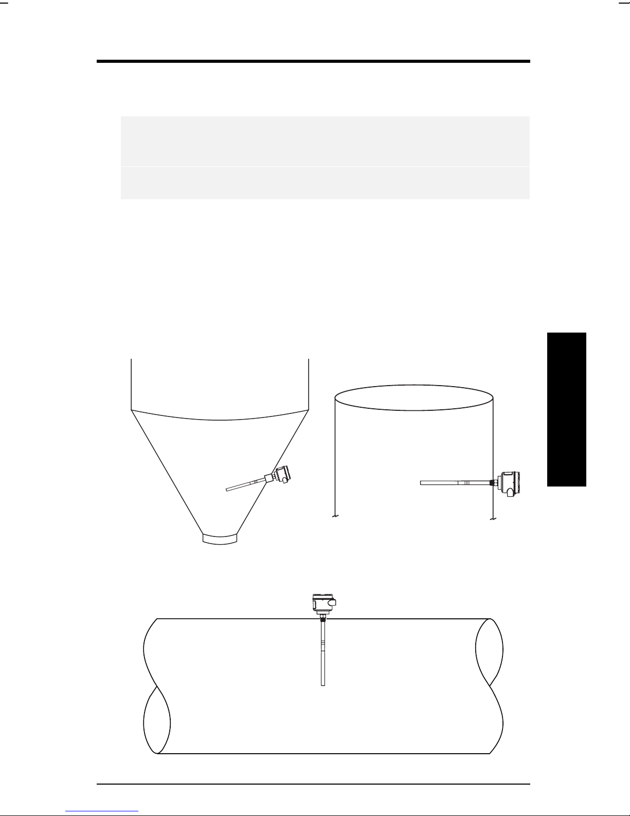
The Pointek CLS 300 as supplied in the standard probe lengths is normally
mounted on the vessel top (high detection alarm) or through the tank wall at
the detection level (high or low detection alarm).
The cable version is designed for top mounting. The cable suspends
vertically so that it reaches into the process at the desired detection level
(high or low detection alarm).
Angle Horizontal
Vertical
Installation
PL-577 Pointek CLS 300 Page 11
Page 12

Installation
Page 12 Pointek CLS 300 PL-577
Page 13

Configuration and Dimensions
191
(7.5”)
146
(5.8”)
insulated – 9mm (0.35”)
CABLE/ROPE
non insulated – 6mm (0.24”)
Ø32
(1.26”)
136
(5.4”)
181
(7.1”)
Configuration
PL-577 Pointek CLS 300 Page 13
Page 14

Standard Version
/
59 mm
(2.3”)
lid
lid clip
½” NPT
76 mm
(3”)
120 mm
(4.7”)
Installation
electronics
enclosure
active shield
probe
145 mm
(5.7”)
370 mm
(14.6”)
Page 14 Pointek CLS 300 PL-577
Ø19 mm
(0.75”)
Page 15

High Temperature Version
/
59 mm
(2.3”)
76 mm
(3”)
120 mm
lid
lid clip
½” NPT
(4.7”)
electronics
enclosure
active shield
probe
154 mm
(6.06”)
Configuration
361 mm
(14.21”)
PL-577 Pointek CLS 300 Page 15
Ø19 mm
(0.75”)
Page 16

Ceramic Active Shield Insulator
The High Temperature version, which includes a ceramic Active Shield
insulator, is recommended when the process temperature is greater than
200EC/ 392 EF and / or when the product to be detected is very abrasive. The
high temperature version is rated for applications up to 400 EC / 752 EF. See
Temperature and Pressure Recommendations for Application on page 33.
Thermal Isolator
If the ambient temperature of the transmitter is expected to exceed
85EC/185EF, then a thermal isolator should be used. An isolator provides a
separation distance between a high process temperature inside the vessel,
and the electronic housing outside the vessel. This reduces the operating
temperature of the electronics to a value equal or less than 85EC/185EF.
Rod Version
The rod version of the CLS 300 is available in standard lengths from 350
mm (14”) up to 1000 mm (40”). Other lengths using stainless steel or other
metals can be attached as an electrode to the customer’s requirement.
Ensure that the thread end conforms to the exact dimensions as shown
below. Lengths of rod are not recommended beyond 1000 mm (40”).
Installation
1.5 mm by 45
(0.06”)
3 mm
(0.12”)
12 mm
(0.47”)
Flat sides
= 18 mm
(0.71”)
Ø19 mm
(0.75”)
Ø11 mm
(0.43”)
9 mm
(0.35”)
M5
17 mm
(0.67”)
34 mm
(1.3”)
37 mm
(1.5”)
Page 16 Pointek CLS 300 PL-577
M10
Page 17

Changing the Probe’s Length
The probe’s length can be shortened in the field by cutting the electrode.
Warning:
To prevent damage, do not apply torque directly to the main probe
assembly.
Option 1
If the electrode can be removed from CLS 300 unit:
1. Remove the electrode by
releasing the set screw and
turning the threaded
electrode end counter
clockwise
2. Place the upper part of the
electrode in a vice as shown
in the Figure.
3. Use a wrench to loosen the
lower portion of the
electrode.
Option 2
If electrode CANNOT be removed from CLS 300 unit:
1. With unit mounted in place,
place two wrenches as
shown in the Figure.
2. Hold the upper wrench
steady and turn the lower
one counter-clockwise to
loosen the lower portion of
the electrode.
Configuration
PL-577 Pointek CLS 300 Page 17
Page 18

The Wrong Way
If the process connection itself is put in the vice, then the probe’s internal
parts will rotate along with the wrench, and the unit may fail.
Installation
Page 18 Pointek CLS 300 PL-577
Page 19

Cable
/
/
(
)
59 mm
(2.3”)
lid clip
½” NPT
electronics
enclosure
lid
76 mm
(3”)
120 mm
(4.7”)
145 mm
(5.7”)
nominal value
active shield
cable
insulated – 9mm (0.35”)
non insulated – 6mm (0.24”)
probe
weight
flexible
extension
(Customer
specified
length)
25 m
(82 feet)
max
250mm
9.85”
PL-577 Pointek CLS 300 Page 19
Cable
Ø32mm
(1.26”)
175 mm (6.9”)
Page 20

Cable Tensile Strength
The tensile strength of the cable at 1900 kg / 4188 lbs should not be
exceeded. It is also important to confirm that the load carrying capability of
the silo/tank roof is sufficient to withstand the actual force on the cable for
any conditions where the force is likely to be as great as 1900 kg / 4188 lbs.
A cable (rope) probe with a PFA jacket reduces the possible product build up
on the probe, thus also the tensile force on the cable.
Cable Weights
A standard weight with optional attachable butterfly enhancer is available for
the cable version. For lower dielectric constant materials (often in solids) the
butterfly weight is recommended, since it increases the change in
capacitance when the material comes in contact with the cable end. This
would be the case when the silo is quite tall (> 15 m/45 ft) and the dielectric
>>>>
constant is less than (
< 4)
r
Shortening the Cable
The cable can be shortened using either:
• An angle grinder (preferably with a disc suitable for stainless steel); or
• Wire cutters (suitable for piano cable
Ø6 – 9 mm).
To shorten the cable, proceed as follows:
1. If present, remove Butterfly from weight;
2. Loosen the three set screws and remove weight by pulling it from the cable;
3. Grind/cut the cable to the required length, remove rough edges from the
cable;
4. Insure that the cable strands are properly seated in the lay of the cable (i.e.
no wire strands sticking outside the normal cable profile). It is important to
insure that this step is properly done before continuing the assembly.
5. Push the weight onto the cable while at the same time rotating it counter-
clockwise about the cable, making sure that no cable strands are pushed
out of their position in the cable and that the cable is fully inserted;
6. Re-fasten the weight by tightening the three set screws;
7. Attach the butterfly to the weight again.
Cable
Page 20 Pointek CLS 300 PL-577
Page 21

Mounting
Multiple units
500mm
(20”) min
Mounting
500mm
(20”) min
Sensors must be 500 mm (20”)
apart.
Wall Restriction
500mm
(20”)
Mount diagonally if there is not
enough vertical space.
Note:
These drawings are
not to scale
50mm*
(2”)min
PL-577 Pointek CLS 300 Page 21
50mm*
(2”)min
* standard version
Page 22

Process Concerns
Mounting
keep out of path of falling material consider material angle of repose
500mm
(20”) min
protect probe from falling material
build up of material in active shield area does not affect switch operation
Page 22 Pointek CLS 300 PL-577
Page 23

Interconnection
Trip Amplifier
Loosen the lid clip and remove the enclosure cover.
Interconnection
Relay contact
8A – 250Vac
5A – 30Vdc
Identification label (underside of enc losure cover)
Solid state switch
100mA – 250Vac
100mA – 300Vdc
Notes:
• Switch and potentiometer settings are for illustration purposes only.
Refer to Set Up on page 27.
• Relay contact terminals are for use with equipment having no
accessible live parts and wiring having insulation suitable for at least
250 V ac.
• Maximum working voltage between adjacent relay contacts shall be
250 V ac
Warning:
All field wiring must have insulation suitable for at least 250 V ac.
PL-577 Pointek CLS 300 Page 23
Page 24

Relay Output Connection
Solid State Switch
Interconnection
Relay shown in de-energized state, K2
contacts rated for 8A at 250 Vac / 5A at
30 Vdc
Switch shown in de-energized state, K3
contact rated for 250 Vac / 300 Vdc 100
mA max 2 VA/2W max., non-polarized.
Solid state switch to customer’s
control or instrumentation device
Diode Protection
When driving an external relay with either the solid stated switch and / or
relay outputs using dc power, protection diodes must be connected in the
correct polarity across the relay coil to prevent possible switch / relay
damage due to the inductive spikes generated by the relay coil.
Switch capacity
100mA max.
relay coil
Customer supplied diode protection
2 VA/2W max,
250 Vac/300 Vdc.
Customer supplied diode protection
Page 24 Pointek CLS 300 PL-577
relay coil
Page 25

Ancillary 2-Wire Output Connection
Optically isolated
customer supplied
(Phoenix DEK-OE-%DC/48DC/100
or equivalent)
Interconnection
V dc
Refer to Power Connection
Nominal 24 Vdc 48 Vdc
DC volts 22-26 46-50
R (S) 120 234
Power Connection (3 or 4 wire connection)
12 – 250 V (ac or dc)
PL-577 Pointek CLS 300 Page 25
Page 26

Interconnection
Page 26 Pointek CLS 300 PL-577
Page 27

Operation
Set Up
Note:
Set up can be done in the field with the Pointek CLS 300 mounted into
process, or in the shop prior to mounting.
Dip Switch 1
Set on to change the alarm relay status immediately when the sensor
detects a change in frequency. Use this setting when time is critical.
Set off to change the alarm relay status with a delay by the amount set on
potentiometer #1 (P1). Use this setting when you want to slow the response
to account for turbulence or false readings.
Dip Switch 2
Set on to change the alarm relay status immediately when the sensor
detects a change in frequency. Use this setting when time is critical.
Set off to change the alarm relay status with a delay by the amount set on
potentiometer #1 (P1). Use this setting when you want to slow the response
to account for turbulence or false readings.
Dip Switch 3
Set off to indicate the Low fail safe selection.
Set on to indicate the High fail safe selection.
Dip Switch 4
Set on to test the delay of the alarm relays as set by the potentiometer #1
(P1).
Set off for normal operation.
Operation
Dip Switch 5
Set on for normal sensitivity on the sensor. Use this setting in situations
when you are measuring dry solids or non-conductive liquids.
Set off for low sensitivity on the sensor. Use this setting when you are
measuring conductive liquids or wet conductive solids which are likely to
build up.
PL-577 Pointek CLS 300 Page 27
Page 28

delay ‘on’
delay ‘off’
fail safe
delay test
sensitivity
Start Up
Indicators
Operation
Delay on
S1 - 1
On
Off
After the CLS is properly mounted and the switch bank set up, apply power
to the unit. The green LED (L3) lights to indicate the unit is powered and
operational.
Disabled Disabled High Test Normal
Enabled Enabled Low Normal low
Delay off
S1 - 2
Fail-safe
S1 - 3
Delay test
S1 – 4
Sensitivity
S1 - 5
The Pointek CLS uses three LEDs for visual indication of the following:
L1 (yellow), sensor status: when P2 is properly set, this LED is on when
the sensor is in contact with the process
material (material capacitance is greater
than the set point, P2). L1 is off when the
sensor is out of contact with the process
material (material capacitance is less than
the set point).
L2 (red), output status: this LED is an indication of the relay and
L3 (green), power: this LED is on when the Pointek CLS is
Proceed with the set up of the alarm output.
Page 28 Pointek CLS 300 PL-577
solid switch contact status. Refer to
Operation \ Output Status.
properly powered.
Page 29

Alarm Output
Alarm Output Status
Covered Un-covered
Setpoint Adjustment
In order to assist you in properly adjusting the alarm set point for reliable and
accurate detection of the process material, we have categorized the
materials and applications into two cases. Follow the setup procedure
associated with the case which includes your application.
Case 1:
This is the general case encountered in most applications, characterized by
the following:
• dry solids
• low viscosity liquids
• hygroscopic / wet solids
• high viscosity and high conductivity liquids
Operation
Case 2:
Interface detection: - e.g. liquid A / liquid B, foam / liquid
PL-577 Pointek CLS 300 Page 29
Page 30

Trip Amplifier
Case 1
Preamble:
• insure that L3 (green) is `on '
• turn both potentiometers, P1 and P2, fully ccw (counterclockwise)
• set S1 switches 1 to 4 `off ' and S1 switch 5 to `on' (normal sensitivity)
1. With sensor uncovered and a minimum 100 mm free space all around, turn
P2 cw until L1 (yellow) goes `on '.
2. Turn P2 ccw until L1 goes `off '.
Case 2
Operation
Preamble:
• insure that L3 (green) is `on '
• turn potentiometer P1 fully ccw (counterclockwise), and P2 fully cw
(clockwise)
• set S1 switches 1 to 5 `off '
1. Immerse the sensor in the material that has the lowest dielectric constant.
L1 (yellow) should be `on '. If not, S1 switch 5 should be set to `on' (normal
sensitivity).
2. Adjust P2 ccw until L1 goes `off '.
3. Immerse the sensor in the material that has the highest dielectric constant,
L1 should come `on '.
Delay
The alarm actuation can be delayed for either or both `on alarm' and `off
alarm' conditions. The selection is made by setting S1-1 and S1-2, refer to
Set Up \ Switch Bank. The amount of delay is adjustable from 1 to 60
seconds by setting potentiometer, P1.
Note:
After completing the set up, replace the Pointek CLS lid and lid clip. The
unit is now in service, providing level detection of your process.
Page 30 Pointek CLS 300 PL-577
Page 31

Troubleshooting
Symptom Observation Action
No alarm response L3 off (green LED) Check power supply
Check sensitivity, S1-5,
electrode, connections
to sensor input on trip
amplifier (and zener
barrier continuity if
used)
Check that relay and L2
(red LED) changes
state when S1-3 is
toggled
Alarm won’t switch
when material level
moves down the
electrode
L1 (yellow) doesn’t
respond to reducing level
on the electrode
L1 (yellow) responds to
reducing level on the
electrode
Alarm doesn’t
switch when
material level
moves up the
electrode
L1 (yellow) doesn’t
respond to the sensing
electrode approaching or
touching.
L1 (yellow) responds to
increasing level on the
electrode
L1 (yellow) flashes when
approaching the alarm
trip-point
Check sensitivity S1-5,
electrode, (and zener
barrier continuity, if
used)
Check that relay and L2
(red LED) changes
state when S1-3 is
toggled
Troubleshooting
PL-577 Pointek CLS 300 Page 31
Page 32

Maintenance
The Pointek CLS 300 requires no regular maintenance or cleaning. Even
with significant build-up on the CLS 300 level detector electrode, the level
switch will continue to operate. Build-up of material on the active shield area
will have little or no effect on the performance of the CLS 300.
Maintenance
Page 32 Pointek CLS 300 PL-577
Page 33

Appendix I: Application Notes
Application Notes
Temperature and Pressure Recommendations for Application
Note: 1 bar = 100 Pascals
PL-577 Pointek CLS 300 Page 33
Appendix I
Page 34

Appendix II: CE Conformity
WRITTEN DECLARATION OF
CONFORMITY
Appendix II
We,
Siemens Milltronics Process Instruments B.V.
Nikkelstraat 10 - 4823 AB BREDA - The Netherlands
Declare, solely under own responsibility, that the product
Point Level Switch, Pointek CLS 300
Mentioned in this declaration, complies with the following
standards and/or normative documents:
Requirements Remarks Certificate No.
EMC Directive 89/336/EEC Commercial, light
Industrial, and industrial
EN 55011: 1991 Emission – Class B
EN 50082-2: 1995 Generic Immunity Standard, from which:
• EN 61000-4-2: 1995: Electrostatic Discharge (ESD) Immunity
• EN 61000-4-3: 1996: Radiated Electro-Magnetic Field Immunity
• ENV 50204: 1995: Digital Radio Telephones Immunity
• EN 61000-4-4: 1995: Electrostatic Fast Transient (EFT) Immunity
• EN 61000-4-5: 1995: Surge Transient Immunity
• EN 61000-4-6: 1996: Conducted Radio-Frequency Disturbances
Immunity
97221-KRQ/EMC 004024
ATEX Directive 94/9/EC Audit Report No. 2003068
EN 50014: 1992 General Requirements
EN 50018: 1994 Flameproof Enclosures “d”
EN 50020: 1994 Intrinsic Safety “i”
EN 50284: 1999 Special Requirements for Category 1G
EN 50281-1-1: 1998 Dust Ignition Proof
Page 34 Pointek CLS 300 PL-577
II 1/ 2 GD EEx d
[ia] IIC T6…T1
Equipment
0344
T 100 °C IP 66
KEMA 00ATEXQ3047
KEMA 00ATEX2040X
Page 35

The notified body is: N.V. KEMA – Utrechtseweg 310 – 6812 AR
Arnhem – The Netherlands
Location: Breda Named Representative: C.S. van Gils
Date: October 1, 2000 Position: Managing Director
Note: For specific safety specifications, please consult the instrument
label
Appendix II
PL-577 Pointek CLS 300 Page 35
Page 36

Index
2-Wire Connection............................. 25
3 or 4 wire connection ....................... 25
About Pointek CLS 300 ....................... 5
Adjusting Probe Length ..................... 17
Alarm Output..................................... 29
Setpoint Adjustment ...................... 29
Status............................................ 29
Ancillary 2-Wire Output Connection ... 25
Angle of repose ................................. 22
Appendix ........................................... 33
Appendix II ........................................ 34
Application Notes .............................. 33
Applications ......................................... 5
Index
Approvals ............................................ 9
Cable................................................. 19
Shortening it .................................. 20
Tensile Strength............................ 20
Weights......................................... 20
Ceramic Active Shield Insulator......... 16
Certifications ....................................... 7
Configuration ..................................... 13
DECLARATION OF CONFORMITY .. 34
Dimensions ....................................... 13
High Temperature Version ............ 15
Standard Version........................... 14
Diode Protection................................ 24
Dip Switches ..................................... 27
Electrode
Shortening the Probe .................... 17
Enclosure cover
removing ....................................... 23
Falling Material .................................. 22
Features.............................................. 5
High Temperature Version................. 15
Dimensions ................................... 15
High Temperatures
Recommendations ........................ 16
Indicators........................................... 28
Installation......................................... 11
Location ........................................ 11
Interconnection.................................. 23
Ancillary 2-Wire Output Connection25
Diode Protection............................ 24
Power Connection......................... 25
Relay Output Connection .............. 24
Solid State Switch ......................... 24
Trip Amplifier ................................. 23
LEDs ................................................. 28
Location............................................. 11
Angle............................................. 11
Horizontal...................................... 11
Vertical.......................................... 11
Maintenance...................................... 32
Material build up ................................ 22
Mounting ........................................... 21
Multiple Units................................. 21
Process Concerns ......................... 22
Wall Restriction ............................. 21
Operation .......................................... 27
Alarm Output................................. 29
Set Up........................................... 27
Start Up......................................... 28
Output status ..................................... 28
Outputs................................................ 5
Pointek CLS 300 ................................. 5
Applications ..................................... 5
Configuration ................................. 13
Dimensions ................................... 14
Features.......................................... 5
Outputs ........................................... 5
Power................................................ 28
Power Connection ............................. 25
3 or 4 wire connection ................... 25
Power Supply ...................................... 7
Protection diodes............................... 24
Relay Output Connection................... 24
Rod Version ...................................... 16
Sensor status .................................... 28
Set Up............................................... 27
Dip Switches ................................. 27
Setpoint Adjustment .......................... 29
Shield Insulator.................................. 16
Shortening Probe............................... 17
Solid State Switch.............................. 24
Solid stated switch............................. 24
Specifications ...................................... 7
Standard Version............................... 14
Dimensions ................................... 14
Start Up............................................. 28
Thermal Isolator ................................ 16
Transmitter.......................................... 7
Trip Amplifier ..................................... 23
Troubleshooting................................. 31
Page 36 Pointek CLS 300 PL-577
Page 37

33455770
Rev 2.0
ISO 9001
Certificate #002284
Peterborough, Ont., Canada
R
E
G
I
S
T
E
R
E
D
Q
U
A
L
I
T
Y
S
Y
S
T
E
M
R
CANADA
GERMANY
SWITZERLAND
Singapore, Brazil
AUSTRALIA
BELGIUM
FRANCE
HONG KONG
MEXICO
THE NETHERLANDS
THE UNITED KINGDOM
THE UNITED STATES
www.milltronics.com
1954 Technology Dr., P.O. Box 4225,
Peterborough, Ontario, Canada K9J 7B1
Tel.: (705) 745-2431 Fax: (705) 741-0466
August van de Wielelei 97, 2100 Deurne, Antwerp, Belgium
Tel.: +32(0)3326 45 54 Fax: +32(0)3326 05 25
Parc de la Sainte Victoire, Bât. 5, 13590, Meyreuil, France
Tel.: +33 4 42 65 69 00 Fax: +33 4 42 58 63 95
Tel.: (524) 248-1561 Fax: (524) 248-1565
Nikkelstraat 10, NL-4823 AB Breda, The Netherlands
Tel.: +31(0)76 542 7 542 Fax: +31(0)76 542 8 542
709 Stadium Drive, Arlington, Texas U.S.A. 76011
Tel.: (817) 277-3543 Fax: (817) 277-3894
A joint venture in a sales office in and distributors in
56 countries.
Visit our web site at:
182 Normanby Rd., Box 339, South Melbourne, Australia
Tel.: +61 3-9695-2400 Fax: +61 3-9695-2450
Friedrichstrasse 69, D-76703, Kraichtal, Germany
Tel: +49 721 595 4607 Fax: +49 721 595 4937
1 Hoi Wan Street, Suite 602, Quarry Bay, Hong Kong
Tel.: +85 2-2856-3166 Fax: +85 2-2856-2962
Century House, Bridgwater Road, Worcester, England WR4 9ZQ
Tel: +44 1905 450500 Fax: +44 1905 450501
Printed in Canada
Paseo de Loma Dorada # 114, Loma Dorada, Querétaro, Qro. 76060
CP 168, Crêt de Plan 23, CH-1095 LUTRY
Tel. +41 21 791 58 28 Fax. +41 21 791 58 40
 Loading...