

Page 1

Pointek CLS 200
Capacitance Liquids/Solids
33455400
Rev 1.1
Instruction ManualInstruction Manual
PL-540
February 1998
Technology based. Customer driven.
Page 2

hank you for purchasing Milltronics products. We endeavour to design
T
equipment that is simple to use and reliable in its operation, with the aim
of satisfying our customers' needs.
Milltronics has been designing and manufacturing process equipment since
1954. Our fields of expertise include ultrasonic and capacitance level
measurement, in-line weighing of dry bulk solids and motion sensing.
Milltronics is established world wide through associate offices and
representatives. Our network is continually being refined to provide our
customers with first rate sales information, engineering assistance and after
sales support.
For more details on our products and service, please contact us and we will
provide you with a listing of the offices or representatives nearest you.
Page 3

ABOUT POINTEK CLS 200
Pointek CLS 200 is to be used only in the manner
outlined in this instruction manual.
The Pointek CLS 200 capacitance level switch provides output on high or low process material
levels. When the measured material approaches or contacts the switch’s probe, an increase in
capacitance is sensed and a high level alarm can be triggered. If a low level alarm is required
then the lack of material contact is sensed and this condition triggers the low level alarm.
Pointek CLS 200 Outputs
✓ One form ‘C’ (SPDT) relay
✓ One open isolated, non-polarized, solid-state switch
Pointek CLS 200 Features
NPT, BSP and 3A compliant Tri-clamp connections
✓
(other connections on request)
✓ Corrosion resistant construction, Kynar® and 316 stainless steel wetted parts
✓ 35m (115 ft) maximum insertion length
✓ Fully adjustable process alarm: level, time delay, and fail-safe mode
✓ Rigid extensions of standard and sanitary versions
✓ Cable version with customizable length
Pointek CLS 200 Applications
✓ Liquids, slurries, powders, granules, and solids
✓ Foods and pharmaceuticals
✓ Chemical and petrochemical
✓ High pressure and temperature
PL-540 3
Page 4

SPECIFICATIONS
Power: » 12 - 250 V ac/dc 50/60 Hz, 2 VA / 2 W max
Environmental: » location: » indoor / outdoor
» altitude: » 2000 m max
» ambient temperature: » -40 to 85 °C (-40 to 185 °F)
» relative humidity: » suitable for outdoor (Type 4X / NEMA 4X /
IP65)
» installation category: » II
» pollution degree: » 4
Process: » dielectric constant (
» temperature: » -40 to 125° C (-40 to 257° F)
» pressure: » standard and rigid extension versions
Alarm Output: » relay: » 1 form ‘C’ (SPDT) contact, rated 8 A at 250 V
» solid state switch: » rated 250 V ac / 300 V dc, 100 mA max
» time delay: » ‘on/off alarm’ selectable, 1 to 60 s adjustable
» hysterisis: » 2 mm (0.08")
» repeatability: » 2 mm (0.08")
» fail-safe operation
Electronics/Enclosure:» termination: » removable terminal block, 2.5 mm
» construction: » epoxy coated aluminum with gasket
» ingress protection: » Type 4X / NEMA 4X / IP65
» electrical: » 2 x
ε
r
)
:» 1.5 min
0 to 25 bar / 365 p.s.i. / 2500 kPa
gauge (nominal)
» cable version
0 to 10 bar / 150 p.s.i. / 1000 kPa gauge
(nominal)
ac / 5 A at 30 V dc, non-inductive
2
» optional thermal isolator, 316 stainless steel
1
/2" NPT conduit entry
max
PL-540 4
Page 5

Probe:
length, max. mounting * extension tensile, max. sensor
3
Standard 5.5 m (18 ft)
/4" NPT, 1" BSP,
1
/2" BSP,
1
316 stainless steel
Sanitary 5.5 m (18 ft) 1", 1 1/2" and 2", 3A
compliant Tri-clamp
Cable 35 m (115 ft)3/4" NPT, 1" BSP,
1
/2" BSP,
1
316 stainless steel
316 stainless
steel
316 stainless
steel
® **
Kynar
n / a Kynar
n / a Kynar
180 kg
Kynar®
(400 lb)
®
®
Approvals: » CE, CSA
®
Kynar
* other process connections available on request.
** for a chemical resistance list for Kynar, contact your local distributor.
FM, CENELEC, 3A, refer to device nameplate
NRTL/C
is a registered trade mark of ELF Atochem
PL-540 5
Page 6

INSTALLATION
LOCATION
Installation shall only be performed by qualified personnel
and in accordance with local governing regulations.
This product is susceptible to electrostatic shock.
Follow proper grounding procedures.
The Pointek CLS 200 standard probe length is normally mounted into the vessel top (high
detection alarm) or through the tank wall at the detection level (high or low detection alarm).
The extended versions are designed for top mounting. The probe suspends vertically so that it
reaches into the process at the desired detection level (high or low detection alarm).
vertical
PL-540 6
angle horizontal
Page 7
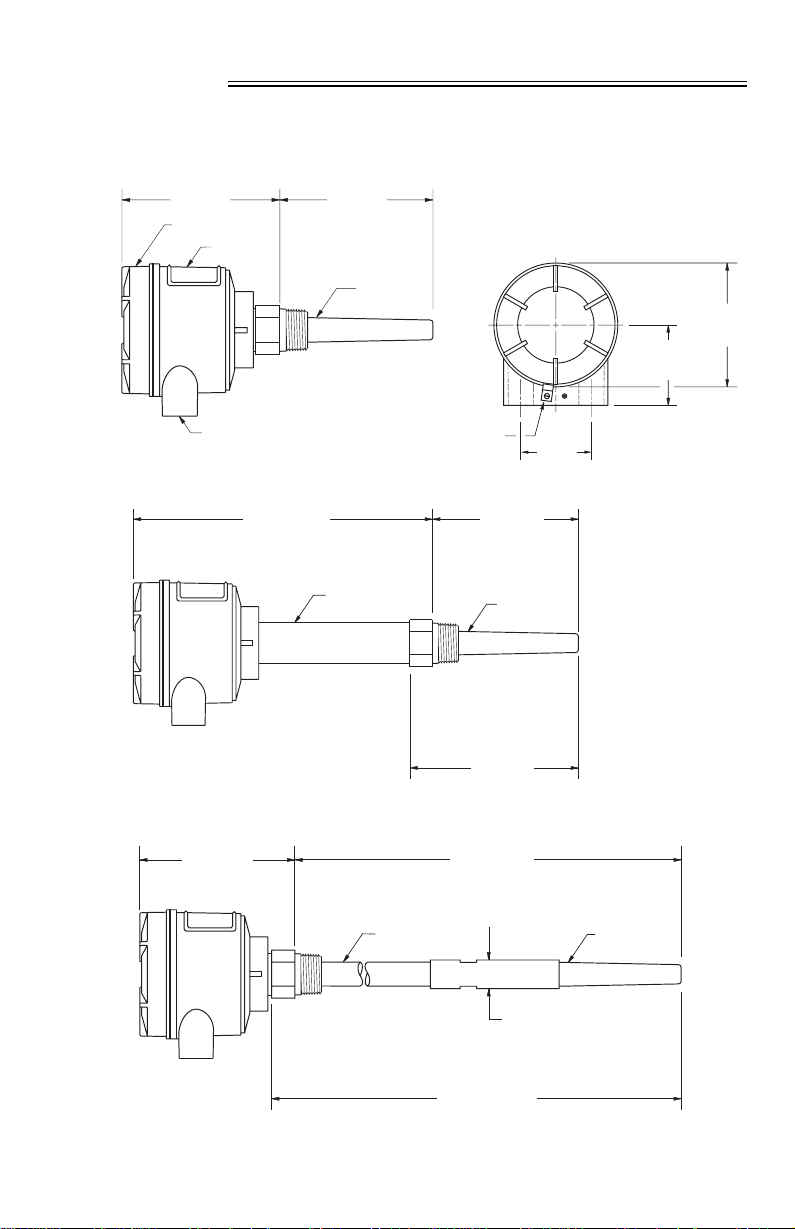
DIMENSION
CLS 200 VERSIONS
Standard
145 mm
(5.7")
lid
electronics /
enclosure
◆
120 mm
(4.7")
probe /
sensor *
120 mm
(4.7")
76 mm
(3")
1
/2" NPT
Standard with Thermal Isolator
245 mm
(9.7")
Standard with Extension
◆
145 mm
(5.7")
◆
thermal
isolator
extension
lid
clip
120 mm
probe*
5.5 m
(18 ft)
max
59 mm
(2.3")
(4.8")
sensor
sensor
* wetted parts are Kynar® and 316 stainless steel.
◆
nominal values
PL-540 7
20 mm (0.8") Ø
probe*
Page 8
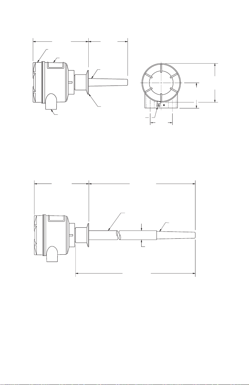
Sanitary
165 mm
(6.5")
lid
electronics /
enclosure
1
/2" NPT
Sanitary with Extension
165 mm
(6.5")
◆
100 mm
◆
(3.9")
probe /
sensor *
120 mm
(4.7")
76 mm
(3")
sanitary
Tri-clamp
lid
clip
◆
5.5 m
59 mm
(2.3")
(10 ft)
max.
* wetted parts are Kynar® and 316 stainless steel.
◆ nominal values
PL-540 8
extension
sensor
23 mm (0.9") Ø
probe*
98\03\30
Page 9

Cable
76 mm
(3")
lid
clip
59 mm
1
/2" NPT
(2.3")
flexible
extension *
120 mm
(4.7")
145 mm
(5.7")
nominal value
35 m
(115 ft)
max
lid
electronics /
enclosure
◆
cable
◆ to set the sensor at the
desired alarm point, by
shortening the cable,
refer to Appendix \
Shortening the Cable
for the proper procedure.
probe *
* wetted parts are Kynar
and 316 stainless steel.
®
PL-540 9
sensor
weight
20 mm
(0.8") Ø
sensor
Page 10

MOUNTING
DO’S AND DONT’S
STANDPIPES
MULTIPLE UNITS
< 50 mm (2")
> 100 mm
(4") Ø
100 mm
(4") min
100 mm
(4") min
Sensors must be 100 mm apart.
PL-540 10
100 mm
(4") min
Mount diagonally if there is
not enough vertical space.
Page 11

DO’S and DONT’S (cont’d)
WALL RESTRICTION
50 mm
(2")
min
50 mm
(2")
min
PL-540 11
Page 12

DO’S and DONT’S (cont’d)
PROCESS CONCERNS
keep out of path of falling material
protect probe from falling material
consider material angle of repose
50 mm
(2")
min
tensile load must not exceed probe
or vessel rating
avoid areas where material build up occurs
PL-540 12
Page 13

INTERCONNECTION
Loosen the lid clip and remove the lid.
identification label (underside of lid)
Switch and potentiometer settings are for illustration
purposes only. Refer to Operation \ Setup.
All field wiring must have insulation suitable for at least 250 V.
Relay contact terminals are for use with equipment having no accessible
live parts and wiring having insulation suitable for at least 250 V.
Maximum working voltage between adjacent relay contacts shall be 250 V.
PL-540 13
Page 14

RELAY OUTPUT CONNECTION
SOLID STATE SWITCH
relay shown in de-energized
state, K2 contacts rated for
8 A at 250 V ac /
5 A at 30 V dc
solid state switch to customer’s
control or instrumentation device
Switch shown in de-ene rgized state, K3 contact rated
for 250 V ac / 300 V dc, 100 mA max, non-polarized.
PL-540 14
98\03\30
Page 15

ANCILLARY 2-WIRE OUTPUT CONNECTION
optically isolated switch
customer supplied
refer to Power Connection
V dc
POWER CONNECTION
Nominal 24 V dc 48 V dc
V
dc
R
22 – 26 V 46 – 50 V
Ω
120
output
(Phoenix DEK-OE-5DC/48DC/100
or equivalent)
Ω
234
12 - 250 V
ac / dc
PL-540 15
Page 16

OPERATION
SET UP
Set up can be done in the field with the Pointek CLS mounted
into process, or in the shop prior to mounting.
Dip Switch 1
Set on to open the alarm relay immediately when the sensor detects a change in contact.
Use this setting when time is critical.
Set off to keep the alarm relay closed by the amount set on potentiometer #1 (P1).
Use this setting when you want to slow the response to account for turbulence or
false readings.
Dip Switch 2
Set on to open the alarm relay immediately when the sensor detects a change in
contact. Use this setting when you need the alarm to stop as soon as the contact
state changes.
Set off to keep the alarm relay closed by the amount of time set on potentiometer #1
(P1). Use this setting when you want to avoid false or early alarm relay cut outs due
to turbulence or false readings.
Dip Switch 3
Set on for fail-safe high alarm.
Set off for fail-safe low alarm.
Dip Switch 4
Set on to test the delay of the alarm relays as set by the potentiometer #1 (P1).
Set off for normal operation.
Dip Switch 5
Set on for normal sensitivity
on the sensor. Use this setting
in situations where you are
measuring dry solids or
non-conductive liquids.
Set off for low sensitivity
on the sensor. Use this
setting when you are
measuring conductive
liquids or wet conductive
solids which are likely
to build up.
switches shown in off position
PL-540 16
delay, ‘alarm on’
delay ‘alarm off ’
fail-safe
delay test
sensitivity
Page 17

delay on delay off fail-safe delay test sensitivity
S1 - 1 S1 - 2 S1 - 3 S1 - 4 S1 - 5
on disabled disabled high test normal
off enabled enabled low normal low
START UP
After the CLS is properly mounted and the switch bank set up, apply power to the unit. The
green LED (L3) lights to indicate the unit is powered and operational.
INDICATORS
The Pointek CLS uses three LEDs for visual indication of the following:
L1 (yellow), sensor status: when P2 is properly set, this LED is on when the sensor is
L2 (red), output status: this LED is an indication of the relay and solid switch
L3 (green), power: this LED is on when the Pointek CLS is properly powered.
Proceed with the set up of the alarm output.
in contact with the process material (material capacitance
is greater than the setpoint, P2). L1 is off when the sensor
is out of contact with the process material (material
capacitance is less than the setpoint).
contact status. Refer to Operation \ Output Status.
PL-540 17
Page 18

ALARM OUTPUT
ALARM OUTPUT STATUS
high
alarm
low
alarm
SETPOINT ADJUSTMENT
In order to assist you in properly adjusting the alarm setpoint for reliable and accurate
detection of the process material, we have categorized the materials and applications into
three cases. Follow the setup procedure associated to the case which covers your application.
Case 1:
Case 2:
Case 3
PL-540 18
this is the general case encountered in most applications, characterized
by the following:
- dry solids
- low viscosity liquids
demand applications, characterized by the following:
- hygroscopic / wet solids
- high viscosity and high conductivity liquids
: interface detection: - e.g. liquid A / liquid B, foam / liquid
Page 19

trip
point
delay
output
status
(red)
switches
sensor
status
(yellow)
power
(green)
Case 1
Preamble: - insure that L3 (green) is ‘
- turn both potentiometers, P1 and P2, fully
- set S1 switches 1 to 4 ‘
on
’
ccw
(counterclockwise)
off
’ and S1 switch 5 to ‘on’ (normal sensitivity)
1. With sensor uncovered and a minimum 100 mm free space all around, turn P2 cw
on
until L1 (yellow) goes ‘
’.
2. Turn P2 ccw until L1 goes ‘
off
’.
Case 2
Preamble: - insure that L3 (green) is ‘on ’
- turn potentiometer P1 fully
- set S1 switches 1 to 4 ‘
ccw
(counterclockwise), and P2 fully cw (clockwise)
off
’ and S1 switch 5 to ‘
off
’ (low sensitivity)
1. Adjust the material level of the process so that the sensor is immersed, L1 (yellow)
on
should be ‘
’. If L1 does not light, reset S1 switch 5 to ‘on ’ (back to normal
sensitivity; the appropriate position of S1 switch 5 depends on the dielectric
properties of the material).
2. Adjust the material level of the process so that the sensor is uncovered , but retains
significant (as much as possible) build up of material on the sensor.
3. Adjust P2 ccw until L1 ‘
adjust P2 cw then ccw a couple of times to insure that L1 is
off
’.To get the true feel of the correct position, it is wise to
off
just
‘
Case 3
Preamble: - insure that L3 (green) is ‘on ’
- turn potentiometer P1 fully
- set S1 switches 1 to 5 ‘
ccw
(counterclockwise), and P2 fully cw (clockwise)
off
’
1. Immerse the sensor in the material that has the lowest dielectric constant.
on
L1 (yellow) should be ‘
2. Adjust P2
ccw
until L1 goes ‘
’. If not, S1 switch 5 should be set to ‘on’ (normal sensitivity).
off
’.
’.
3. Immerse the sensor in the material that has the highest dielectric constant,
L1 should come ‘
on
’.
PL-540 19
Page 20

DELAY
The alarm actuation can be delayed for either or both ‘on alarm’ and ‘off alarm’ conditions.
The selection is made by setting S1-1 and S1-2, refer to Set Up \ Switch Bank. The amount of
delay is adjustable from 1 to 60 seconds by setting potentiometer, P1.
After completing the set up, replace the Pointek CLS lid and lid clip.
The unit is now in service, providing level detection of your process.
PL-540 20
Page 21

TROUBLESHOOTING
Symptom Observation Action
No alarm response L3 off check power supply
Alarm doesn’t switch when
sensor is uncovered.
Alarm doesn’t switch when
sensor is covered.
L1 doesn’t respond to
uncovering the sensor.
L1 responds to uncovering
the sensor
L1 doesn’t respond to
covering the sensor.
L1 responds to covering
the sensor
L1 flashes when
approaching the
alarm setpoint.
check sensitivity S1-5,
sensor (and zener barrier,
if used)
check that relay changes
state when S1-3 is toggled
check sensitivity S1-5,
sensor (and zener barrier,
if used)
check that relay changes
state when S1-3 is toggled
MAINTENANCE
The Pointek CLS requires no maintenance or cleaning.
PL-540 21
Page 22

APPENDIX
SHORTENING THE CABLE
Allowed in general purpose version only,
see device nameplate.
Preamble
Measure the actual length of the cable and subtract the desired length to determine the
length to be cut off in step 5.
e.g. actual length 10 m
desired length
- 9 m
excess = 1m
actual
length
desired
length
excess
length
1. Unscrew the cable gland, compression nut, to relieve the compression ferrule
and release the cable.
cable gland,
compression nut
sleeve
probe,
lower assembly
2. Unscrew the probe sleeve from the lower assembly using two wrenches (17 mm)
across the flats, exposing the leads (3) and tension block.
PL-540 22
Page 23

tension block
connection
3. Remove the insulation covering the solder connections.
4. Unsolder the connections.
Do not cut the connection to the probe leads, as this
can render them too short to work with later.
5. Remove the sheathing around the tension block. Remove the block for reuse in
step 7, and cut off the excess length of cable.
6. Remove approximately 6 cm (2.4") of cable jacket, shield and filler strands.
7. Replace the tension block and shorten the lead to approximately 4 cm (1.6").
8. Prepare the leads for soldering.
If heat shrink is to be used to insulate splices and sheath the tension
block (steps 9 and 11), remember to slip them on before soldering the leads.
9. Make the solder connections and insulate.
5 cm
(2")
tension block
10. Remove the excess core.
11. Sheath the tension block.
PL-540 23
core
98\03\30
Page 24

12. Re-dress the probe sleeve thread with Teflon tape or sealant.
13. Reassemble the sleeve and cable gland. Insure that the cable is not
turned excessively, as this could break the leads.
14. Check unit for proper operation.
PL-540 24
■
 Loading...