

Page 1
OPERATION
When the Quick Start procedure is complete...
1.
"----" is displayed briefly...
The AIRANGER DPL PLUS rapidly takes measurements,
verifies repeatability, and calculates Readings.
For one vessel, the Reading is displayed continuously.
For two vessels, Readings are scroll displayed.
Difference or Average Readings (if selected) are also scroll
displayed, as Point Number 3.
The Bar Graph indicates material level (0 to 100%),
regardless of the Operation selected.
If "▲" is displayed the vessel level has exceeded 80% and
not yet fallen below 75% (Hi Alarm).
If "▼" is displayed the vessel level has fallen below 20% and
not yet exceeded 25% (Lo Alarm).
When in alarm, the corresponding relay is de-energized.
Transducer # Alarm Relay #
2.
Readings are displayed in % (based upon Operation).
Empty
➞
3.
View mA output values in the Auxiliary Reading display.
Empty
➞
4.
View the Failsafe Time Left in % (before "LOE" is displayed).
If the value reaches 0, the "old" Reading, Bar Graph, relays,
and mA outputs are "held" and "LOE" flashes.
When a valid measurement is made, the value resets to 100.
The AIRANGER DPL PLUS advances to the "new" level;
operating displays and outputs accordingly.
to enter the RUN mode
1Hi1
1Lo2
2Hi3
2Lo4
%
level space or distance
Span = 0 ➞ 100% Empty ➞ Span = 100 ➞ 0%
level space or distance
Span = 4 ➞ 20mA Empty ➞ Span = 20 ➞ 4mA
5 6 1
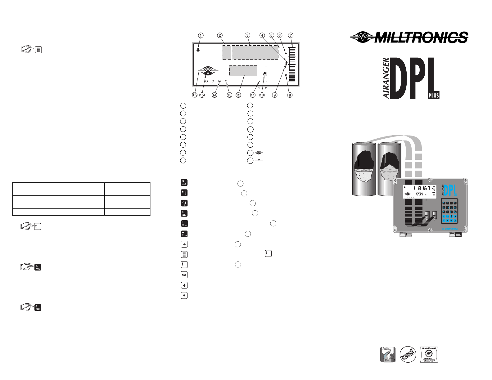
RUN MODE DISPLAY FUNCTIONS
100
%
1
1
Transducer
2
Point Number
3
Reading
4
Filling
5
Percent
6
Hi Alarm
7
Bar Graph
8
Lo Alarm
234
9
Emptying
10
Data Out
11
Point Scanned
12
Auxiliary Reading
13
Relay #4 energized
14
Relay #3 de-energized
15
Normal Operation
16
Failsafe Operation
0
RUN MODE KEYPAD FUNCTIONS
Display mA output in 12 .
Display temperature in 12 .
Display Empty / Fill Rate in 12 .
Display Failsafe Time Left in 12 .
Key in Parameter # to display value in 12 .
Display Material Level in 12 .
Display Distance in 12 .
Initiate program mode access ( see ).
Display Units / % in 3 (complete program mode access).
%
Stop / Start scroll display.
Display next Point Number (scroll display stopped).
Display previous Point Number (scroll display stopped).
%
PERFORMANCE EVALUATION
Monitor system performance, under all operating conditions.
If alternate display, relay, or mA output operation is required,
or "LOE" is displayed, see instruction manual PL-421.
Connect (or enable) alarm/control equipment only after
satisfactory performance is verified.
DUAL POINT LEVEL MONITOR
QUICK START GUIDE
100
%
1
234
ACCURATE, RELIABLE
LIQUID and SOLID LEVEL MEASUREMENT
with
CUSTOM GRAPHIC LCD,
VOLUME CONVERSION,
ANALOG mA OUTPUTS,
ALARM RELAYS,
& BIC-II SUPPORT
PL-431
September 1995
33454310
PRR 2.3
0
%
Page 2
GENERAL
Quick Start details the minimum recommended start up
procedure for most AIRANGER DPL PLUS installations.
Refer to the individual product instruction manuals for
complete installation and interconnection instructions for the:
AIRANGER DPL PLUS
Ultrasonic Transducers
TS-3 Temperature Sensors (if used)
BIC-II Buffered Interface Converter (if used)
To measure distances greater than 60 m (200ft), refer to the
AIRANGER DPL PLUS manual (PL-421).
Ensure all process control equipment is disabled until
satisfactory AIRANGER DPL PLUS performance is verified.
INITIAL START UP
1.
Place the programmer in the AIRANGER DPL PLUS
enclosure lid recess. The magnetic programmer base
holds it in place.
2.
Apply power to the AIRANGER DPL PLUS,
is displayed.
OFF
3.
During the following procedure:
a) If the selection desired is already displayed...
no entry is required. (Advance to the next step.)
b) If an entry error is made...
%
1
234
and try again.
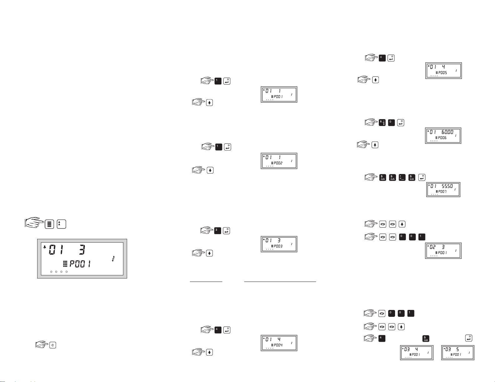
to enter the program mode
and display . . .
VESSEL # 1
STEP 1
(P001)
Which type of
off
0 =
level
1 =
space
2 =
distance
3 =
e.g. for level
STEP 2
(P002)
1 =
2 =
Which
liquid
solid
e.g. for liquid
STEP 3
(P003)
1 =
2 =
3 =
Which
slow
medium
fast
(Slower response improves measurement stability!)
e.g. for fast
STEP 4
(P004)
Which
ULTRASONIC
not entered
0 =
ST-25
1 =
ST-50
2 =
ST-100
3 =
LR-21
4 =
LR-13
5 =
e.g. for LR-21
Operation
is desired?
(point out of service)
(how full the vessel is)
(how empty the vessel is)
(from the transducer face)
1
234
to advance
Material
is being monitored?
(flat level surface)
(uneven sloped surface)
1
234
to advance
Measurement Response
(0.1 m/min)
(1 m/min)
(10 m/min)
1
234
to advance
Transducer
is connected (check nameplate)?
ULTRASONIC/TEMPERATURE
ST-H
100 =
XCT-8
101 =
XPS-10
102 =
XCT-12
103 =
XPS-15
104 =
XPS-30
105 =
1
234
to advance
is desired?
106 =
107 =
108 =
109 =
110 =
111 =
112 =
XPS-40
XLT-30
XLT-60
XLS-30
XLS-60
XKS-6
XRS-5
STEP 5
(P005)
1 =
2 =
3 =
Which measurement
metres (m)
centimetres (cm)
millimetres (mm)
Units
4 =
5 =
feet (ft)
inches (in)
are desired?
e.g. for feet
1
234
to advance
STEP 6
(P006)
Where is
(Presets Span to the maximum recommended value).
Empty
(transducer face to vessel bottom)?
0.000 to 9999
e.g. for 60 Units
1
234
to advance
STEP 7
(P007)
What is the
0.000 to 9999
Span
(Empty to highest material level)?
e.g.
1
234
To monitor 1 vessel, proceed to OPERATION.
VESSEL # 2
a.
b.
(switch to next vessel)
(return to STEP 1)
1
234
c. Repeat STEP 1 to 7
(Use the same STEP 5 value as for Vessel # 1).
To monitor 2 vessels, proceed to OPERATION.
DIFFERENCE or AVERAGE DISPLAYS
To display the difference or average of 2 vessels...
a.
b.
c. (difference) or (average) and .
or
1
234
Proceed to OPERATION.
1
234
432
 Loading...