

Page 1
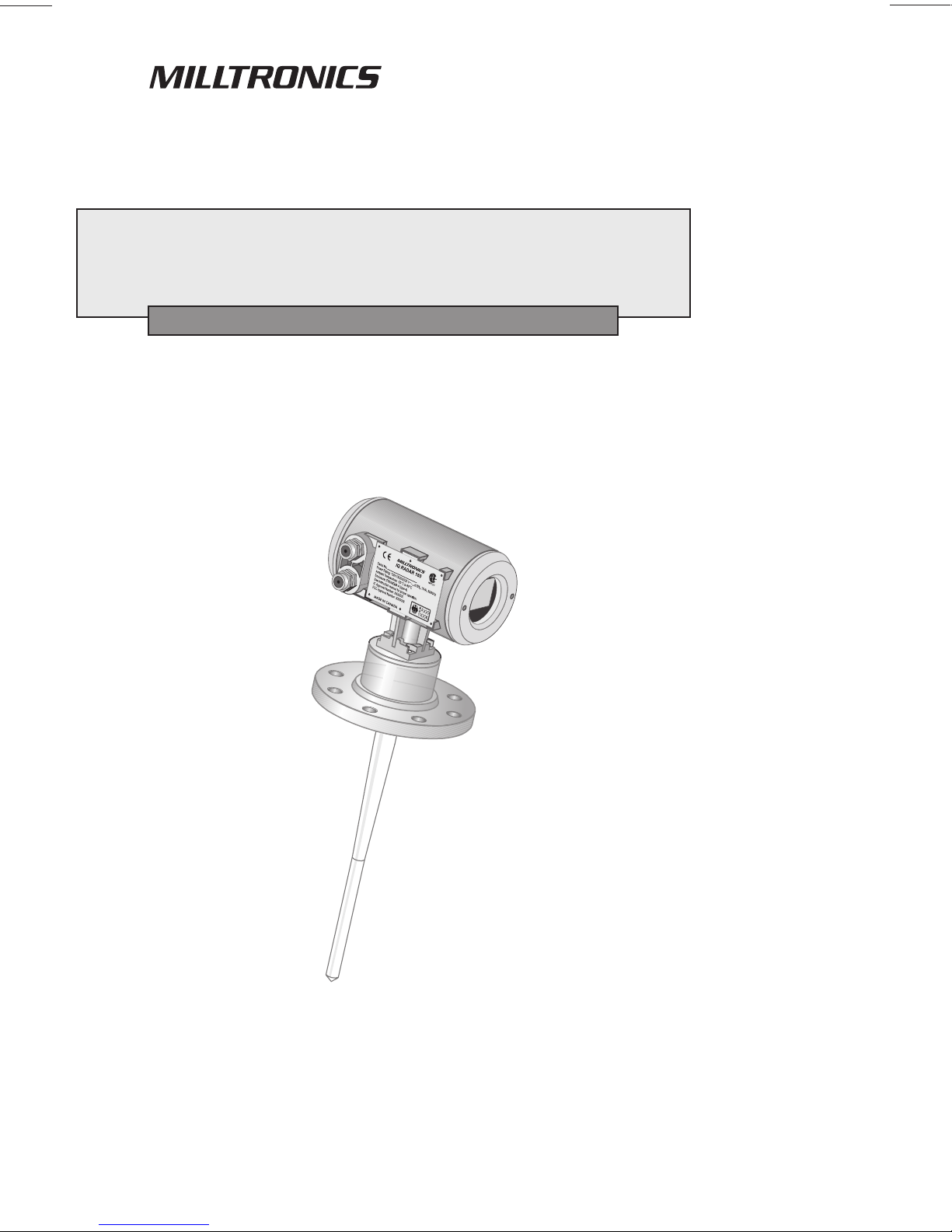
IQ RADAR 160
Instruction Manual PL-550
January 2001
33455500
Rev. 3.1
Page 2

Safety Guideline s
Warning notices must be obser v ed to ensure personal safety as w ell as that of others, and to
protect the product and the connected equipment. These warning notices are accompanied
by a clarification of the level of caution to be observed .
Qualified Personnel
This device/system may only be set up and operated in conjunction with this manual.
Qualified personn el ar e only authorized to install and operate this equipment in accordance
with established safety practices and standards.
Warning: This product can only function properly and safely if it is correctly transported,
stored, installed, set up , operated, and maintained.
Note: Always use p r od uct in accordance with specifications.
Copyright Siemens Milltronics Process
Disclaimer of Liability
Instruments Inc. 2000. All Rights Reserved
This document is available in bound version and in
electronic version. We encourage users to
purchase authorized bound manuals, or to view
electronic versions as designed and authored by
Siemens Milltronics Process Instruments Inc.
Siemens Milltronics Process Instruments Inc. will
not be responsible for t he contents of partial or
whole reproductions of eit her bound or electronic
versions.
MILLTRONICS®is a registered trademark of Siemens Milltronics Process Instrume nt s Inc.
Contact SMPI Technical Publications at the following address:
Technical Publicat ions
Siemens Milltronics Process Instruments Inc.
1954 Technology Drive, P.O. Box 4225
Peterborough, Ontari o, Canada, K9J 7B1
Email: techpubs@millt ronics.com
While we have verified the contents of
this manual for agreement w it h t h e
instrumentation described, variations
remain possible. Thus we cannot
guarantee full agreement. The
contents of this manual are regularly
reviewed and corrections are included
in subsequent editions. We w elcome
all suggestions for improvement.
Technical data subject to change.
For the library of SMPI instr uction manuals, visit our Web site: www.milltronics.com
© Siemens Milltronics Process Instruments Inc. 2001
Page 3

Table of Contents
General Information .........................................................................................5
About this Manual......................................................................................5
About IQ Radar 160/160 Ex......................................................................6
Specifications ................................................................................................... 7
IQ Radar 160/160 Ex................................................................................7
Installation.......................................................................................................11
Location ...................................................................................................11
Dimensions: Standard Unit with Rod Antenna.......................................12
Dimensions: Ex Unit with Rod Antenna.................................................13
Dimensions: Threaded Rod....................................................................14
Dimensions: Horn....................................................................................15
Dimensions: W aveguide Extension........................................................16
Dimensions: Sanitary Horn.....................................................................17
Dimensions: Sanitary Rod ......................................................................18
Dimensions: W aveguide.........................................................................19
Dimensions: Flanges ..............................................................................20
Mounting..................................................................................................21
Rod Asse m bly.........................................................................................23
Mounting: Rod Assembl y........................................................................24
Mounting: M anhole Covers.....................................................................25
Mounting: Horn Antennas.......................................................................25
Mounting: W aveguide Antenna..............................................................26
Mounting: Still pipe or Side pipe.............................................................27
Mounting: Horn with Waveguide Extensions.........................................28
Mounting: Sanitary Mounting..................................................................28
Mounting: Location/Beam Angle............................................................29
Interconnection ........................................................................................30
Start Up ............................................................................................................33
Overview..................................................................................................33
Display.....................................................................................................35
Aiming the Hand Programmer ................................................................35
Local Operation.......................................................................................36
Operation ........................................................................................................41
Overview..................................................................................................41
Transceiver..............................................................................................41
Los s of Echo............................................................................................42
Blanking...................................................................................................42
Analog Ou tput..........................................................................................43
Run / Pro gram .........................................................................................45
Application Example: Asphalt in Storage Tank......................................46
Application Exam p le: Horizo ntal Tan k with V olume..............................4 7
PL-550 IQ Radar 160/160 Ex Page 3
Page 4

Application Example: Juice Batch Tank with Sanitary Horn Antenna ..48
Application Example: Sliding Waveguide on Anaerobic Digesters.......49
Application Example: Stand Pipe .........................................................50
Parameter Descriptions..............................................................................53
Troubleshooting ......................................................................................... 63
Maintenance ...............................................................................................64
Appendix I....................................................................................................65
Alphabetical Parameter List .................................................................65
Appendix II...................................................................................................67
Appendix III..................................................................................................69
Temperature Derating ..........................................................................69
Rod Antenna ANSI Hole Pattern, 150# ................................................70
Rod Antenna DN Hole Pattern, PN16 ..................................................70
Rod Antenna Threaded Connection.....................................................71
Rod Antenna Sanitary Connection....................................................... 71
Horn Antenna or Wave Guide Still Pipe – ANSI Hole Pattern, 150#....72
Horn Antenna or Wave Guide Still Pipe DN Hole Pattern, PN16 .........72
Horn Antenna Sanitary Connection......................................................73
Appendix IV .................................................................................................75
BZT Approval – English........................................................................75
BZT Approval – German Original Text................................................. 76
Index.............................................................................................................77
Page 4 IQ Radar 160/160 Ex PL-550
Page 5

General Information
About this Manual
Refer to this manual for proper installation and operation of your IQ Radar
160/160 Ex.
General Information
Installation
Start-up
Operation
Applications
Parameters
Troubleshooting
gives you step-by-step direction for the installation and
interconnection of your IQ Radar 160/160 Ex.
instructs you in how to operate the keypad, program the
unit and read the display.
describes the operation of the IQ Radar 160/160 Ex.
looks at the IQ Radar 160/160 Ex from a practical point of
view, using a typical application example.
lists the parameters available to you, with a description of
their function and use. You are urged to read this section
to familiarize yourself with the parameters available to you
and get your IQ Radar 160/160 Ex working to its fullest.
tabulates symptoms, causes and actions to common
installation and application problems that you might
encounter. Hopefully you will never have to read this
section, but know it’s there to help you.
Appendices
An alphabetical cross-reference of the parameters and
their numbers, a record sheet for jotting down parameter
values, a Temperature Derating Chart, as well as a list of
approvals and certificates.
PL-550 IQ Radar 160/160 Ex Page 5
Page 6

About IQ Radar 160/160 Ex
The IQ Radar 160/160 Ex is to be used only in the manner outlined in this
manual.
IQ Radar 160/160 Ex is a versatile process material level monitoring
instrument. Material level measurement is achieved using advanced pulse
General Information
radar techniques. The unit consists of an electronic component coupled to the
antenna and process connection.
IQ Radar 160/160 Ex Features:
{
ANSI, DIN flange or sanitary tri-clamp mounting
{
corrosion-resistant construction, epoxy coated aluminium enclosure with
stainless steel flange and Teflon
{
local display
{
infrared keypad
{
Dolphin-compatible
IQ Radar 160/160 Ex Applications:
1
®
antenna and process seal.
{
liquids, slurries
process temperatures up to 200°C
{
vacuum and pressurized vessels
{
IQ Radar 160/160 Ex Approvals and Certificates
safety and radio
{
hazardous area
{
Note:
See Specifications on page 7 for an approvals listing and Appendix IV on
page 75 for approvals documentation.
1
Teflon is a registered trademark of Du Pont
Page 6 IQ Radar 160/160 Ex PL-550
Page 7

Specifications
Every attempt has been made to ensure the accuracy of these specifications,
however Milltronics reserves the right to change them at any time. Contact
your Milltronics representative for the most recent specifications.
IQ Radar 160/160 Ex
Power:
AC version:
{
DC version:
{
Fuse:
AC version:
{
DC version:
{
Interface:
analog output:
{
Dolphin/RS-485 link:
{
programmer link:
{
display (local):
{
Performance:
frequency:
{
accuracy at 20° C:
{
temperature drift:
{
measuring range:
{
repeatability:
{
fail-safe:
{
100/115/200/230 ±15% V ac2, 50/60 Hz, 15 VA
{
18 – 36 V dc, 15W
{
FU1, 2AG type, slow blow, .25 Amp, 250V
{
F1, 2AG type, slow blow, 0.375A, 250V
{
optically-isolated 0/4-20 mA into 750 Ω max, 0.02
{
mA resolution
refer to Dolphin Plus product specification
{
infrared receiver (refer to Programmer
{
specification on page 9)
backlit, alphanumeric and multi-graphic liquid
{
crystal for readout and entry
5.8 GHz (U.S.A. 6.3 GHz)
{
better than ±0.3% of range from 1 to 15 m
{
<±0.5% of range from –40 to 60° C (-40 to 392°F)
{
0.4 to 15 m
{
± 10 mm
{
mA programmable high, low or hold upon LOE
{
condition
Specifications
Mechanical:
Process Connections: Refer to Appendix III for pressure / temperature
flat faced flanges:
{
threaded connection:{316 stainless steel, 1-1/2” or 2”, NPT, BSP,G
{
sanitary connection:
{
2
Factory set – see device nameplate
PL-550 IQ Radar 160/160 Ex Page 7
limitations.
316 stainless steel, 2”, 3”, 4”, 50mm, 80mm,
{
100mm. Bolt hole pattern to ANSI & DIN types.
316 stainless steel, 2”, 3”, or 4” tri-clamp
{
Page 8

Antennas:
dielectric rod:
{
Teflon®3 (PTFE)
{
Ultra high molecular weight Polyethylene
{
(UHMW-PE
Length 41cm (16.3”) including integral gasket
{
4
)
horn:
{
waveguide:
{
Sanitary Antennas (FDA approved materials):
dielectric rod:
{
Specifications
horn:
{
Enclosure (electronic):
construction:
{
conduit:
{
ingress protection:
{
316 stainless steel
{
nominal diameters 100mm (4”), 150mm (6”),
{
200mm (8”)
emitter cone PTFE or UHMW-PE
{
waveguide extensions optional
{
316 stainless steel
{
emitter cone PTFE or UHMW-PE
{
one piece UHMW-PE4, optional PTFE
{
2”, 3”, 4” tri-clamp connection
{
304 stainless steel (316 special order)
{
horn with integral 4” tri-clamp connection
{
PTFE emitter
{
aluminium, epoxy coated
{
2 x 1/2" NPT or PG 16 entry
{
Type 6 / NEMA 6, IP-67
{
4
4
Weight:
6.5 kg (14.3 lb) with 2"/150 psi flange
{
weight will vary with flange size and rating
Environmental:
location:
{
altitude:
{
ambient temperature:{-40 to 60° C (-40 to 140° F)
{
relative humidity:
{
indoor/outdoor
{
2000 m max
{
suitable for outdoor
{
5
(Type 6/NEMA 6/IP 67 enclosure)
installation category:
{
pollution degree:
{
3
Teflon is a registered trademark of Du Pont
4
Not available for CENELEC EEx approval
5
See Temperature Derating on page 69 and Approvals on page 9.
II for ac version; I for dc version
{
4
{
Page 8 IQ Radar 160/160 Ex PL-550
Page 9

Process:
material dielectric:
{
εr > 1.8
{
(For εr < 3, you should use a wave guide antenna or
still pipe. See Mounting: Waveguide Antenna on page
26 or Mounting: Still pipe or Side pipe on page 27.)
temperature:
{
pressure (vessel):
{
UHMW-PE -40 to 80°C (-40 to 176°F)
{
PTFE -40 to 200°C (-40 to 392°F)
{
dependant on process connection type and
{
temperature. Refer to Appendix III on page 69 for
charts.
Approvals (refer to device nameplate):
safety:
{
radio:
{
hazardous areas:
{
IQ Radar 160:
{
(standard) and G, Class III.
IQ Radar 160Ex6:
{
CSA
{
BAPT, Industry Canada, FCC
{
CSA Class I/II, Div.2, Group A, B, C, D, F
{
CE, CSA
{
Cenelec/Sira7, EEx de IIB+H2 T6 (Note: antenna
{
NRTL/C
, CE, FM
NRTL/C
may be used in Zone 0 environments).
FM (USA) Class I, Div 1, Group A, B, C, D. Class
{
II/III, Div. 1, Group E, F, G (Class I, Zone 1 IIC
T6)
CSA Class I/II, Div. 1, Group B, C, D, E, F, G.
{
CE, CSA
{
NRTL/C
5
Specifications
FM (non-hazardous)
FM (non-hazardous)
Canadian Registration Number (CRN) for pressure fittings8:
{
Ontario, British Columbia, Alberta: OF6494.512
others pending
3A Sanitary
{
Contact Milltronics for complete and up to date list of approvals.
Programmer (remote keypad):
enclosure:
{
ambient temperature:{-20 to 50° C (-5 to 122° F)
{
interface:
{
power:
{
weight:
{
6
Cenelec: -20 to 40°C (-4 to 104°F), CSA and FM: -20 to 60°C (-4 to 140°F) ambient
7
Approved for PTFE material only
8
All process connections except for the sliding waveguide
general purpose
{
67 mm w x 100 mm h x 25 mm d
(2.6" w x 4" h x 1" d)
proprietary infrared pulse signal
{
9V battery (ANSI/NEDA 1604, PP3 or equivalent)
{
150g (0.3 lb)
{
PL-550 IQ Radar 160/160 Ex Page 9
Page 10

Specifications
Page 10 IQ Radar 160/160 Ex PL-550
Page 11

Installation
Location
Notes:
• Installation shall only be performed by qualified personnel and in
accordance with local governing regulations.
• This product is susceptible to electrostatic shock. Follow proper
grounding procedures.
• Do not mount in direct sunlight without the use of a sun shield.
Warning:
For vessels with conical or parabolic tops, it is not advisable to
mount the unit at the centre. Otherwise, the concavity of the top can
focus echoes into the centre, giving false readings.
Conical
Parabolic
Installation
Flat
PL-550 IQ Radar 160/160 Ex Page 11
Page 12
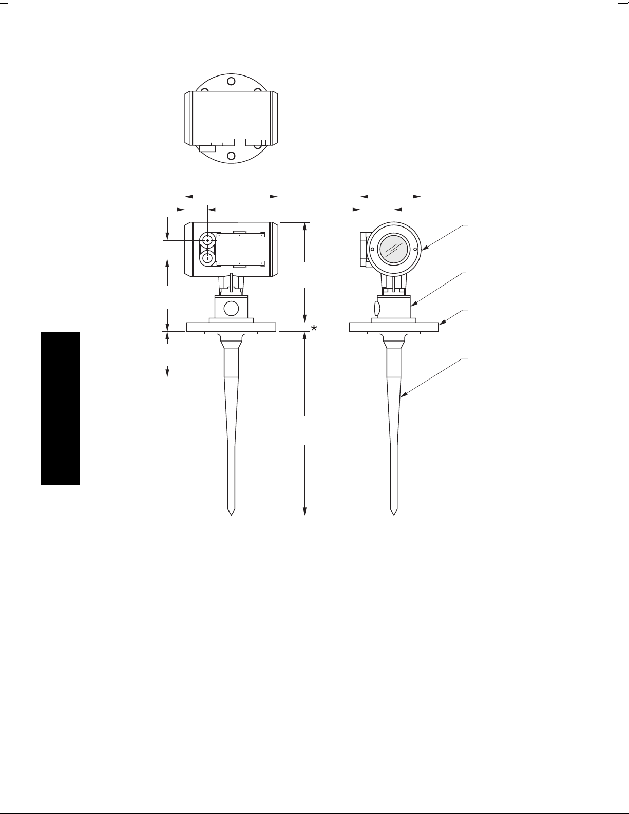
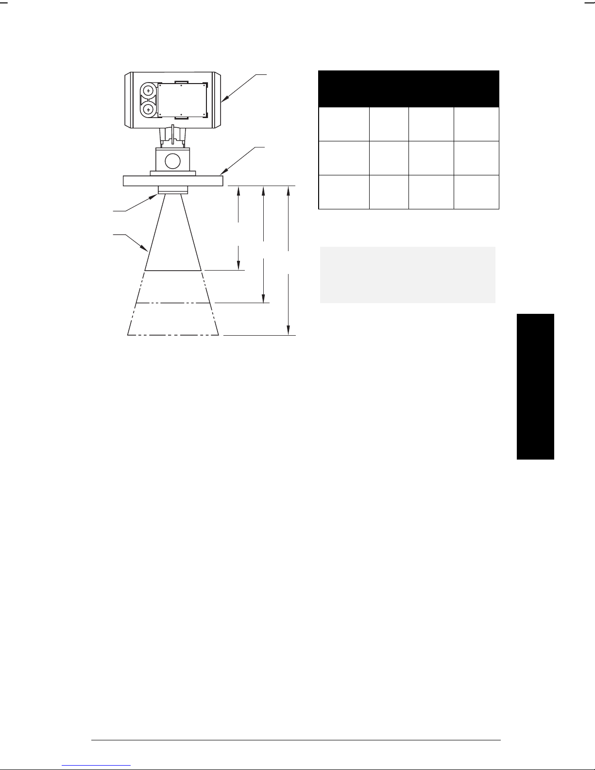
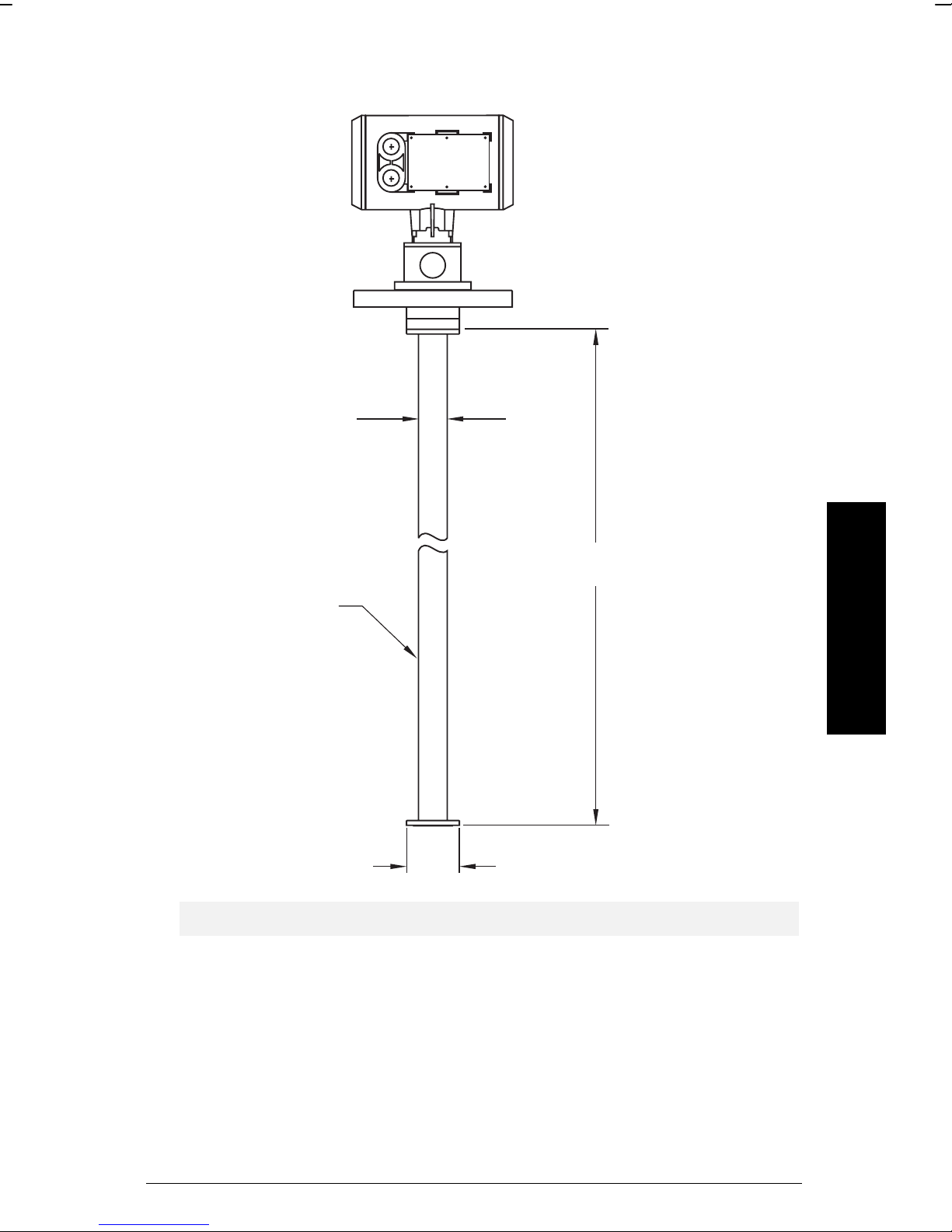
Dimensions: Standard Unit with Rod Antenna
(
)
(
)
(
)
*
Installation
50 mm
2.0"
41 mm(1.6")
183 mm
(7.2")
100 mm
(4.0")
211 mm
8.3"
245 mm
(9.6")
412 mm
(16.3")
136 mm
5.4"
75 mm
(3.0")
enclosure/
electronics
antenna
(resonator)
flange
antenna
(rod)
*
* Flange thickness 25 mm (1") nominal.
** Standard length, 50 and 100 mm (2” and 4") extensions available.
For information on temperature and pressure ratings, see Appendix III on
page 69.
Page 12 IQ Radar 160/160 Ex PL-550
Page 13
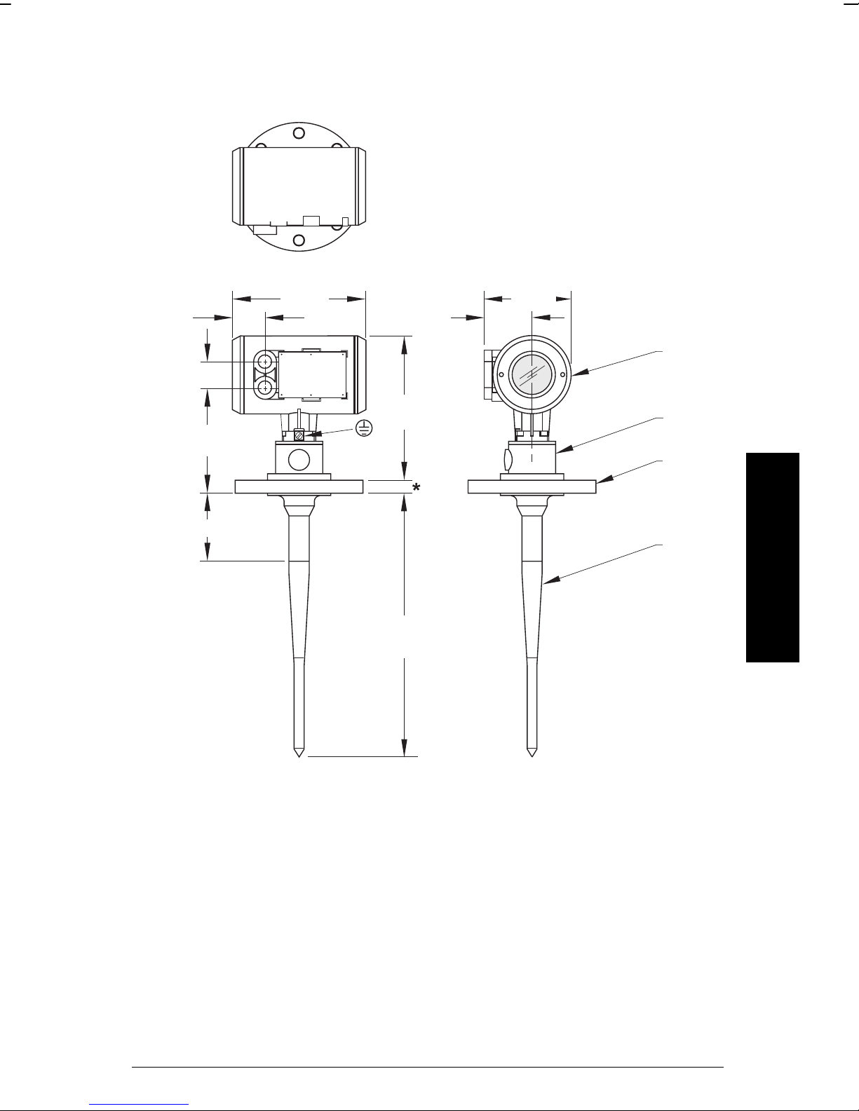
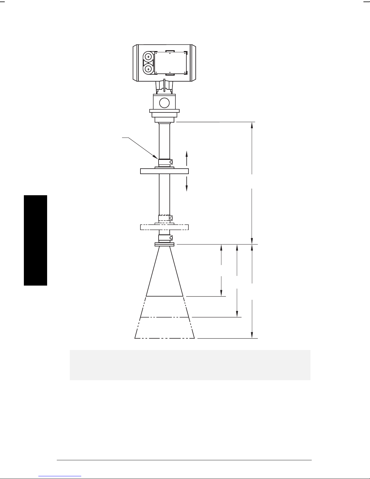
Dimensions: Ex Unit with Rod Antenna
(
)
(
)
(
)
(
)
*
64 mm
2.5"
41 mm (1.6")
183 mm
100 mm (4.0")
(7.2")
239 mm
9.4"
earth
connection
245 mm
(9.6")
412 mm
(16.3")
136 mm
5.4"
75 mm
(3.0")
enclosure/
electronics
antenna
(resonator)
flange
Installation
antenna
rod
*
* Flange thickness 25 mm (1") nominal.
** Standard length, 50 and 100 mm (2” and 4") extensions available.
For information on temperature and pressure ratings, see Appendix III on
page 69.
PL-550 IQ Radar 160/160 Ex Page 13
Page 14
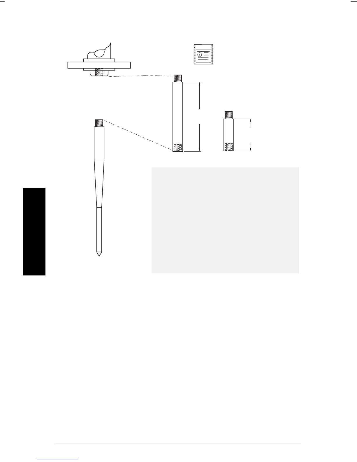
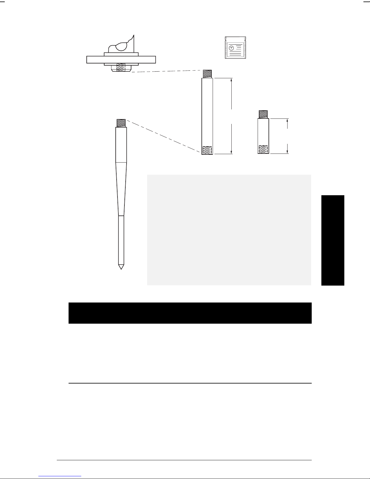
Dimensions: Threaded Rod
(4”)
optional
extension
Note:
Ingress of water or process fluids into the connecting
threads can cause reflections at the connection,
appearing as false echoes.
Teflon paste
(supplied)
100 mm
50 mm
(2”)
Installation
standard antenna
Apply Teflon paste to threads and tighten slowly.
Ensure that the rod sections mate securely with no
gaps. Do not apply too much Teflon paste or parts
will not mate securely.
Do not use wrenches or pliers. Hand tight only.
Sealant must have
εr < 3
. We recommend a sealant
such as Teflon paste or silicone compound.
Page 14 IQ Radar 160/160 Ex PL-550
Page 15
Dimensions: Horn
∅ 80 mm
(3”)
horn 131 mm
100 mm
(4”)
150 mm
(6”)
200 mm
(8”)
(5.16”)
enclosure /
electronics
flange
225.8 mm
325.1 mm
(12.8”)
Nominal
Horn
Size
100 mm
(4”)
150 mm
(6”)
200 mm
(8”)
Horn
O.D.
95.3
mm
(3.75”)
146.0
mm
(5.75”)
199.4
mm
(7.85”)
Horn
Height
131.0
mm
(5.16”)
225.8
mm
(8.89”)
325.1
mm
(12.8”)
Beam
Angle
28
degrees
20
degrees
12
degrees
Note:
Signal amplitude increases with horn
diameter, so use the largest size
practical.
Installation
PL-550 IQ Radar 160/160 Ex Page 15
Page 16
Dimensions: Waveguide Extension
optional sliding flange
(see flange table)
Note:
Always clamp the instrument in the
same position for operation.
(see P006 on page 53).
1000 mm
(40.8”)
Installation
131 mm
(5.16”)
225 mm
(8.89”)
325 mm
(12.8”)
Note:
1. Maximum pressure 0.5 bar at 60 deg. C (140 deg. F) for sliding flange
option.
Page 16 IQ Radar 160/160 Ex PL-550
Page 17
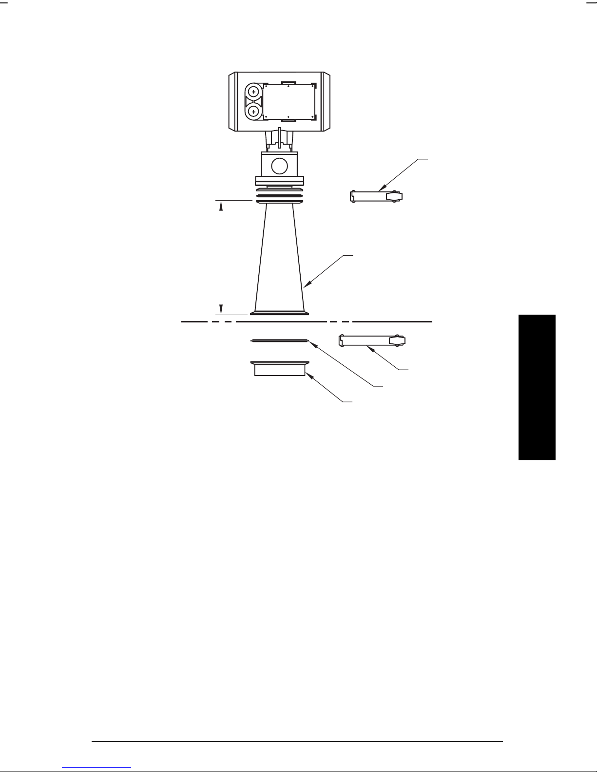
Dimensions: Sanitary Horn
Materials: standard optional
horn SS 304 SS 316
ferrule SS 304 SS 316
clamp SS 304 SS 316
gasket PTFE
50 mm (2”) clamp
(supplied)
232 mm
(9.13”)
horn
Installation
100 mm (4”) clamp (optional)
gasket (optional)
ferrule (optional)
PL-550 IQ Radar 160/160 Ex Page 17
Page 18
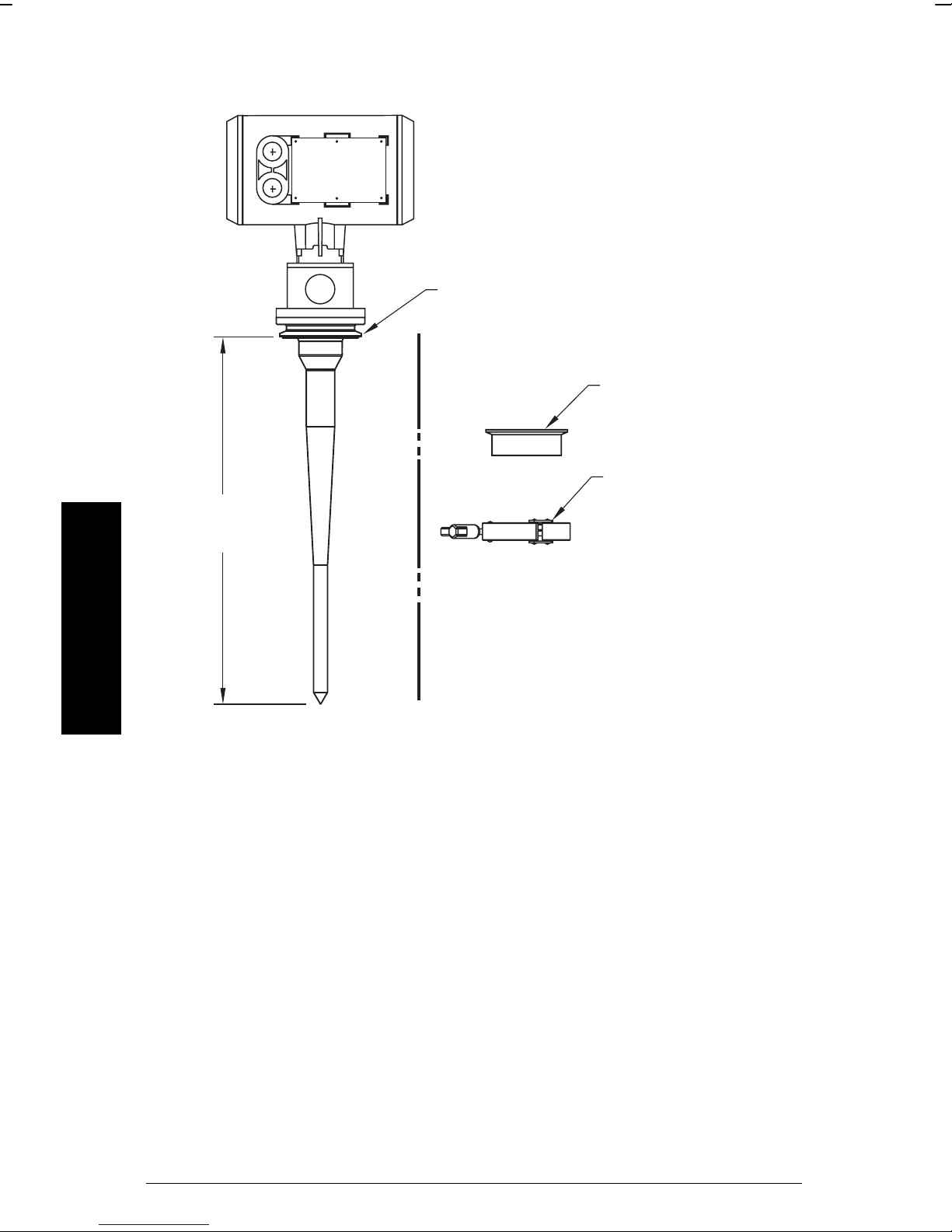
Dimensions: Sanitary Rod
50 mm (2”), 80 mm (3”) or 100 mm (4”)
with integral gasket
ferrule (optional)
clamp (optional)
406 mm (16”)
Installation
nominal
Materials: SS304 standard
SS316 optional.
Page 18 IQ Radar 160/160 Ex PL-550
Page 19
Dimensions: Waveguide
41.4 mm
(1.69”)
variable
waveguide
76.2 mm
(3.0”)
min: 100 mm (4.08”)
max: 6000 mm (244.90”)
Note: you can connect multiple waveguides together (maximum 2).
Installation
PL-550 IQ Radar 160/160 Ex Page 19
Page 20
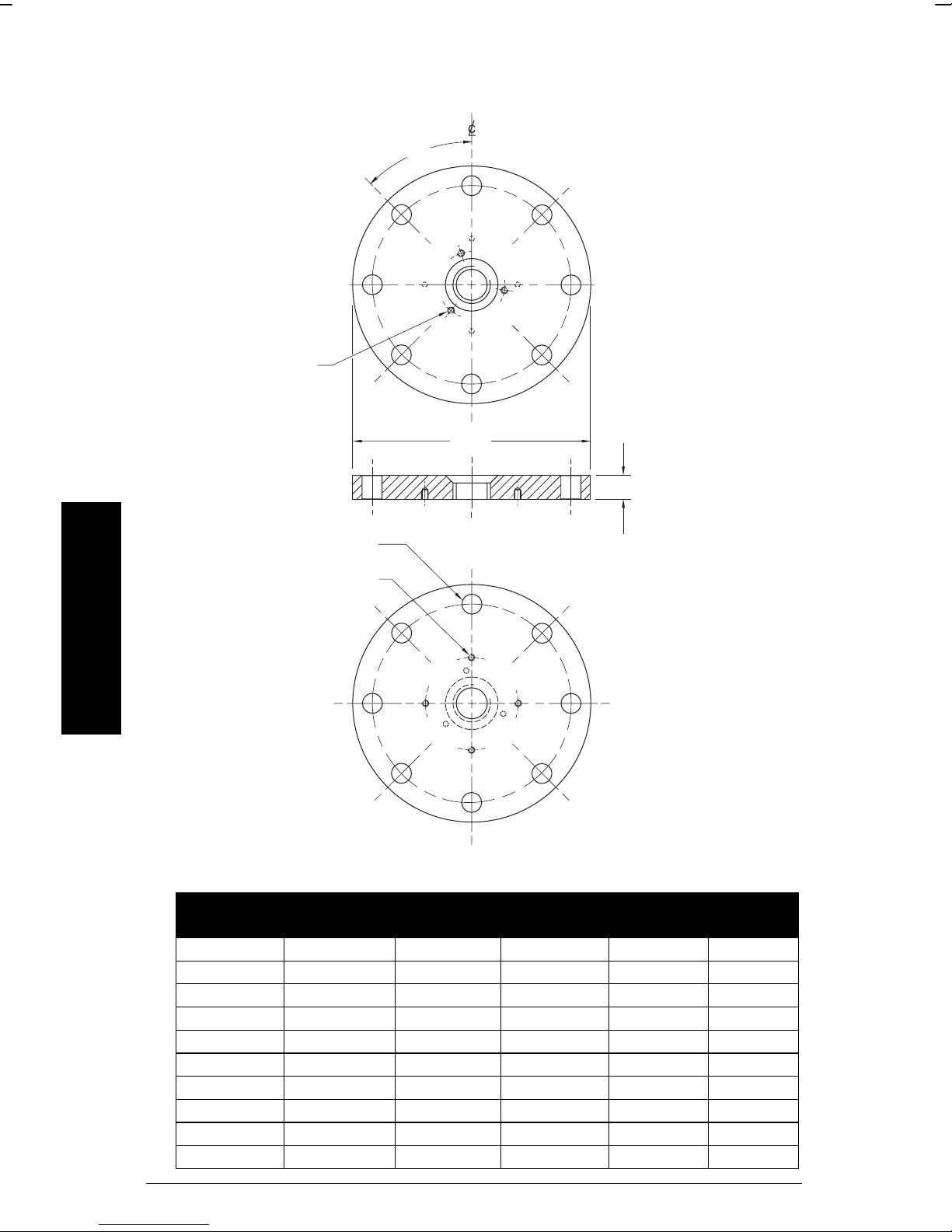
Dimensions: Flanges
45°
bolt hole
Installation
horn / waveguide
mounting holes
(threaded)
enclosure mounting
holes (threaded)
bolt hole
O.D.
bolt hole
circle
bolt hole
circle
process side
20 mm (0.8”), nominal
Pipe Size Flange
Size
2” ANSI 150# 6.0” 4.75” .7” 4
3” ANSI 150# 7.5” 6.0” .75” 4
4” ANSI 150# 9.0” 7.50” .75” 8
6” ANSI 150# 11.0” 9.50” .88” 8
8” ANSI 150# 13.5” 11.75” .88” 8
50 mm DN PN 16 165 mm 125 mm 18 mm 4
80 mm DN PN 16 200 mm 160 mm 18 mm 8
100 mm DN PN 16 220 mm 180 mm 18 mm 8
150 mm DN PN 16 285 mm 240 mm 22 mm 8
200 mm DN PN 16 340 mm 295 mm 22 mm 12
Page 20 IQ Radar 160/160 Ex PL-550
Flange
O.D.
Bolt Hole
Circle Ø
Bolt
Hole Ø
Number
of Bolts
Page 21
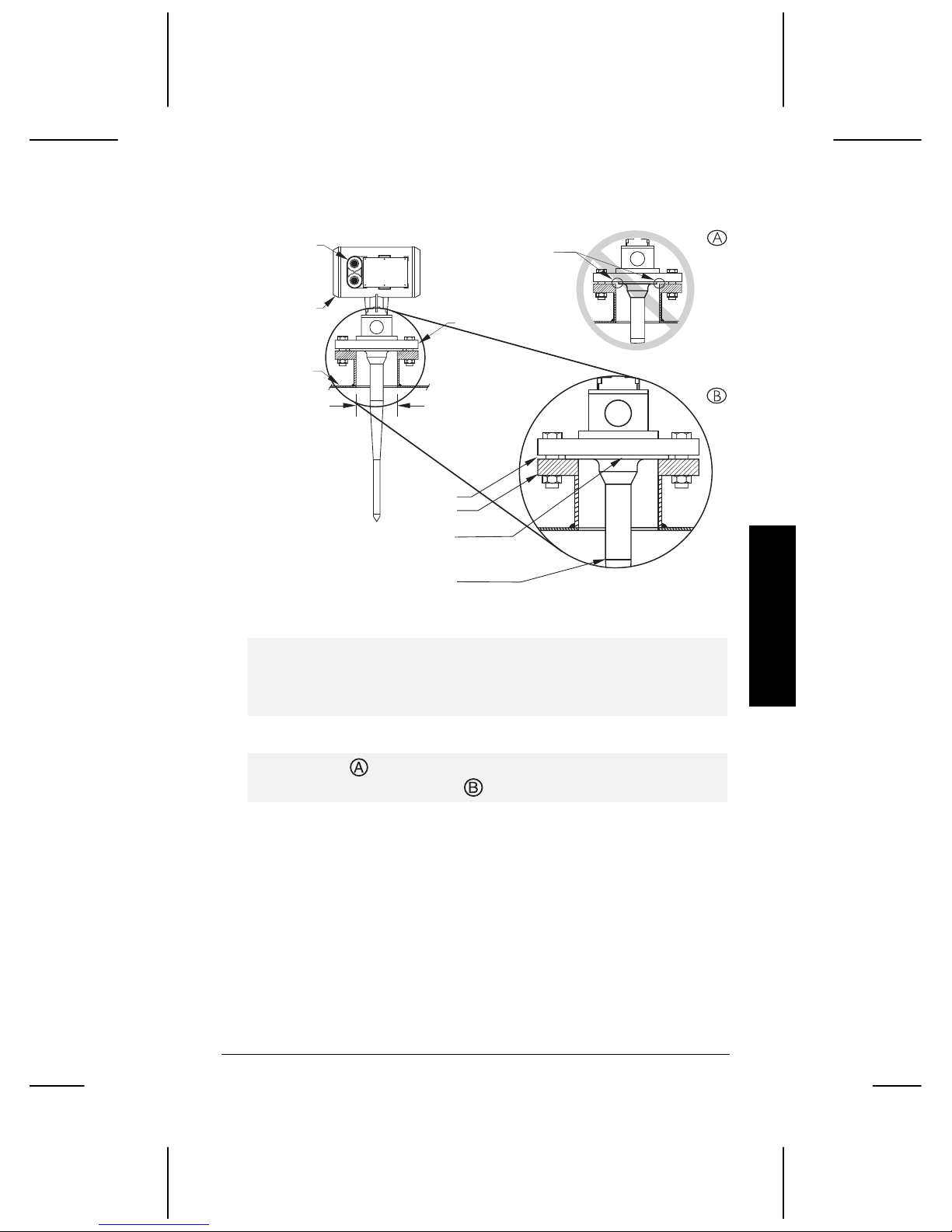
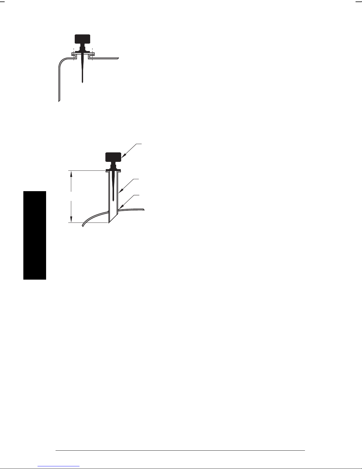
Mounting
1/2" NPT or PG
16 conduit entry
wiring access
cover
tank
minimum diameter
2" / DIN 50
standpipe/vessel jun cture
customer flange
integral process seal
*
see below
customer flanged
standpipe to suit
straight/taper transition
Notes:
• The straight/taper transition of the rod should extend past the
standpipe/vessel opening. Add extensions as required.
• Refer to the Rod Extension Requirements table.
• The unit in
is improperly mounted. The Integral process seal MUST
rest on customer flange as in .
Installation
PL-550 IQ Radar 160/160 Ex Page 21
Page 22
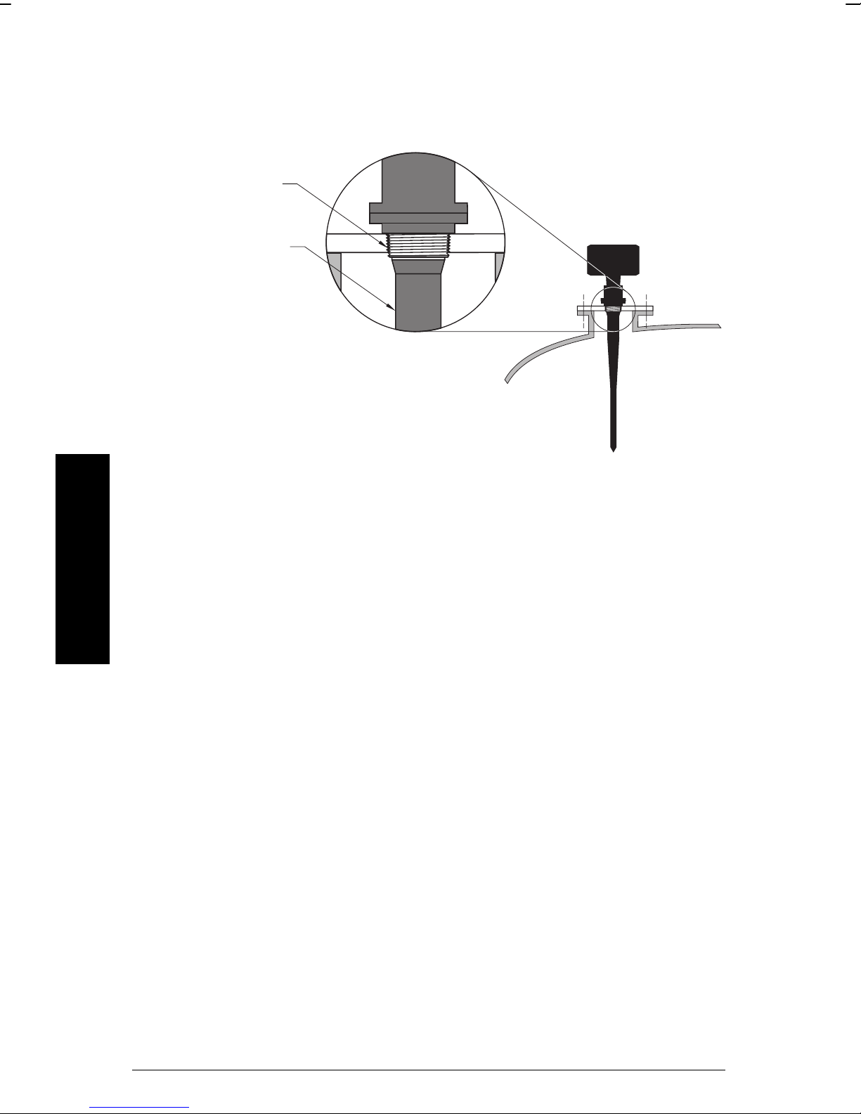
Threaded Rod Antenna
You can use 1.5” or 2” threaded process connections. There are three thread
types: NPT, BSP and G.
316 S.S.
PTFE or UHMW-PE
Wetted Parts:
Metal: 316SS
Polymeric: PTFE or UHMW-PE
Internal O-ring: Viton
Installation
Page 22 IQ Radar 160/160 Ex PL-550
Page 23
Rod Assembly
(4”)
optional
extension
Teflon paste
(supplied)
100 mm
50 mm
(2”)
Note:
Ingress of water or process fluids into the connecting
threads can cause reflections at the connection,
appearing as false echoes.
Apply Teflon paste to threads and tighten slowly. Ensure
that the rod sections mate securely with no gaps. Do not
apply too much Teflon paste or parts will not mate
securely.
Do not use wrenches or pliers. Hand tight only.
Sealant must have
as Teflon paste or silicone compound.
Rod Extension Requirements
standpipe i.d.
<100 (4) 100 to 150 (4 to 6) 150 to 200 (6 to 8)
50 mm (2”)n/r
80 mm (3”) n/r 50 mm 100 mm
100 mm (4”) n/r 50 mm 100 mm
150 mm (6”) n/r 50 mm 100 mm
>150 mm (6”) n/r n/r n/r
n/r extension not required
Consult Milltronics for assistance with standpipe sizes not listed.
*
application not recommended for 50 mm (2”) i.d. standpipes greater than 100 mm (4”)
**
long
standpipe height mm (inches)
εr < 3
. We recommend a sealant such
*
** **
Installation
PL-550 IQ Radar 160/160 Ex Page 23
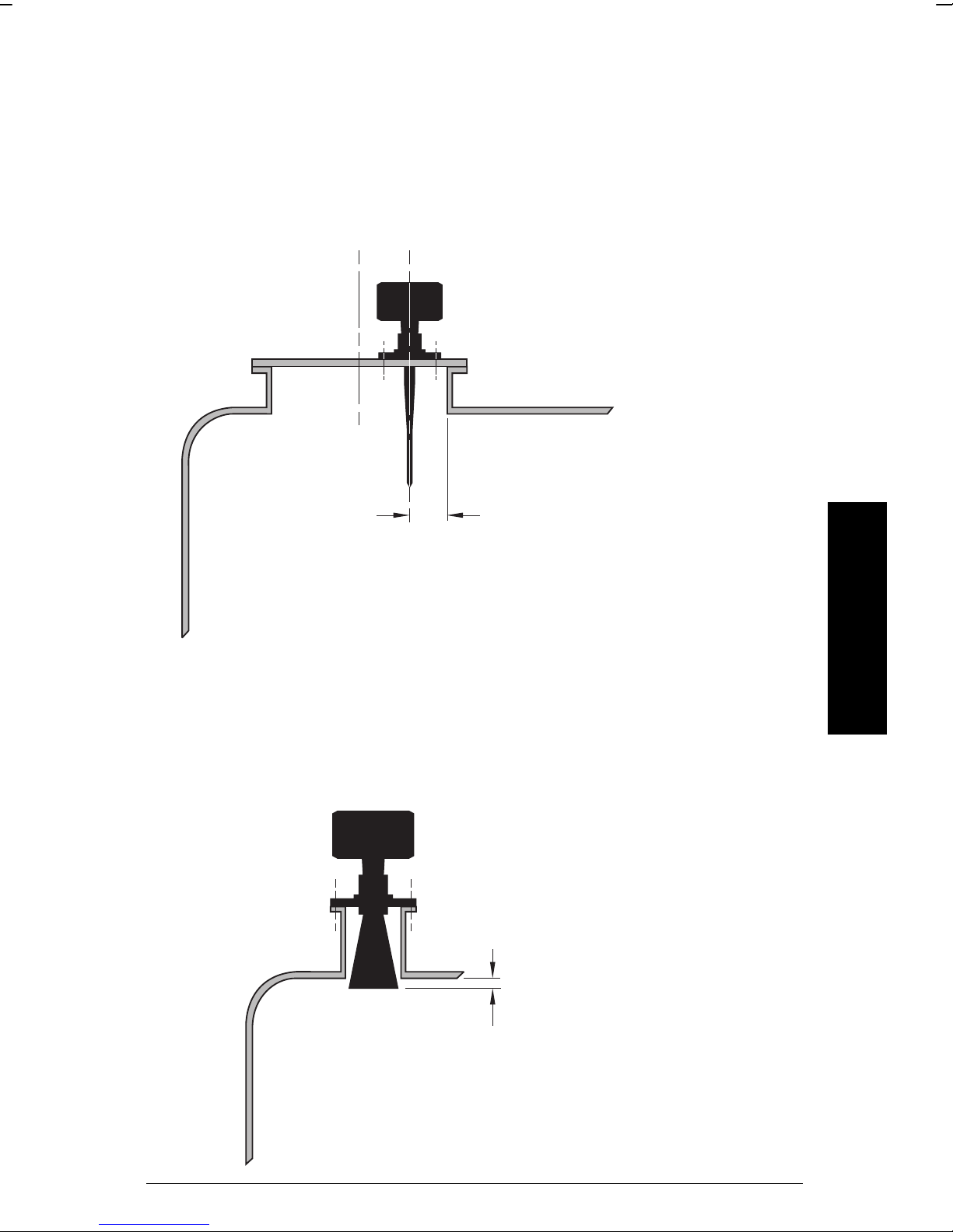
Page 24
Mounting: Rod Assembly
Ideally, the stand pipe should be as short as possible. If
your application requires a stand pipe that exceeds our
recommended maximum lengths, consider using a
waveguide and horn combination. If you create a new
stand pipe for the radar unit, ensure the weld seams are
on the outside of the stand pipe, not the inside.
Ensure that there are no seams or lips on the inside of
the stand pipe or you may get erratic readings.
If the mounting illustrated above is not suitable due to the minimum blanking
requirements, consider the following option:
enclosure
minimum diameter 100mm (4”)
A
Installation
Stand pipes that are 8” or larger in diameter provide excellent signal
conditions. These conditions allow for stand pipe lengths of up to 24” using
the standard rod without any extensions.
45
weld on outside
°
Maximum length 610 mm (24”)
No antenna extensions required
Page 24 IQ Radar 160/160 Ex PL-550
Page 25
Mounting: Manhole Covers
A manhole cover is typically a stand pipe that is 24” in diameter or greater and
that have a cover.
To provide the optimum signal conditions, locate the antenna off-centre with
respect to the cover, typically 100 mm (4”) from the side of the manhole.
100 mm (4”)
Mounting: Horn Antennas
Usually, horns are mounted on short stand pipes.
Installation
The end of the horn should
protrude a minimum of 10 mm
(0.5”) to avoid interference with
the stand pipe.
PL-550 IQ Radar 160/160 Ex Page 25
Page 26

Mounting: Waveguide Antenna
This option is recommended for products with εr lower than 3. The maximum
range of this application is reduced to 10 m (33 feet). See P655 on page 58.
vent hole
minimum 80 mm (3”)
Installation
Page 26 IQ Radar 160/160 Ex PL-550
Page 27

Mounting: Still pipe or Side pipe
An alternate to the waveguide antenna, this option is also used for products
with an ε
mounting arrangement can also be used to provide optimum signal conditions
on foaming materials.
Suitable pipe diameters are 2” (50 mm) to 10” (250 mm). A rod antenna or a
horn antenna may be used.
Note: The measurement range is reduced to 13 m (43’) for a 50 mm (2”)
still pipe or 14.5 m (47’) for a 80 mm (3”) still pipe.
Smoothness
One continuous length of metallic pipe is preferred (no joints). If joints are
required due to long length, then you must machine the joints to close
tolerances ± 0.25mm (± 0.010”) and weld a connecting sleeve on the outside.
less than 3 or for extremely turbulent or vortex conditions. This
r
vent hole
See P655 on page 58.
Installation
Suitable pipe diameters
are 2” (50mm) to 10”
(250mm).
You can use either a
Rod or Horn antenna.
Ensure there is a vent at the upper end of the surge pipe to equalize pressure
and keep the liquid level in the pipe constant with level in the vessel.
PL-550 IQ Radar 160/160 Ex Page 27
Page 28

Mounting: Horn with Waveguide Extensions
In applications where the stand pipe is too
long and the diameter is too small (such as a
stand pipe that is 100 mm (4”) in diameter
and 460 mm (18”) in length), the rod antenna
is not suitable due to stand pipe interference.
In this case, use the waveguide / horn
combination. Waveguide extensions are
available in custom lengths.
If the horn diameter is too large for the stand
pipe opening, you need to insert it from inside
the vessel. The horn must be connected to
the IQ160 process flange.
Note: The IQ160 maximum range of 15m is reduced by [0.64 x waveguide
length]. Blanking and offset parameters will be set by Milltronics, see the
device tag for values.
Mounting: Sanitary Mounting
There are two common sanitary mounting options; the 2”, 3” and 4” tri-clamp
Installation
with rod antenna and the sanitary 4” horn antenna.
Wetted Parts:
PTFE or UHMW-PE only.
Page 28 IQ Radar 160/160 Ex PL-550
Page 29

Mounting: Location/Beam Angle
Angle
Due to the polarization effect of
the microwave signal related to
the wall of the vessel, we
recommend locating the IQ160
a minimum of 30 cm (1’) away
from the side wall for every 3 m
Keep the emission cone
free of obstructions.
(10’) of vessel height.
Antenna Beam Angle
Rod 20
4” Horn 28
6” Horn 20
8” Horn 12
Beam
Polarization Effect
Mounting the unit too close to a wall may cause echoes to d isappear at
specific levels due to wave cancellation. A strong false reflection from an
internal tank obstruction can be reduced or eliminated by rotating the unit to
reduce the polarization effect.
False Reflections
Flat obstructions, and struts that are perpendicular to the emission cone,
cause large false reflections. They reflect the radar signal with high amplitude.
Round profile interfering surfaces diffuse reflections of the radar signals and
cause false reflections with low amplitude.
o
o
o
o
Installation
PL-550 IQ Radar 160/160 Ex Page 29
Page 30

Interconnection
IQ Radar 160 Terminal Block
IQ Radar 160 Ex Terminal Block
AC version DC version
1
mA
mA
2
SHLD
3
4A
5B
6
7
8
9
R
S
4
8
5
L2/N
L1
Installation
AC version DC version
Notes for both AC and DC versions:
• mA, RS-485, wiring, 14 – 20 AWG, shielded copper wire.
• Recommended torque on terminal clamping screws, 0.5 – 0.6 Nm
• Ground shields at one end only.
Page 30 IQ Radar 160/160 Ex PL-550
Page 31

IQ Radar 160 Wiring
AC version DC version
IQ Radar 160 Ex Wiring
AC version DC version
4-20 mA,
to instrumentation
RS-485,
to host device
to reliable
earth ground
V supply,
see nameplate
4-20 mA,
to instrumentation
RS-485,
to host device
V supply,
see nameplate
enclosure
Notes for AC version only:
• Line, 12 – 14 AWG, copper wire
• The equipment must be protected by a 15 A fuse or circuit breaker in
the building installation.
• A circuit breaker or switch in the building installation, marked as the
disconnect switch, shall be in close proximity to the equipment and
within easy reach of the operator.
Installation
All field wiring must have insulation suitable for at least 250 V.
Note for DC version only:
DC terminals shall be supplied from an SELV source in
accordance with IEC 1010.1 Annex H.
PL-550 IQ Radar 160/160 Ex Page 31
Page 32

Installation
Page 32 IQ Radar 160/160 Ex PL-550
Page 33

Start Up
Overview
The IQ Radar 160/160 Ex has two modes of operation:
When the unit is powered, after installation procedures have been completed,
run
it is programmed to start up in the
antenna flange to the target in meters.
Typical display
The unit can be placed into the
of program parameters in order to better suit the application or user’s
preferences. Programming can be carried out locally via the hand
programmer or remotely via the optional Dolphin/RS-485 interface.
program
mode, to detect the distance from the
mode at any time; to alter a number
run
and
program
.
PL-550 IQ Radar 160/160 Ex Page 33
Start Up
RS-485
hand programmer
Page 34

The first step in programming is to ensure that all parameters are at their
factory setting. The quickest way is to perform a master reset, P999 (see
page 61).
For a Quick Start, P001 to P007 are the key parameters requiring entry.
They set:
• mode of measurement
• process material
• antenna configuration
• measurement response
• units
• empty distance
• span
There are a number of other program parameters that can be changed
subsequently or during another programming session. Refer to the Parameter
Description that starts on page 53, for a list of the parameters available.
When programming has been completed, the IQ Radar 160/160 Ex can be
put into
run
by pressing, or exiting Dolphin.
Hand Programmer
Start Up
Page 34 IQ Radar 160/160 Ex PL-550
Page 35

Display
Aiming the Hand Programmer
Start Up
PL-550 IQ Radar 160/160 Ex Page 35
Page 36

Local Operation
Run Display
bar graph
representation of
material level, 0 to
100% of span
reading
units
reading questionable,
appears during fail-safe
operation
auxiliary reading
Program Display
Start Up
parameter type
(measurement of mA output)
= normal reading
= fail-safe operation
parameter value
units
Page 36 IQ Radar 160/160 Ex PL-550
parameter number
Page 37

Hand Programmer
Function
Keys
Numeric and
Auxiliary Keys
Key Programming Mode Run Mode
to
End program session and
Parameter scroll-up
Parameter scroll-down
Enter the displayed value
Values
Decimal point
Negative value
Clear value
run
enable
mode
“mA output value”
Toggle between units
and % on reading display
Initiate and complete
program mode access
“Distance”
Start Up
PL-550 IQ Radar 160/160 Ex Page 37
Page 38

Local Programming
To Access Program Mode
run
mode
Press
To Access a Parameter
Scroll Access
Press
Direct Access
Press
Initial program starts
at P000
Scroll up or down
e.g. P000 accessed
Press
Start Up
Page 38 IQ Radar 160/160 Ex PL-550
index parameter field
e.g. P005 accessed
Page 39

To Modify a Parameter Value:
Note:
Security must be disabled!
Changing Parameter Values
Select parameter
e.g. P001 = 3
Press
Clearing a Parameter Value
Press
Press
Resetting a Parameter Value
e.g. P001 = 1
e.g. field entry = 2
e.g. P001 = 1
e.g. P001 = 1
Press
To Access Run Mode:
Press
PL-550 IQ Radar 160/160 Ex Page 39
Reset to factory value
P001 = 3
from
program
exit and return to
run
Start Up
Page 40

Start Up
Page 40 IQ Radar 160/160 Ex PL-550
Page 41

Operation
Overview
The IQ Radar 160/160 Ex is a level measuring device for use with liquids and
slurries. Using advanced pulse radar technology, the device calculates
material level by first emitting a series of radar pulses and then analyzing their
reflections.
The device consists of an enclosed electronic component, mounted to a
flanged antenna component. The electronic component generates a 5.8 GHz
(U.S.A. 6.3 GHz) radar signal, which is directed to the antenna, waveguide, or
horn.
The radar signal is emitted axially from the antenna and propagates along this
axis in a defined conical beam decreasing in strength at a rate inversely
proportional to the distance.
The radar pulse detects the interface between the dielectric constant of the
atmosphere, and that of the material being measured. Electro-magnetic wave
propagation is not sensitive to the temperature and atmospheric conditions or
variations in the vessel.
The series of echoes from the pulses transmitted are sensed by the antenna
during the receive period of the electronics. The echoes are stored as a
profile of the activity in the vessel. The profile is analysed and the distance of
the material surface to the radar antenna is determined. This distance is used
as a basis for display of material level and mA output.
Transceiver
The IQ Radar 160/160 Ex transceiver operates under 1 of 5 sets of preset
conditions (P003), summarized as follows:
parameter
value
1 0.1 m/min slow on on 100
2 1 m/min • on on 10
3 10 m/min • on on 1
4 100 m/min • off on 0.1
5 1000 m/min fast off off 0
measurement
response
echo
verification filter
fail-safe
timer
Operation
When the echoes are received, the relevant echo extraction technique (P820
and P830) is applied to determine the true material echo.
PL-550 IQ Radar 160/160 Ex Page 41
Page 42

The measurement response limits the maximum rate at which the display and
analog output respond to changes in measurement. It is of concern especially
where liquid surfaces are in agitation or fall into the radar path during filling.
Loss of Echo
A loss of echo occurs when the IQ Radar 160/160 Ex deems that the
calculated measurement is unreliable, i.e. the confidence (P805) is less than
the threshold (P804). Refer to Troubleshooting on page 63.
If the condition persists for a time beyond the limit as set by the fail-safe timer
(P070), the confidence icon changes from full to partial (see page 36) and the
reading and mA output are immediately forced to the fail-safe default (P071).
Upon receiving a reliable echo, the loss of echo condition is aborted (icon
returns to full) and the reading and mA output return to the present level
immediately.
Blanking
Near blanking (P800) is used to ignore the zone in front of the antenna where
false echoes (e.g. ladder rung) appear as an echo during the receive cycle.
This is usually indicated by an incorrect high level reading and can be
overcome by increasing the near blanking from its factory set value.
Far end blanking is a feature that ignores the zone below the zero or empty
level where false echoes can appear at levels that interfere with the
processing of the true echo.
Typical Receiver Signal
end of
transmit
P800
near blanking
0
level
far end blanking
empty distance to antenna
Operation
Page 42 IQ Radar 160/160 Ex PL-550
P006
range extension
(P801) as % P006
range
Page 43

In applications where the zero level is above the bottom of the vessel and it is
desired to monitor the zone below the normal zero, range extension (P801)
can be used to extend the range into the far end blanking. Range extension is
entered as a percentage of P006. As range extension reduces the protection
afforded by the far end blanking, it should be used judiciously. Avoid
excessive range extension as this can reduce the measurement’s reliability
and accuracy. Range extension is factory set for 5% of P006. If it is found that
false echoes are appearing, after the blanking zone, P801 should be
increased accordingly.
Analog Output
The IQ Radar 160/160 Ex can be programmed to provide an analog output
(P200) of 0 to 20 or 4 to 20 mA, and for proportional or inverse span.
Programming
Upon entering the Program mode, the analog output level holds its prior
value.
PL-550 IQ Radar 160/160 Ex Page 43
Operation
Page 44

Run
The analog output responds in the following manner:
Level
(P001=1)
Space
(P001=2)
0/4 – 20 mA
(P200 = 1 or 2)
20 – 0/4 mA
(P200 = 3 or 4)
Distance
(P001=3)
*reference value only. mA level limited by near blanking.
0 and 100% are percentage of full scale reading (m, cm, mm, ft, in)
Volume
To program the unit for volume, set:
• operation (P001) to level “1” (see page 53),
• tank shape (P050) to a value other than 0 (see page 55),
• other volume parameters (P051 to P053) as required.
Operation
Page 44 IQ Radar 160/160 Ex PL-550
Page 45

Fail-Safe
When the fail-safe timer (P070) expires, the mA output responds as follows:
Fail-safe Mode (071) Status (0/4 – 20) Status (20 - 0/4)
high 22 0/2
low 0/2 22
hold hold hold
Run / Program
When the IQ Radar 160/160 Ex changes from
longer responds to the process. The last measurement is stored and the
associated reading and mA output are held.
As a courtesy, the unit reverts to the parameter last addressed during the
previous program session.
run
Upon return to
output default to the last measurement taken. The reading and associated
outputs migrate to the current process level at a rate controlled by the
measurement response (P003).
If the IQ 160/160 Ex is left in
reverts to
Run
, the transceiver resumes operation. The reading and mA
Program
mode.
mode for 10 minutes, it automatically
run
to
program
, the unit no
PL-550 IQ Radar 160/160 Ex Page 45
Operation
Page 46

Application Example: Asphalt in Storage Tank
Note:
The minimum distance from the antenna face to the target is limited by the
near blanking, P800.
The application is to obtain a level
measurement and corresponding 4-20
mA output proportional to asphalt levels
in a storage tank. The bottom of the
antenna flange is 5 m from the tank
Empty
(P006)
Span
(P007)
bottom. The empty level is 0 m (bottom)
and the full level (span) is 4.5 m from
the bottom. The maximum rate of filling
or emptying is about 0.1 m/min. In the
event of a loss of echo, the IQ Radar
160/160 Ex is to go into fail-safe Hi after
2 minutes.
Asphalt build-up on the rod antenna
does not effect performance.
Reset:
P999 master reset
Program:
P001 enter ‘1’ mode of measurement = level
P002 enter ‘1’ material = liquid
P003 enter ‘2’ measurement response = 1m/min.
P004 enter ‘240’ antenna
= dielectric rod,
standard length
P005 enter ‘1’ units = metres
P006 enter ‘5’ empty distance = 5 m
P007 enter ‘4.5’ span = 4.5 m
P070 enter ‘2’ fail-safe timer = 2 min.
P071 enter ‘1’ fail-safe = Hi
P820 enter ‘1’ algorithm = factory
P830 enter ‘4’ TVT type = factory
Run:
Press run to start normal operation. Press
.
Operation
Page 46 IQ Radar 160/160 Ex PL-550
Page 47

Application Example: Horizontal Tank with
Volume
Note:
The minimum distance from the antenna face to the target is limited by the
near blanking, P800.
The application is to obtain a level measurement and corresponding 4-20 mA
output proportional to material levels in a chemical tank. The bottom of the
antenna flange is 3.5 m from the tank bottom. The empty level is 0 m (bottom)
and the full level (span) is 3.0 m from the bottom. The maximum rate of filling
or emptying is about 0.1 m/min. In the event of a loss of echo, the IQ Radar
160/160 Ex is to go into fail-safe Hi after 2 minutes.
500 mm
(20.4”)
3000 mm
(122.4”)
Reset:
P999 master reset
Program:
P001 enter ‘1’ mode of measurement = level
P002 enter ‘1’ material = liquid
P003 enter ‘2’ measurement response = 1m/min.
P004 enter ‘240’ antenna
= dielectric rod,
standard length
P005 enter ‘1’ units = metres
P006 enter ‘5’ empty distance = 3.5 m
P007 enter ‘4.5’ span = 3 m
P050 enter ‘7’ tank shape = parabolic ends
P051 enter ‘8000’ maximum volume = litres
P052 enter ‘.8’ tank dimension A = metres
P053 enter ‘6’ tank dimension L = metres
P070 enter ‘2’ fail-safe timer = 2 min.
P071 enter ‘1’ fail-safe = Hi
P820 enter ‘6’ algorithm = first echo
P830 enter ‘4’ TVT type = factory
Operation
Run:
Press run to start normal operation. Press
PL-550 IQ Radar 160/160 Ex Page 47
.
Page 48

Application Example: Juice Batch Tank with
Sanitary Horn Antenna
Note:
The minimum distance from the antenna face to the target is limited by the
near blanking, P800.
Sanitary Antenna Options:
• One-piece antenna/process seal
• This provides an excellent mounting method, even on non-sanitary
installations.
P006
mixer
4” sanitary horn
existing 4” tri-clamp connection
P007
mixer
Operation
Page 48 IQ Radar 160/160 Ex PL-550
Page 49

Reset:
P999 master reset
Program:
P001 enter ‘1’ mode of measurement = level
P002 enter ‘1’ material = liquid
P003 enter ‘2’ measurement response = 1m/min.
P004 enter ‘240’ antenna
= dielectric rod,
standard length
P005 enter ‘1’ units = metres
P006 enter ‘5’ empty distance = 5 m
P007 enter ‘4.5’ span = 4.5 m
P070 enter ‘2’ fail-safe timer = 2 min.
P071 enter ‘1’ fail-safe = Hi
P652 enter tag value offset correction = factory
P820 enter ‘1’ algorithm = factory
P830 enter ‘4’ TVT type = factory
Run:
Press run to start normal operation. Press
.
Application Example: Sliding Waveguide on
Anaerobic Digesters
Blanking, P800 and offset P652 are set at the factory. Check the device tag
for specific values.
Maximum level should be maintained at
least .46 m (18”) from the end of the horn.
The raised position is for installation and
maintenance. The lowered position is for
horn
operation. Program the unit for operation
in the lowered position.
P006
P007
PL-550 IQ Radar 160/160 Ex Page 49
Operation
Page 50

Reset:
P999 master reset
Program:
P001 enter ‘1’ mode of measurement = level
P002 enter ‘1’ material = liquid
P003 enter ‘2’ measurement response = 1m/min.
P004 enter ‘240’ antenna
P005 enter ‘1’ units = metres
P006 enter ‘5’ empty distance = 9.6 m
P007 enter ‘4.5’ span = 8.5 m
P652 enter tag value offset correction = factory
P800 enter tag value blanking = factory
P820 enter ‘1’ algorithm = factory
P830 enter ‘4’ TVT type = factory
Run:
Press run to start normal operation. Press
= dielectric rod,
standard length
.
Application Example: Still Pipe
An alternate to the waveguide antenna, this option is also used for products
with an ε
100 mm (4”) diameter
or less than 3 or if extremely turbulent or vortex conditions exist.
r
vent hole
Note: For ε
< 3, the lower 40 cm of vessel level may not be measurable.
r
Operation
Page 50 IQ Radar 160/160 Ex PL-550
Page 51

This mounting arrangement can also be used to provide optimum signal
conditions on foaming materials.
Suitable pipe diameters are 50 mm (2”) to 250 mm (10”).
Note: The measurement range is reduced to 13 m (43’) for a 50 mm (2”)
still pipe or 14.5 m (47’) for an 80 mm (3”) still pipe.
Reset:
P999 master reset
Program:
P001 enter ‘1’ mode of measurement = level
P002 enter ‘1’ material = liquid
P003 enter ‘2’ measurement response = 1m/min.
P004 enter ‘240’ antenna
= dielectric rod,
standard length
P005 enter ‘1’ units = metres
P006 enter ‘5’ empty distance = 9.6 m
P007 enter ‘4.5’ span = 8.5 m
P655 enter ‘0.955 propagation factor = 100 mm (4”) pipe
P820 enter ‘6’ algorithm = first echo
P830 enter ‘4’ TVT type = factory
Run:
Press run to start normal operation. Press
.
Pipe P655 Value
50 mm (2”) 0.827
80 mm (3”) 0.915
100 mm (4”) 0.955
150 mm (6”) 0.980
200 mm (8”) 0.990
Note: See the P655 table on page 58 for other pipe diameters.
Operation
PL-550 IQ Radar 160/160 Ex Page 51
Page 52

Operation
Page 52 IQ Radar 160/160 Ex PL-550
Page 53

Parameter Descriptions
P000 Lock
Locks out the ability to change parameter values P001 through P999. The
program mode is still active, but restricted to viewing only. The lock is enabled
if P000 value is other than 1954.
Entry:
1954 = unlocked
= locked
1954
P001 Operation
Determines the mode of measurement.
Entry:
1 = level; material level referenced to empty distance (P006)
2 = space; space to material level referenced from (P007) span
3 = distance; distance to target referenced from the flange face
Parameter Descriptions
Level
(P001 = 1)
Space
(P001 = 2)
Distance
(P001 = 3)
P002 Material
Optimizes measurement reliability for target type.
Entry:
1 = liquids, slurries
P003 Measurement Response
Collectively sets a number of operating parameters that determine the
maximum rate of change in target range that the reading and mA output can
keep up to.
If IQ Radar 160/160 Ex cannot keep up with the rate of level change, select a
faster rate. If the reading bounces around an average value, select a slower
rate. In general, reliability is traded for speed. Noisy applications or those with
PL-550 IQ Radar 160/160 Ex Page 53
Page 54

agitators tend to be more manageable at slower response rates, as these
make use of filtering, echo verification and longer fail-safe delay.
Note:
Select P003 for a measurement response just faster than the greater of the
maximum filling or emptying rate.
echo verification:
Parameter Descriptions
filter:
fail-safe timer:
Entry:
measurement response echo
1 = 0.1 m/min slow on on 100
2 = 1 m/min • on on 10
3 = 10 m/min • on on 1
4 = 102 m/min • off on 0.1
5 = 1020 m/min fast off off 0
discriminates between agitator blades in motion or
spurious noise, and the target surface (true echo).
averages successive measurements to filter out false
echoes.
establishes the period from the time a loss of echo starts
until the fail-safe default (P071) is effected. The P003
preset timer value can be overridden by P070.
filter f-s timer
verification
(P070)
P004 Antenna
Identifies antenna configuration.
Entry:
240 = factory
241 = rod + 50 mm extension
242 = rod + 100 mm extension
243 = rod + 150 mm extension (50 + 100 mm)
Notes:
• Setting this parameter automatically configures the offset correction,
P652.
• Horn antennas and waveguide/horn combinations will come from the
factory with P652 pre-set and P004 set to 240.
Page 54 IQ Radar 160/160 Ex PL-550
Page 55

P005 Units
Determines the units for programming and measurement.
Entry:
1 = metres
2 = centimetres
3 = millimetres
4 = feet
5 = inches
P006 Empty
Distance from flange face to empty level or
maximum target range.
P007 Span
Distance from empty (P006) to full/100% level
or minimum target range.
Parameter Descriptions
P050 Tank Shape
This parameter, in conjunction with parameters P051, P052 and P053, enable
the IQ 160/160 Ex to show readings based on reservoir volume (rather than
level).
Enter the Tank Shape value that matches the monitored vessel or reservoir.
When Operation is "level" (P001 = 1), liquid (material) volume is calculated.
run
In the
(P051) on page 56. When percent is selected the displayed Reading is the
calculated volume as a percentage of Max Volume.
Entry:
0 = disabled (Factory)
mode, Readings are displayed in volumetric units, see Max Volume
1 = flat bottom
2 = conical or pyramidal
bottom
PL-550 IQ Radar 160/160 Ex Page 55
Page 56

3 = parabolic bottom
Parameter Descriptions
4 = spherical bottom
5 = angled bottom
6 = flat ends
7 = parabolic ends
8 = sphere
Note:
Tank dimensions ‘A’ and ‘L’ are entered via parameters P052 and P053
respectively.
P051 Max Volume
For Readings in volumetric units (rather than percent), enter the vessel
volume between Empty (P006) and Span (P007).
The units of measurement for this reading are non-dimensional. The volume
is calculated from the empty position to the maximum position and is scaled
according to the Tank Shape (P050) value. This enables the use of any
volume units required.
Example
1. If max. volume = 3650 m
2. If max. volume = 267500 gallons, enter 267.5 (1000's of gallons).
Enter the volume of the tank at full (Factory = 1)
3
, enter 3650.
Page 56 IQ Radar 160/160 Ex PL-550
Page 57

P052 Tank Dimension ‘A’
This is dimension ‘A’ as used in the tank shape parameter (P050) on page 55.
Enter the height of the tank bottom if P050 = 2,3,4, or 5, or the length of one
end section of the tank if P050 = 7.
Enter the dimension in units (P005)
P053 Tank Dimension ‘L’
This is dimension ‘L’ as used in the tank shape parameter (P050) on page 55.
Enter the tank length (excluding both end sections) if P050 = 7.
Enter the dimension in units (P005)
P070 Fail-Safe Timer
The amount of time delay, in minutes, before going into fail-safe mode.
Parameter Descriptions
P071 Fail-Safe Material Level
Selects the default measurement in the event that the fail-safe timer expires.
Entry:
1 = high; maximum span value
2 = low; minimum span value
3 = hold; hold current value
P200 mA Range
Enables the mA output function by selecting the range and relationship to
span.
Entry:
1 = 0 to 20 mA
2 = 4 to 20 mA
3 = 20 to 0 mA
4 = 20 to 4 mA
P341 Run Time
View the accumulated number of days the IQ Radar 160/160 Ex has been
operating.
PL-550 IQ Radar 160/160 Ex Page 57
Page 58

P652 Offset Correction
An offset value can be applied to the reading as a correction to the
measurement.
Note:
This parameter is automatically set when you enter parameter P004. In
addition, this parameter may have been factory set to a specific value to
accommodate options such as horn and waveguide antenna systems. A
Parameter Descriptions
tag on the instrument will specify the P652 value when these options have
been supplied.
Values:
-999 to 9999
Factory = 0
P655 Propagation Factor
The propagation factor (p.f.) is used to compensate for the change in the
microwave velocity, as compared with propagation in free space, when
propagation is within a still pipe (metal).
pipe size (i.d.) Propagation Factor
50 mm (2”) 0.827
80 mm (3”) 0.915
100 mm (4”) 0.955
150 mm (6”) 0.980
200 mm (8”) 0.990
Consult the factory for other sizes and propagation factor numbers.
Note: For waveguide antennas used as still pipes, this value is provided
on the product tag.
The propagation factor is constant for a
given pipe diameter, or can be determined
by comparing the radar distance reading
to the actual process material distance
(measured from the face of the IQ 160
flange).
p.f. =
actual distance
IQ 160 distance
e.g. p.f. =
10.42 m
= 0.827
12.6 m
Enter the propagation factor Factory = 1
Page 58 IQ Radar 160/160 Ex PL-550
Page 59

P800 Near Blanking
Sets the amount of blanking as measured from the flange face and extending
into the measurement range. See Blanking on page 42.
Enter value in units of P005.
Factory = 0.4m
Note: This parameter may be set at the factory, if so the appropriate
values appears on the product tag.
P801 Range Extension
Sets the amount of range extension as measured from the empty distance
(P006) and extending into the far end blanking. See Blanking on page 42.
Enter as a % of P006, the distance below empty not blanked.
Factory = 5%
On tanks with conical or parabolic bottoms, it may be helpful to increase this
parameter to ensure that an empty tank reads empty.
Parameter Descriptions
P804 Confidence Threshold
The minimum echo confidence in dB that the echo must meet in order to
prevent a loss of echo condition and the expiration of the fail-safe timer
(P070).
Enter value in the range of 0 to 99.
Factory = 5
P805 Echo Confidence
A measure of echo reliability.
P806 Echo Strength
The absolute strength of the selected echo, in dB above 1 µV rms.
P820 Algorithm
Selects the algorithm to be applied to the echo profile in order to extract the
true echo.
Select 1 for most applications and all mounting locations except the centre of
the vessel. Select 6 for the centre of the vessel mounting location and for still
pipes and waveguide antennas used as still pipes.
PL-550 IQ Radar 160/160 Ex Page 59
Page 60

Entry:
1 = best of first and largest (factory
2 = reserved
3 = largest echo
4 = reserved
5 = reserved
6 = first echo
P825 Echo Marker Trigger
Parameter Descriptions
Authorized factory personnel only.
P830 TVT Type
Selects the TVT profile applied to the echo profile.
Entry:
1 = reserved
2 = reserved
3 = reserved
4 = Smooth 2 (factory – contact Milltronics for assistance with other selections)
5 = reserved
6 = reserved
P900 Software Revision
Displays the EPROM software revision level.
P901 Memory
Tests the memory. Test is initiated by scrolling to the parameter or repeated
by pressing
Display:
PASS = normal
FAIL = consult Milltronics
.
P911 mA Output Value
Displays the value from the previous measurement. A test value can be
entered and the displayed value is transmitted to the output. Upon returning to
the run mode, the parameter assumes the actual mA output level.
P920 Reading Measurement
Displays the reading measurement that the unit is programmed for in run
mode (P001, operation).
Page 60 IQ Radar 160/160 Ex PL-550
Page 61

P921 Material Measurement
Displays the reading measurement as though the unit were programmed to
read level (P001 = 1).
P922 Space Measurement
Displays the reading measurement as though the unit were programmed to
read space (P001 = 2).
P923 Distance Measurement
Displays the reading measurement as though the unit were programmed to
read distance (P001 = 3)
P999 Master Reset
Resets parameters to their factory setting.
Parameter Descriptions
Press
initiate reset
reset complete
PL-550 IQ Radar 160/160 Ex Page 61
Page 62

Parameter Descriptions
Page 62 IQ Radar 160/160 Ex PL-550
Page 63

Troubleshooting
The following is a list of operating symptoms, their probable causes, and the
actions needed to resolve them.
Symptom
display reads
Reading does
not change, but
the level does
Measurement is
consistently off
by a constant
amount
Screen blank
Reading erratic
Cause
level or target is out of
range
material build-up on
antenna
location or aiming:
• poor installation
• flange not level
• standpipe not vertical
antenna malfunction:
• temperature too high
• physical damage
• excessive foam
IQ Radar 160/160 Ex
processing wrong echo,
i.e. vessel wall, or
structural member
P006 not correct
P652 not correct
power error
echo confidence weak
liquid surface vortexed
material filling
Action
• check specifications
• check parameters
• clean
• re-locate IQ Radar
160/160 Ex
• check to ensure stand
pipe is vertical
• inspect
• use foam deflector or
stilling well
• relocate
• use a defoamer
• re-locate IQ Radar
160/160 Ex
• check standpipe for
internal burrs or welds
• increase blanking, P800
• Check distance from
Flange face to zero level
(P006)
• Check offset value (P652)
or device tag
• check nameplate rating
against voltage supply
• check power wiring or
source
• refer to P805
• use foam deflector or
stilling well
• decrease measurement
response P003
• increase confidence
threshold P804
• re-locate IQ Radar
160/160 Ex
Troubleshooting
Reading
response slow
PL-550 IQ Radar 160/160 Ex Page 63
P003 setting
• increase response if
possible
Page 64

Symptom
Reads correctly
but occasionally
reads high when
vessel is not full
Level reading
lower than
material level
Troubleshooting
Cause
• detecting close range
echo
• build up near top of tank
or nozzle
• water or other high ε
r
material in antenna
threads
• wrong antenna choice
for application
• stand pipe problem
• material is within near
blanking zone
• tank near empty and low
ε
material
r
• multiple echoes
processed
• Standpipe too narrow
for length
• Internal seam in
standpipe
Action
• increase blanking
• increase confidence
threshold P804
• rod extensions may be
required
• See Application Example:
Still Pipe on page 50
• decrease blanking P800
(min. 0.4 m)
• raise IQ160/160 Ex
• decrease range extension
• install still pipe deflector
(contact Milltronics)
• set P820 to ‘6’
• See Rod Extension
Requirements on page 23
• Inspect and remove seam
Maintenance
The IQ Radar 160/160 Ex requires no maintenance or cleaning; however, a
program of periodic checks is advised.
Page 64 IQ Radar 160/160 Ex PL-550
Page 65

Appendix I
Alphabetical Parameter List
Parameter Name Parameter Number Page Number
Algorithm 820 59
Antenna 004 54
Confidence Threshold 804 59
Distance Measurement 923 61
Echo Confidence 805 59
Echo Marker Trigger 825 60
Echo Strength 806 59
Empty 006 55
Fail-Safe Timer 070 57
Lock 000 53
Long Shot Number* 841 --
mA Output Value 911 60
mA Range 200 57
Master Reset 999 61
Material 002 53
Material Measurement 921 61
Max Volume 051 56
Measurement Response 003 53
Memory 901 60
Near Blanking 800 59
Offset Correction 652 58
Operation 001 53
Propagation Factor 655 58
Range Extension 801 59
Reading Measurement 920 60
Run Time 341 57
Software Revision 900 60
Space Measurement 922 61
Span 007 55
Tank Dimension ‘A’ 052 57
Tank Dimension ‘L’ 053 57
Tank Shape 050 55
TVT Type 830 60
Units 005 55
Appendix I
*
accessible only by service personnel.
PL-550 IQ Radar 160/160 Ex Page 65
Page 66

Appendix I
Page 66 IQ Radar 160/160 Ex PL-550
Page 67

Appendix II
Programming Chart
Number Parameter Name Value
001 Operation
002 Material
003 Measurement Response
004 Antenna
005 Units
006 Empty
007 Span
050 Tank Shape
051 Max Volume
052 Tank Dimension ‘A’
053 Tank Dimension ‘L’
070 Fail-Safe Timer
200 mA Range
341 Run Time
652 Offset Correction
655 Propagation Factor
800 Near Blanking
801 Range Extension
804 Confidence Threshold
805 Echo Confidence
806 Echo Strength
820 Algorithm
825 Echo Marker Trigger
830 TVT Type
841 Long Shot Number*
900 Software Revision
901 Memory
Appendix II
911 mA Output Value
920 Reading Measurement
921 Material Measurement
922 Space Measurement
923 Distance Measurement
PL-550 IQ Radar 160/160 Ex Page 67
Page 68

Appendix II
Page 68 IQ Radar 160/160 Ex PL-550
Page 69

Appendix III
Temperature Derating
e.g. if the IQ 160/160 Ex is operating in an
ambient temperature of 60 °C, then
the maximum process temperature
allowable at the flange is 100 °C
ambient temperature in degrees Celsius at enclosure
process temperature in degrees Celsius at IQ 160/160 Ex flange
Note: UHMW-PE is limited to a maximum continuous service temperature
of 80°C / 176°F
Appendix III
PL-550 IQ Radar 160/160 Ex Page 69
Page 70

Rod Antenna ANSI Hole Pattern, 150#
pressure (bar, gauge)
temperature (•C)
9, 10
2”
4”
3”
6”
Rod Antenna DN Hole Pattern, PN16
pressure (bar, gauge)
temperature (•C)
50mm
100mm
80mm
150mm
9, 10
9
Appendix III
UHMW-PE antennas are rated to a maximum of 80°C (176°F) of continuous duty.
10
Customer to provide adequate bolting to retain vessel pressure and provide sufficient
sealing.
Page 70 IQ Radar 160/160 Ex PL-550
Page 71

Rod Antenna Threaded Connection
pressure (bar, gauge)
temperature (•C)
1½” and 2”
Rod Antenna Sanitary Connection
pressure (bar, gauge)
temperature (•C)
2”
4”
3”
11
11
UHMW-PE antennas are rated to a maximum of 80°C (176°F) of continuous duty,
however, they can be used for periods up to 3 hours at temperatures up to 120°C
(248°F) at 1 bar pressure.
PL-550 IQ Radar 160/160 Ex Page 71
Appendix III
Page 72

Horn Antenna or Wave Guide – ANSI Hole
Pattern, 150#
12
pressure (bar, gauge)
temperature (•C)
3”
6”
4”
8”
Horn Antenna or Wave Guide DN Hole Pattern,
PN16
12
pressure (bar, gauge)
temperature (•C)
80mm
150mm
100mm
200mm
Appendix III
12
Customer to provide adequate bolting and flat-faced gasket to retain vessel pressure
and provide sufficient sealing.
Page 72 IQ Radar 160/160 Ex PL-550
Page 73

Horn Antenna Sanitary Connection
45.0
40.0
35.0
30.0
25.0
20.0
pressure (bar, gauge)
-50 100 150 200
15.0
10.0
5.0
0
50
temperature (•C)
4” PTFE
PL-550 IQ Radar 160/160 Ex Page 73
Appendix III
Page 74

Appendix III
Page 74 IQ Radar 160/160 Ex PL-550
Page 75

Appendix IV
BZT Approval – English
Regulierungsbehörde für Telekommunikation und Post
Telecommunications
Decree 39/1998
General Licence No. 826 Intended for common use when employing transmission and
reception plants of MILLTRONICS LIMITED company, Worcester, England.
1. Based on § 47 par. 1 and 5 of the Telecommunications Law (TKG) from July 25
1120, the frequency 5.8 GHz is assigned as General Assignment for common use when employing
transmission and reception radio plants distributed by MILLTRONICS LIMITED company,
Worcester, England, and characterized by the designation “IQ Radar”. These radio plants are used
for level measurement in chemical Industry plants with maximum radiating capacity of 30uW and a
bandwidth of up to 1.3GHz. This General Assignment does not exclude further assignments of the
same frequency for similar or equal purposes when using other devices.
2. The radio plants must be identified as follows: “Bundesadler”(Federal Eagle Symbol), assignment
number “BZT G750826K”, company name “MILLTRONICS LIMITED, Worcester, England” and
identification “IQ Radar”.
3. The use of this frequency must not Interfere with other telecommunication or radio plants.
4. This General Assignment does not provide any protection for users of such radio plants against
frequency interferences by users operating in the same frequency range.
th
, 1996 (BGBI. I.S.
Appendix IV
Additional Information for the distributor and users of radio plants sold under this General
Assignment
1. There is no need for particular frequency assignment or for conformity rating as ruled by §61 of the
Telecomunications Law. If the radio plants sold for this frequency use and for this purpose comply
electrically and mechanically with a design technically proofed by an accredited testing lab and if
they are identified as described under #2 of the above mentioned regulations.
2. The identification label must be applied to the radio devices’ enclosure, either on a nameplate or in
an appropriate location on the enclosure. When stamped or engraved, it must be visible. The
identification must be time and wear resistant and must be fixed in such a way to the enclosure, in
order that any attempted removal of the latter will cause it to tear. It must always be visible from the
outside.
3. The distributing company has to add a complete reprint of this General Assignment to each device
for sale under the above mentioned approval.
4. The General Assignment allows for interconnection of the radio plants with other
telecommunication plants, provided there is a need to do so. In this case, the corresponding
technical requirements and legal requirements for telecommunication must be respected. If the
telecommunication plants to be interconnected with the radio plants are linked to public
telecommunication networks, the interconnection is subject to a preceding written authorization by
the Telecommunications and Mail Regulation Service. For further information, please contact the
responsible offices of this Service.
5. The above mentioned transmission and reception radio plants must comply with the EMVG
directives, and consequently include CE identification.
6. The General Assignment does not deal with the security of persons in electromagnetic fields, nor
with the electrical or mechanical security of radio plants, including antenna plants. Those are
subject to special regulations and directives.
7. The General Assignment only applies to frequency use in its legal aspect for telecommunication. It
does not involve any other directives, even if they concern legal aspects for telecommunication,
and third-party rights, particularly additional permissions and approvals, if required, with regards to
construction and private jurisdiction, for example.
PL-550 IQ Radar 160/160 Ex Page 75
Gazette 7/98
Page 76

BZT Approval – German Original Text
Regulierungsbehörde für Telekommunikation und Post
Fernmeldewesen
Appendix IV
Vfg 39/1998
Allgemeinzuteilung Nr. 826 für die Benutzung durch die Allgemeinheit unter Verwendung von
Sende- und Empfangsfunkanlange der Firma MILLTRONICS LIMITED, Worcester, England.
1. Hiermit wird auf Grund § 47 Abs. 1 und 5 des Telekommunikationsgesetzes (TKG) vom 25. Juli 1996
(BGBI. I S. 1120) die Frequenz 5,8 GHz als Allgemeinzuteilung für die Benutzung durch die
Allgemeinheit unter Verwendung von Sende- und Empfangsfunkanlagen der Vertriebsfirma
MILLTRONICS LIMITED, Worcester, England, mit der Typenbezeichnung “IQ Radar” zugeteilt,
Diese Funkanlagen dienen der Füllstandsmessung in Anlagen der chemischen Industrie mit
einer Strahlungsleistung von maximal 30 uW und einer belegten Bandbreite von bis zu 1,3 GHz.
Diese Allgemeinzuteilung schließt weitere Zuteilungen der gleichen Frequenz zu ähnlichen oder
gleichen Zwecken unter Verwendung anderer Geräte nicht aus.
2. Die Funkanlagen sind wie folgt zu kennzeichnen: Bundesadler, Zulassungsnummer “BZT
G750826K”, sowie der Name der Vertriebsfirma MILLTRONICS LIMITED, Worcester, England und
der Typenbezeichnung “
3. Im Rahmen dieser Frequenznutzung dürfen andere Telekommunikationsanlagen sowie andere
Funkanlagen nicht gestört werden.
4. Im Rahmen dieser Allgemeinzuteilung besteht für die Benutzer solcher Funkanlagen keinerlei
Schutz vor frequenzmäßigen Beeinträchtigungen durch andere Frequenznutzer im gleichen
Frequenzbereich.
Zusatzhinweise für die Vertriebsfirma und die Benutzer einer unter dieser Allgemeinzeteilung
in den Verkehr gebrachten Funkanlage
1. Es bedarf keiner weiteren Frequenzzuteilung und keiner Konformitätsbewertung im Sinne des § 61
TKG im einzelnen, wenn die für diese Frequenznutzung und diesen Verwendungszweck in Verkehr
gebrachten Funkanlagen mit dem bei einem akkreditierten Prüflabor technisch geprüften
Baumuster elektrisch und mechanisch übereinstimmen und wie unter Ziffer 2 der o. a.
Bestimmungen beschrieben, gekennzeichnet sind.
2. Die Kennzeichnung ist am Gehäuse der Funkanlagen, entweder auf einem Typenschild oder an
örtllich zusammenhängender Stelle, wenn die Form einer Prägung oder Gravur gewählt wird, an
gut sichtbarer Stelle anzubringen. Die Kennzeichnung muß dauerhaft und abnutzungssicher
ausgeführt und so mit dem Gehäuse verbunden sein, daß sie beim Entfernen zerstört wird.
Sie muß von außen jederzeit sichtbar sein.
3. Die Vertriebsfirma dieser Funkanlagen ist verpflichtet, jedem unter dem o. g. Zulassungszeichen in
den Verkehr zu bringenden Funkgerät einen vollständigen Nachdruck dieser Allgemeinzuteilung
beizufügen.
4. Auf Grund dieser allgemeinen Frequenzzuteilung düfen diese Funkanlagen mit anderen
Telekommunikationsanlagen zusammengeschaltet werden, soweit dafür ein Bedarf besteht und die
jeweiligen technischen und telekommunikationsrechtlichen Anforderungen erfüllt werden.
Sofern die Telekommunikationsanlangen, mit denen diese Funkanlagen zusammenschaltet werden
sollen, mit öffentlichen Telekommunikationszetzen verbunden sind, bedarf diese
Zusammenschaltung der vorherigen schriftlichen Genehmigung der Regulierungsbehörde für
Telekommunikation und Post (Reg TP). Entspreschende Auskünfte erteilen die zuständigen
Außenstellen der Reg TP.
5. Die obengenannten Sende- und Empfangsfunkanlagen müssen die Vorschriften des EMVG
erfüllen, also auch eine CE-Kennzeichnung tragen.
6. Diese allgemeine Frequenzzuteilung hat weder die Sicherheit von Personen in elektromagnetischen
Feldern noch die elektrische und mechanische Sicherheit der Funkanlagen einschließlich der
Antennenanlagen zum Gegenstand. Hierfür gelten die einschlägigen Bestimmungen und Vorschriften.
7. Diese allgemeine Frequenzzuteilung betrifft nur telekommunikationsrechtliche Aspekte der
Frequenznutzung. Sonstige Vorschriften, auch telekommunikationsrechtlicher Art, und Rechte
Dritter, insbesondere ggf. zusätzliche erforderliche Zulassungen und Genehmigungen, z. B.
baurechtlicher oder privatrechtlicher Art bleiben unberührt.
IQ Radar
”.
Amtsblatt 7/98
Page 76 IQ Radar 160/160 Ex PL-550
Page 77

Index
About IQ Radar 160/160 Ex ..................6
Applications.......................................6
Approvals and Certificates ................6
Features ............................................6
About this Manual .................................5
AC version...........................................30
Agitators ........................................42, 54
Aiming the Hand Programmer.............35
Algorithm (P820) .................................59
Alphabetical Parameter List ................65
Analog Output .....................................43
Fail-Safe..........................................45
Programming...................................43
Run..................................................44
Volume ............................................44
Antenna (P004) ...................................54
Appendix I ...........................................65
Appendix II ..........................................67
Appendix IV
BZT Approval - English ...................75
BZT Approval - German..................76
Application Example
sanitary juice batch tank .................48
Application Example
horizontal tank.................................47
sliding waveguide............................49
stillpipe ............................................50
storage tank with rod.......................46
Approvals ................................. 9, 75, 76
Blanking ..............................................42
Receiver Signal ...............................42
BZT Approval ......................................75
German ...........................................76
See
Cabling ..................................
Changing a Parameter Value..............39
Clearing a Parameter Value................39
Confidence Threshold (P804) .............59
Conical Tank .......................................11
DC version ..........................................30
Dimensions .........................................12
IQ Radar 160...................................12
IQ Radar 160 Ex .............................13
Direct...................................................38
Direct Access to a Parameter .............38
Display...........................................33, 35
Program ..........................................36
Run..................................................36
Distance Measurement (P923) ...........61
Dolphin Interface .................................33
Wiring
Echo Confidence (P805)...............42, 59
Icon .................................................36
Echo Marker Trigger (P825) ...............60
Echo Strength (P806) ......................... 59
Echo verification .................................54
Empty (P006)...................................... 55
Environmental Specifications ............... 8
Extension Requirements..................... 23
Fail-Safe .............................................45
Fail-Safe Material Level (P071) ..........57
Fail-safe timer ...............................42, 54
default ............................................. 42
Fail-Safe Timer (P070) .......................57
False Reflections ................................ 29
Filling .................................................. 42
Filter.................................................... 54
Flange thickness........................... 12, 13
Flat Tank............................................. 11
Fuse Specifications............................... 7
General Information .............................. 5
About IQ Radar 160/160 Ex .............6
About this Manual............................. 5
getting started .....................................33
Hand Programmer ..................33, 34, 37
Aiming............................................. 35
Keypad Values................................ 37
Height, Tank .......................................57
Horizontal Tank................................... 47
Horn Antennas
mounting ......................................... 25
Icons
Echo confidence .............................36
Keypad Values................................ 37
Installation........................................... 11
Integral process seal........................... 21
Interconnection ................................... 30
Interface Specifications......................... 7
IQ Radar 160 Ex Dimensions .............13
IQ Radar 160 Ex Terminal Block ........30
IQ Radar 160 Ex Wiring...................... 31
IQ Radar 160 Terminal Block .............30
IQ Radar 160 Wiring ........................... 31
Juice Batch Tank with Sanitary Horn
Antenna.......................................... 48
Key Pad
aiming ............................................. 35
Keypad................................................ 34
Length of Operation ............................ 57
Length, Tank....................................... 57
Index
PL-550 IQ Radar 160/160 Ex Page 77
Page 78

Level change, rate of...........................53
Liquids.................................................41
Local Operation...................................36
Local Programming .............................38
Location...............................................11
Lock (P000).........................................53
Loss of Echo .......................................42
mA Output Value (P911) .....................60
mA Range (P200) ...............................57
Maintenance........................................64
Manhole Covers
mounting .........................................25
Master Reset (P999) .....................34, 61
Material (P002)....................................53
Material Level, Fail-safe ......................57
Material Measurement (P921).............61
Max Volume (P051) ............................56
Index
Measurement Response (P003) .........53
Echo verification..............................54
Fail-safe timer .................................54
Filter ................................................54
Mechanical Specifications.....................7
Memory (P901) ...................................60
Microwave velocity ..............................58
Modes of operation .............................33
Program ..........................................33
Run..................................................33
Modifying Parameter Values...............39
Mounting .............................................21
horn antennas .................................25
horn with waveguide extensions .....28
In sunlight........................................11
location............................................29
manhole covers...............................25
sanitary............................................28
still pipe - side pipe......................9, 27
waveguide antenna.....................9, 26
Near Blanking (P800)..........................59
Noisy applications ...............................53
Offset Correction (P652) .....................58
Operation ............................................41
Analog Output .................................43
Blanking ..........................................42
Loss of Echo ...................................42
Run / Program.................................45
Transceiver .....................................41
Operation (P001).................................53
Overview .............................................33
operation .........................................41
P000, lock ...........................................53
P001, operation...................................53
P002, material .....................................53
P003, measurement response............53
P004, antenna ....................................54
P005, units.......................................... 55
P006, maximum target range .............55
P007, minimum target range ..............55
P050, tank shape................................ 55
P051, maximum volume ..................... 56
P052, tank dimension A...................... 57
P053, tank dimension L ...................... 57
P070, fail-safe timer............................ 57
P071, fail-safe material level............... 57
P200, mA range.................................. 57
P341, run time ....................................57
P652, offset correction........................ 58
P655, propagation factor ....................58
P800, near blanking............................ 59
P801, range extension........................ 59
P804, confidence threshold ................59
P805, echo confidence ....................... 59
P806, echo strength............................ 59
P820, algorithm................................... 59
P825, echo marker trigger ..................60
P830, TVT type................................... 60
P900, software revision ......................60
P901, memory ....................................60
P911, output value.............................. 60
P920, reading measurement ..............60
P921, material measurement.............. 61
P922, space measurement................. 61
P923, distance measurement............. 61
P999, master reset .............................61
Parabolic Tank.................................... 11
Parameter Access ..............................38
Parameter Descriptions ...................... 53
Parameter List ....................................65
Performance Specifications.................. 7
Pipe (mounting) ..............................9, 27
Pipe diameter...................................... 58
Polarization Effect............................... 29
Power Specifications ............................7
Pressure versus Temperature Charts 70
Process Specifications.......................... 9
Program ..............................................33
Program Display ................................. 36
Program Mode Access .......................38
Programmer Specifications................... 9
Programming ...................................... 38
Propagation Factor (P655) .................58
Calculated by equation ...................58
Calculated by pipe diameter ........... 58
Proper vs. Improper Mounting ............21
Quick Start ..........................................34
Page 78 IQ Radar 160/160 Ex PL-550
Page 79

Range Extension (P801) ...............43, 59
Caution in use of .............................43
Rate of level change ...........................53
Reading Measurement (P920)............60
Receiver Signal ...................................42
Resetting a Parameter Value..............39
Rod Assembly .....................................23
Rod Extension Requirements .............23
RS-485 Interface .................................33
Run......................................................33
Run Display.........................................36
Run Mode Access ...............................39
Run Time (P341).................................57
Sanitary
mounting .........................................28
Sanitary Antenna
mounting .........................................21
pressure-temperature......................74
Sanitary Horn Antenna........................48
Scroll ...................................................38
Scrolling ..............................................38
Shape, Tank........................................55
Side pipe
mounting .........................................27
Slurries ................................................41
Software Revision (P900) ...................60
Space Measurement (P922) ...............61
Span....................................................43
Inverse ............................................43
Proportional.....................................43
Span (P007) ........................................55
Specifications ........................................7
Start Up ...............................................33
Overview .........................................33
Still pipe...............................................50
mounting .....................................9, 27
Storage Tank with Rod Antenna .........46
Tank ................................. 11, 46, 47, 55
Conical ............................................11
Flat ..................................................11
Height..............................................57
Length .............................................57
Parabolic .........................................11
Shape..............................................55
Volume ............................................56
Tank Dimension ‘A’ (P052) .................57
Tank Dimension ‘L’ (P053)..................57
Tank Shape (P050)............................. 55
Angled bottom................................. 56
Conical or Pyramidal bottom ..........55
Flat bottom...................................... 55
Flat ends ......................................... 56
Parabolic bottom............................. 56
Parabolic ends................................ 56
Sperical bottom............................... 56
Sphere ............................................ 56
Temperature Derating......................... 69
Terminal Block ....................................30
thread types
NTP, BSP and G(eneral) ................22
Threaded Rod Antenna
mounting ......................................... 22
See
Timer, Fail-safe.........
Transceiver .........................................41
Troubleshooting ..................................63
TVT Type (P830) ................................ 60
Units (P005)........................................ 55
Vessel ......................................
Volume.......................................... 44, 55
Volume, Tank...................................... 56
Waveguide Antenna
mounting ......................................... 26
Wiring.................................................. 31
Zero level ............................................43
Fail-safe timer
See
Tank
Index
PL-550 IQ Radar 160/160 Ex Page 79
Page 80

Index
Page 80 IQ Radar 160/160 Ex PL-550
Page 81

c
Siemens Milltronics Process Instruments Inc. 2000
Subject to change without priornotice
Siemens Milltronics Process Instruments Inc.
1954Technology Drive, P.O. Box 4225
Peterborough, ON.Canada K9J 7B1
Tel: (705) 745-2431 Fax: (705) 741-0466
www.milltronics.com
Printed in Canada
 Loading...