


ASSEMBLY INSTRUCTIONS FOR THE MILLRIGHT CNC MODEL M3 KIT
Version 1.11
Important safety rules for operating your MillRight CNC M3:
Never place your hands near a spinning end mill or bit.
Unplug the router before changing cutting tools.
Always wear eye and hearing protection while operating your machine.
Always run dust collection or wear a mask while performing a milling operation.
Do not leave the machine unattended while running a milling operation.
Do not operate your machine while under the influence of alcohol or drugs.
Do not place your hands between the bed and frame while the machine is moving.
Visually inspect wires prior to power up to prevent short circuits.
Ensure work pieces are properly secured before running a milling operation.
Always wear the red tinted safety glasses when operating the laser (if equipped).
Research material considerations prior to machining or lasing (if equipped).
Page 1 of 35

Welcome to the assembly instructions for the MillRight CNC Model M3 kit. Assembly will
take between eight hours and a weekend depending on your experience, tools, and work pace.
Don’t get in a rush. Although you are probably eager to get your machine together, it will pay
off to take your time and have fun along the way. We encourage you to read the instructions all
the way through first. This will help you understand how the step you are working on ties into
the next. After that, follow these instructions step by step. If you get stuck or just have general
feedback, please email us at millrightcnc@gmail.com. We strive to email back within a day.
Tools Required:
Phillips Screwdrivers, #3, #2, and #1 sizes
Small Adjustable Wrench
Needle nose pliers
8mm socket with socket driver (preferred) or ratchet and extension (acceptable)
10mm open end wrench
Allen wrench (also known as hex keys), sizes M1.5, M2, M3 (set screws and other
hardware socket sizes can vary)
Basic voltage meter (needed to set stepper driver current)
Hammer (needed to nail one wire retaining clip and tee nuts)
Note that these are just the minimum tools recommended to assemble the kit.
Items included in basic kit: (Materials in upgrades not listed below)
(1) Set of laser cut aluminum plates including (1) X Axis Bearing Plate, (1) Z Axis Bearing Plate, (2)
Y Axis Bearing Plates, (1) Y Belt Anchor Plate, (1) Z Spring Stud Bracket
(1) Precision cut MDF frame set including front, rear, left, and right pieces
(12) V wheel kits with each including (2) 625-2RS bearings, (1) Polycarbonate V Wheel, (1) M5
Screw or M5 Bolt, (1) M5 washer, (1) M5 Nylock nut.
(6) Fixed aluminum spacers, ¼’’ (6.35mm) long (In bag with V Wheels)
(6) Eccentric spacers, ¼’’ (6.35mm) long (In bag with V Wheels)
(1)
24 Volt Power Supply, adapter to break out barrel plug to individual wires, small length of wire
for connection from power supply adapter to CNC shield
International buyers must supply their own plug
(3) NEMA 17 Stepper Motors
(2) NEMA 17 Steel L Bracket Mounts (you only need two, the Z motor mounts to the X plate)
(1) Generic Uno (electronic controller board)
(1) Generic CNC Shield with (4) DRV8825 Stepper Motor Drivers (one extra)
(1) Fan for cooling the Stepper Motor Drivers (always point it close to the drivers!)
(2) V Slot Rails 2020
(1) V Slot Rail 2040
(1) MDF bed with (16) pronged tee nuts with #10-32 threads (nuts in hardware kit)
(10) 90 degree cast aluminum corner brackets. NOTE: Beginning in January 2017, some kits started
shipping with slots in the frame to allow for clearance of the tabs on the corner brackets. If your
kit is like this, then (8) corner brackets will still have all tabs and (2) will have the tabs ground
down on one side. The two with tabs ground down are for mounting the idler bearings
(10) 625-2RS bearings (In bag with corner brackets; for X, Y, Z idlers, not related to V wheels)
(4) Linear rod mounts
Page 2 of 35
(2) Chromed, hardened linear rods, 8mm diameter
(4) Linear bearing blocks for 8mm rod
(3) Pulleys, GT2 profile, wide (In bag with hardware)
(3.14) Meters of GT2 belt, 9mm wide [ (1) 900mm, (1) 1200mm, (1) 1040mm section ]
(3) Aluminum spacers, 10 mm long, 8mm OD, 5.1mm ID (for spacing of Z pulleys) (In bag with
hardware)
(1) Extension spring (In bag with hardware)
(1) Hardware set (See the resources section of www.millrightcnc.com for a hardware matrix)
The contents of each order are independently checked by two people to confirm that everything is
included. If you find you are missing something, contact us at support@millrightcnc.com
Overview of build steps:
V Wheel Kit Assembly
Y Axis Stage Assembly
Z Axis Bearing Plate Assembly
X Axis Stage Assembly
X & Z Axis Assembly Connection to Y Axis Assembly
X & Y Axis Motor Mounting and Belt Routing
Homing Switch Installation (only if you ordered this upgrade)
Rigidity Kit Installation (only if you ordered this upgrade)
Controller Mounting and Software Configuration
Stepper Drivers, Stepper Connections, and Powering Up
V WHEEL KIT ASSEMBLY
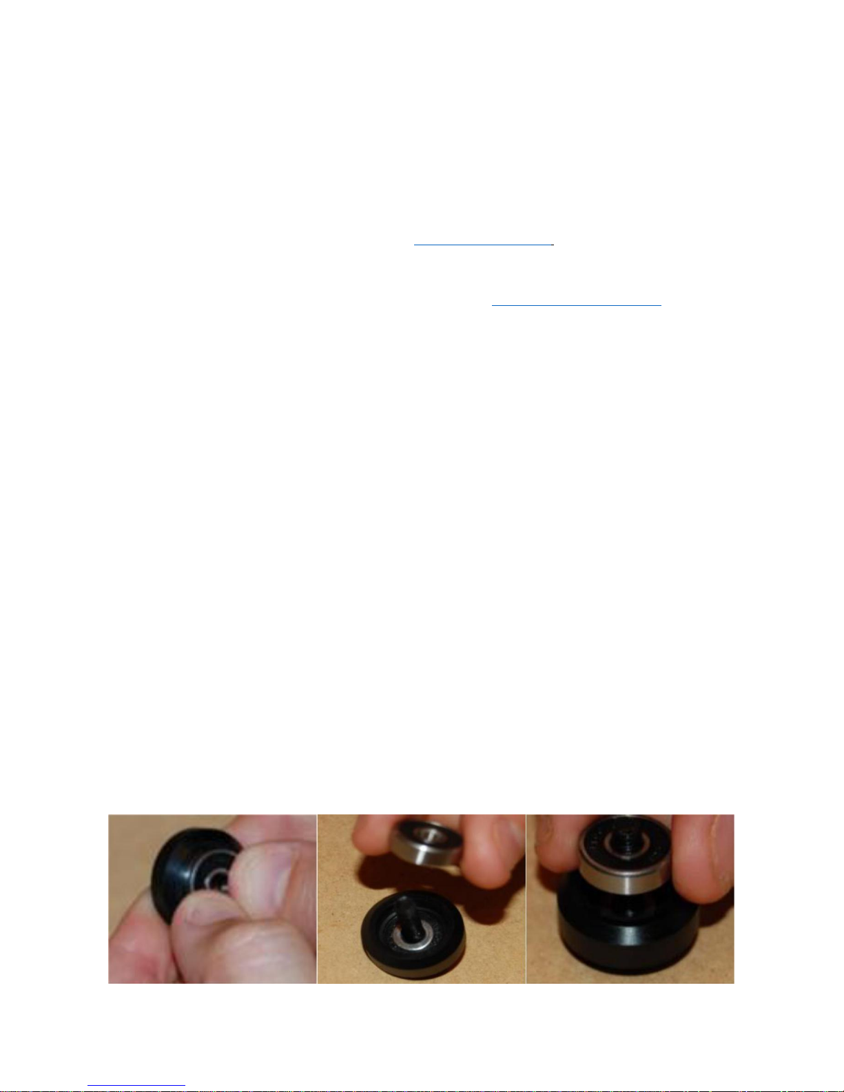
Locate the (12) V Wheel Kits included with the basic kit. NOTE: Those that ordered the rigidity
kit upgrade should assembly the extra (2) V wheels that you have now. Take the wheel body and
snap (1) 625 bearing into one side. Run an M5 bolt through the inside hole of that same bearing,
then flip it over in your hand. Slide an M5 washer that comes in the V Wheel Kit down over the
threads of the M5 Bolt. This helps properly locate the washer on the race of the bearing. DO
NOT FORGET TO INSTALL THIS WASHER BETWEEN THE TWO BEARINGS, OR THE V WHEEL WILL NOT
SPIN WHEN TIGHTENED AND WILL BE VERY HARD TO GET BACK APART. While leaving the bolt in,
snap another 625 bearing into the wheel. It may take some effort as sometimes it’s a pretty tight
fit. Set the assembled V Wheel Kits to the side for use in the next steps.
Page 3 of 35

Y AXIS STAGE ASSEMBLY
Locate the Y Axis Bearing plates and (8) of the V wheels that you assembled in the last step.
Grab one of the V wheels and one of the Y Axis
Bearing Plates. Install an M5 bolt through one of
the holes indicated in the picture to the right.
Now install a non-adjustable 6.35mm (quarter inch) spacer on the opposite side of the plate,
sliding it over the threads of the bolt. Install an assembled V Wheel onto the threads of the bolt,
then tighten it down using an M5 nylock nut.
Using an Allen wrench or Phillips screwdriver
(depending on if your kit came with allen or phillips
head M5 screws) and 8mm socket, get these snug
now. Don’t torque too much, just a bit of tension is
fine. If you are straining as you tighten, it is FAR too
tight! The wheel should still turn fairly freely once
tightened. If it’s really hard to spin, back off the nut
a tad. Install another V wheel the same way in the
other hole indicated by the arrow.
Now, take an eccentric spacer and put it in one
of the holes opposite those installed that you just
installed. Spin the eccentric spacer in that hole
and observe how the bolt hole in the spacer gets
closer then farther away from the V wheel kits
that you already installed. This will allow you to
snug up the bearings to the V rail after installing
them. Leave the eccentric spacer in its loosest position (bolt hole farthest away from the other
bearings). Now run an M5 socket head bolt through the plate, then the spacer, then install a V
wheel and loosely install an M5 nylock nut. You should end up with the bolt head, then Y Axis
Bearing Plate, then eccentric spacer, the V wheel, then an M5 nylon nut. Do NOT tighten these
very much yet because you will need to be able to spin the spacer soon. Install another
eccentric spacer and V wheel in the other hole just like you did this one.
Repeat these steps to install the V wheels on the other Y Axis Bearing Plate. Keep the assembled
Y Axes Bearing Plates nearby.
Locate both 2020 V rails as well as the front frame piece (long rectangular piece with four holes in
the middle). Notice the small half circle notch at the bottom of this piece. If that notch is at the
bottom left, then you are looking at the front side of the piece. Check out the middle picture on
page 22 to see the correct orientation of this piece when installed.
Page 4 of 35
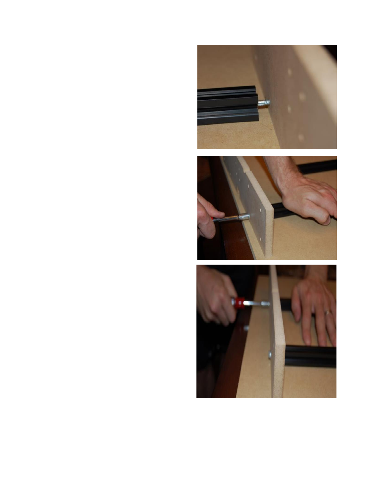
Using a flat surface, flip the front MDF frame part
upside down and slide an M5 washer on a selfdrilling screw, then start threading the selfdrilling screw into the appropriate hole of the
MDF frame. Once the head of the screw starts to
poke through the other side, slide the center hole
of the 2020 V rail over the screw point.
Press the V rail against the MDF frame, while
holding it down against the flat surface and keep
driving the screw in. Get it snug, but not super
tight. The machine is designed for the top of the
Y Axis V Rails to flush up to the top of the front
frame piece, so flipping it upside down and
using a flat surface will help flush things up.
You should now have both 2020 V Rails screwed
into the front frame piece. Grab one of the Y
Axis Bearing Plates that you already installed the
V wheel bearings on, and slide it onto the right
V rail. Notice that the Y Axis Bearing Plate has
one side that is longer than the other. The
longer side (the one with four total holes, two of
which have eccentric spacers in them), will go
towards the outside. The bolts on the outside
wheels should be loose enough to allow you to
spin the eccentric spacer with a 10mm wrench,
but not “sloppy loose.” Now spin the eccentric
spacer on one of the v wheels so as to tighten
the V wheel into the V channel in the V rail. It’s
probably already almost tight enough.
Page 5 of 35

Tighten both eccentric spacers an equal amount. These wheels will need very little tightening with
the spacer. TAKE VERY CAREFUL NOTE OF THE FOLLOWING, OR YOU WILL CAUSE YOURSELF A
PROBLEM LATER. DO NOT OVERTIGTHEN THE V WHEELS INTO THE V RAIL. THE V WHEELS ARE
MADE OF A VERY TOUGH PLASTIC (ACETAL OR POLYCARBONTE), BUT THEY WILL DEFORM IF
TIGTHENED TOO MUCH, LEAVING YOU WITH
CLUNKY MOTION WHICH WILL RESULT IN POOR
CUTS. SET THE TENSION SUCH THAT YOU CAN
DRIVE THE ENTIRE Y AXIS BEARING PLATE BY
ROLLING A WHEEL WITH YOUR FINGER BUT LOOSE
ENOUGH THAT THE WHEEL WILL SLIP IN THE RAIL
IF YOU LIGHTLY HOLD THE Y AXIS BEARING PLATE
WHILE YOU SPIN A WHEEL. Slide the bearing plate
back and forth to make sure that it glides
smoothly along the rail. If the wheels are too
tight, loosen the spacer a bit and recheck. Note
that, if over time, you find the wheels develop a
flat spot over time from being too tight, you can
loosen the wheel and it will move back to its
circular shape in a few hours.
Now find the back frame piece (the other long
rectangular piece). Slide the Y Axis Bearing Plates
that you just installed onto the rails all the way to
the Front Frame Piece. Hold the Back Frame Piece
upside down and cantilever the Front Frame Piece
and Y Axis Bearing Plates over the edge of your
table so the other side of the rail flushes up to the
Back Frame Piece. Slide an M5 washer onto a
self-drilling screw and place it in the appropriate hole. If it’s snug in that hole, continue to turn it
through the Back Frame Piece until the drill point of the screw is sticking out. Slide the tip of that
screw into the center tap how of the V Rail. Do the same with the other rail. Grab the rail firmly
with your hand as you tighten. The torque of threading the screw tends to cause the rail to spin,
which you want to prevent. As you start to get good bite into the V rail with both screws, you can
set this assembly in its natural position (as it will be on the completed machine) in order to make
Page 6 of 35

tightening and alignment easier. Remember that the top frame piece should flush up to the top
of the V rail. Make sure it ends up that way when you finish tightening the screws. Now confirm
that the rails are close to parallel. This shouldn’t be a problem, but the holes sometimes allow
for a bit of a free fit for the screws, so you will want to check this and adjust accordingly. If you
have a square, you can check that the rail and the frame pieces are perpendicular, but this
usually just arises naturally from how it all goes together. Flip them back over and sit it down on
a known flat surface. If there is a bit of rock back and forth, you need to slightly loosen one or
more of the self-drilling screws
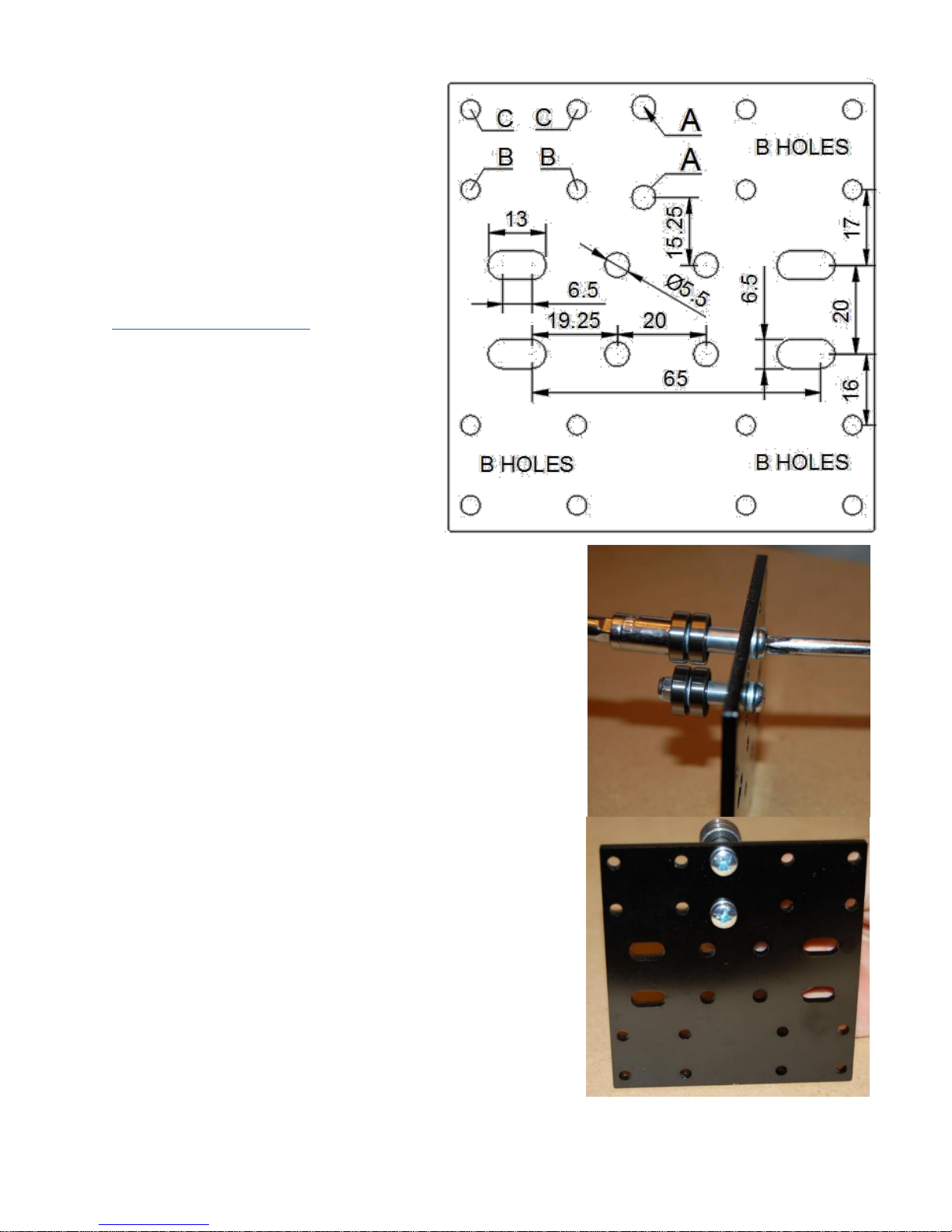
Keep this close and find the MDF bed. Lay the bed top down so you can see all of the pockets
that look like this:
Page 7 of 35
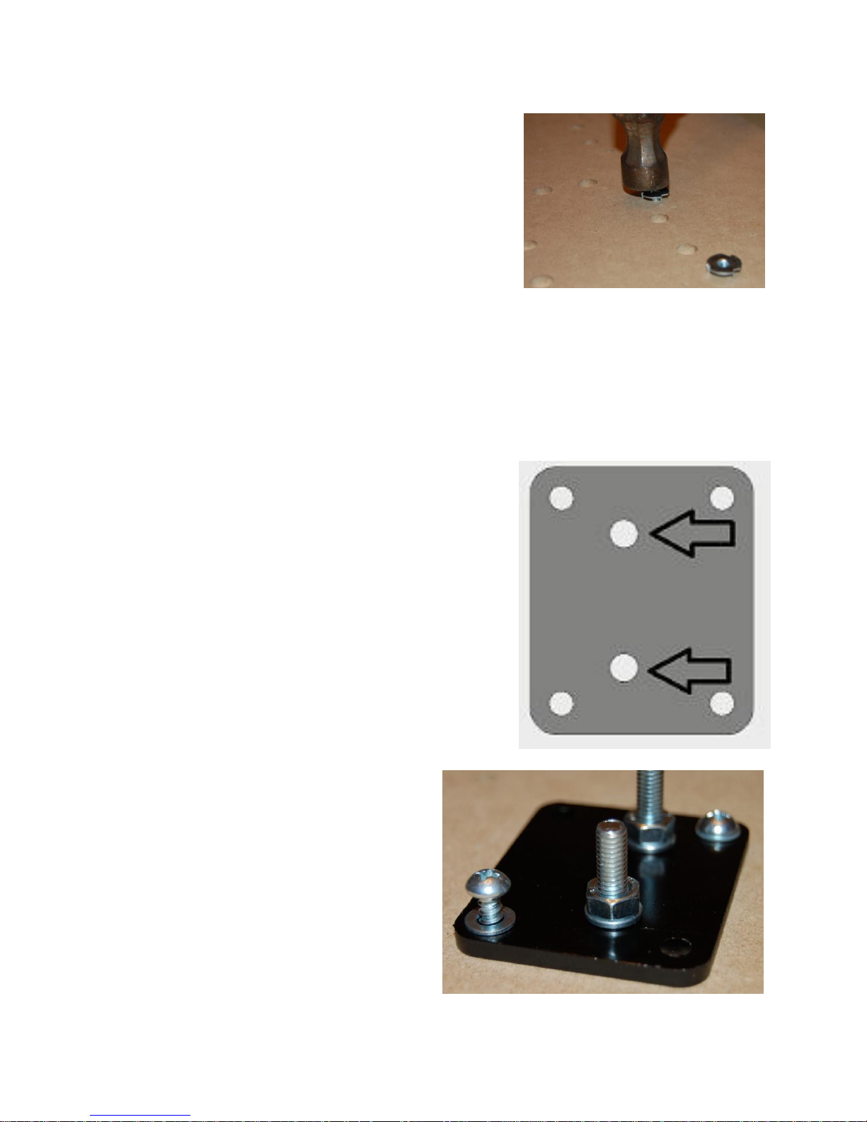
Flip the bed back over so the Y Axis Assembly is upside
down. Using your hammer, tap the T-nuts into the 16
holes labelled “A” in the above diagram.
Now find the Y Axis Belt Anchor Plate. Slide an M6 washer onto an M6x25 screw then put the
bolt through the plate in the orientation shown below. If you were looking down at the plate
in this orientation, you should see the bolt heads. In this orientation, the M6 screw needs to
go through an M6 flat washer, through the plate, then through a split-lock washer, then
secured with an M6 nut. Get a final tighten on the nuts now. These don’t screw to anything
else, they just serve as studs to anchor the belt.
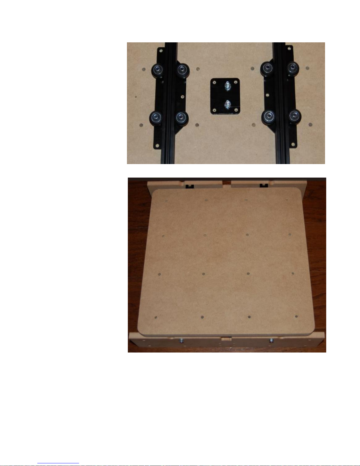
Put the Y Belt Anchor Plate against the bed so the heads of
the M6 bolts are laying inside the holes marked “D” in the
center of the above picture. Line up the holes on the
corners of the Y Belt Anchor Plate with the holes marked
“B” that form a square around the holes marked “D.” Slide
an M5 washer onto a 5/8” wood screw, then screw it into
the bed in order to secure the Anchor Plate to the bed. DO
NOT OVER-TORQUE THESE OR THE SCREW WILL RIP THE
HOLE OUT. Pick one corner to start, and leave the screw
a little loose. Line up the hole on the opposite corner,
then screw it in. Put a final torque on the four wood
screws once you have them all in. A contributor to this
kit’s development has suggested inserting the screw
fully, pulling it out, putting a couple drops of
superglue (not included) in the hole, and
immediately rethreading the screw in the
hole. This is intended to prevent the screws
from vibrating loose over time.
You will now install the Bed onto the Y Axis
Assembly. Orient the bed so that it holes are
facing up, like in the diagram above. The holes
designated as “C” above are recesses for the
bolt heads of the V Wheel Kit bolts that are
on the Y Axis Bearing plate. Flip the Y Axis
Page 8 of 35
Assembly upside down and
lay it onto the bed so that
these bolt heads lay in
those recesses. Looking at
the bed in the orientation
above, the Front Frame
Piece should be towards the
top. Notice that each Y Axis
Bearing Plate has three
small holes left. Line these
holes in the plate up with
the small pilot holes. Slide
an M5 washer onto the
wood screws, then begin to
thread it into the holes. Do
not tighten the wood
screws down until you get
all the screws in both
bearing plates (six total,
three in each plate). Check
as you tighten the screws
down that the bed flushes up
to the front of back Frame
Piece. It should not be
canted or twisted. After you
finish mounting the bed, flip
the Y axis assembly back
over and slide it back and
forth to ensure that the
motion is smooth. If not,
either the eccentric spacers
are too tight or the bearing
plates were a bit cocked
relative to one another
when you torqued them down tight.
Z AXIS BEARING PLATE ASSEMBLY
We will now assemble the Z Axis plate. This is the plate that will carry your router or spindle
up and down. The diagram to the below shows the FRONT of the Z Axis plate. Notice that the
Page 9 of 35
position of the holes marked (A) being
slightly left of center will help you orient
the plate properly. The Z Axis plate was
designed to accommodate some of the
most popular choices in hobby CNC.
Hopefully, you’ve already selected the
router/spindle and mount combination
that you wish to use. See
www.millrightcnc.com/FAQ for more info
on the compatible spindles and mounts if
you don’t already have one. We have also
included some dimensional information
about the mounting holes for those
interested in making their own mount or
confirming fitment of available mounts.
The hardware used in each hole is as
follows:
Each one of these will be installed such that the head of the
screw or bolt is visible as you view the Z Axis Bearing Plate in
this orientation.
A: M5x30 - Belt Idler
B: M4x10 – Bearing Block
C: M4x14 – Bearing Block / Spring Stud Bracket
We will first assemble the idler bearings on your Z Axis plate.
Each idler is made of two 625 bearings, so go ahead and grab
four 625 bearings, two M5x30 bolts, 4 M5 flat washers, two
10mm long aluminum spacers, and two M5 Nylock nuts.
TAKE NOTE THAT THE ALUMINUM SPACERS USED HERE ARE
LONGER THAN THE ALUMINUM SPACERS USED WITH THE
NON-ADJUSTABLE V WHEELS. Slide an M5 washer onto the
M5x30 bolt and put the bolt through one of the holes
labelled with (A) in the above diagram. You should insert the
bolt through the hole when looking at the Z Axis Plate as
shown in the diagram.
Be careful not to build things on the wrong side. Now, slide
the 10mm aluminum spacer on the bolt threads and butt it
up against the back side of the Z Axis Plate. Put on a 625
Page 10 of 35

bearing, followed by an M5 washer, and then
another 625 bearing. DON’T FORGET THE
WASHER BETWEEN THE TWO BEARINGS OR THEY
WON’T SPIN. Secure all of this with an M5 Nylock
nut. You want to get this good and snug, but
don’t go crazy. Looking down at the Z Axis plate in
the orientation shown in the diagram above, you
should have the head of the M5 bolt, an M5
washer, the Z Axis Plate, a 10mm aluminum
spacer, a 625 bearing, an M5 washer, another
625 bearing, and a Nylock nut. Install the other
idler this same exact was in the other hole
labelled with letter (A).
Now locate your linear bearing blocks. Notice in
the diagram that the top left of the Z Axis Bearing
Plate has two holes marked (B) and two marked
(C). The other three bearing blocks have all
(B) holes and use M4x10 screws with splitlock
washers. Install these bearing blocks on the Z Axis Bearing plate with M4x10 screws and M4
split-lock washers in the holes marked (B). You should see the heads of the screws when
looking at the Z Axis Bearing Plate in the orientation shown in the diagram above. The bearing
blocks should be on the back side of the plate.
The top left two holes are labelled (C) and will be used to mount the spring stud bracket. Use
M4x14 screws with a split-lock washer to mount the Spring Stud Bracket to the plate. You’ll
screw into the bearing block to secure this. Looking at the Z Axis Bearing Plate in the orientation
shown in the diagram, you should have the screw head, an M4 split-lock washer, the Spring
Stud Bracket, the Z Axis Bearing Plate, then the linear bearing block. Make sure you get the
orientation of this spring stud bracket correct. Slide an M6 flat washer onto the M6x50 screw
then put it in the slot in the Spring Stud Bracket with the screw threads pointing towards the
back of the Z Plate. Secure it with an M6 split-lock washer and an M6 nut. Slide one loop of the
extension spring onto the threads of the
M6x50 screw you just installed.
Sandwich the loop of the spring between
the M6 nut you already have installed
and another M6 nut so that the spring
naturally points to about the 10 o’clock
position. Looking at the Z axis plate in
the orientation shown above, you should
have the head of the M6 screw, a flat
washer, the Spring Stud Bracket, an M6
Page 11 of 35

split-lock washer, an M6 nut, the loop of the spring, and finally another M6 nut. This screw will
also engage the Z axis homing switch, so if you have homing switches you will tweak this position
in the slot later. This spring orientation is very important to make sure the spring folds out of the
way when your machine lifts Z all the way to the top. Keep it at 10 o’clock.
Install the router or spindle mount that you have selected now. THE MOUNT SHOULD BE ON THE
FRONT SIDE OF THE PLATE. We recommend mounting into the bottom row of mount holes if
your mount gives you the option of mounting in the top or bottom row. Some mounts, such as
the 52mm spindle mount, use both the top and bottom rows to mount. Install only the mount
right now. Wait to install the router or spindle
until later. These assembly instructions do not
show a mount being installed.
Set aside the assembled Z Axis Bearing Plate
for now.
X AXIS STAGE ASSEMBLY
Let’s get started on the X Axis Assembly. You are
making some real progress here!
Locate the X Axis Bearing Plate. Use the
following diagram of the FRONT SIDE of the X
Axis Bearing Plate, to help you place the parts
and fasteners on the plate:
TAKE NOTE THAT THE LETTER LABELS HERE
HAVE NOTHING TO DO WITH THE LETTER LABELS
OF THE BED DIAGRAM. If there is an (H) below, it
means that you will see the head of the bolt or
screw when looking at the X Axis Bearing plate in
this orientation. If there is a (T), it means that
the threaded side of the bolt will be pointing
towards you when looking at the X Axis Bearing
plate in this orientation. Be careful here, it’s easy
to install things on the wrong side if you aren’t
paying close attention.
Page 12 of 35

A: M5x25 - V Wheel (H)
B: M6x25 - Belt Anchor (T)
C: M5x30 - Belt Idler (T)
D: M3x8 - Motor Bolt (H)
E: M6x40 - X Homing Switch Stud (H)
F: M3x20 – Z Homing Switch (H)
G: M5x16 - Rod Support (H)
Let’s go in letter order to get the X Axis Bearing
plate built.
Grab (4) assembled V Wheels and (2) eccentric
spacers, or (6) assembled V Wheels and (3) eccentric
spacers if you ordered the rigidity upgrade. If you did
not order the extra two wheels, make sure you install
them in the outer four holes and leave the two inner
holes empty. Start with the bottom row of holes
marked (A). Install V wheels there, such that the
wheels are on the back side of the plate as you are
looking at it in the diagram. Looking at the X Axis
Bearing plate in the orientation shown in the above
diagram, you will have the M5 fastener head, then the
X Axis Bearing plate, then a 6.35mm (1/4”) aluminum
spacer, then an assembled V Wheel, then secured with
an M5 nylock nut. The top (A) holes are going to be
the same, except that you’ll have eccentric spacers
instead of the fixed aluminum spacers. Remember that
the eccentric spacers are used to tighten the V Wheels
to the rail, so install them now in their loosest position
and leave the bolts loose enough that you can adjust
them once you have the bearings riding on the V Rail
extrusion (you’ll install it on the rail later). DON’T
FORGET TO TIGTHEN THEM THEN.
Now you’ll install the M6x25 screws that are used as
belt anchors in the holes labeled letter (B). Take special
note of the orientation called for in the table above.
The threaded side of the bolt will be pointing
TOWARDS you when looking down at the front of the X
Axis Bearing Plate. There is one (B) hole at the top left
and one (B) hole at the bottom center. Slide an M6
washer onto an M6x25 bolt, insert it in the top (B) hole
Page 13 of 35

FROM THE BACKSIDE. Slide an M6 split-lock washer onto the bolt, then thread on an M6 nut.
Looking down at the X Axis Bearing Plate in the orientation shown in the above diagram, you
should see the threads pointing at you, an M6 nut, an M6 split-lock washer, the X Axis Bearing
Plate, an M6 flat washer, then the M6 bolt head. Do the same with the hole labelled (B) at the
bottom of the plate. Remember, these bolts should be pointing TOWARDS you.
There is only one hole labeled (C). This bolt will also point towards you when looking at the front of
the X Axis Bearing Plate. You’ll need an M5x30 screw, two M5 washers, two 625 bearings, one M5
Nylock nut, and one 10mm aluminum spacer. BE CAREFUL WHICH SPACER YOU PICK UP HERE. THE V
WHEELS USE A DIFFERENT SPACER (6.35MM). THIS SPACER IS LONGER THAN THOSE. Slide an M5
washer onto the bolt and insert the bolt through hole (C) from the backside. Now slide the 10mm
aluminum spacer onto the threads, followed by a 625 bearing, an M5 washer, another 625 bearing,
and top it off with an M5 Nylock nut. Get this nice and snug, but don’t go crazy. Bolts can bend if
overtightened. As you look down at the plate in the same orientation shown in the diagram, you
should have the Nylock nut, a 625 bearing, an M5 washer, another 625 bearing, the 10mm spacer,
the X Axis Bearing Plate, an M5 washer, then the head of the M5 bolt.
Now grab a NEMA 17 stepper motor so you can install it at the top of the X Axis Bearing Plate. You
will mount it with M3x8 bolts in the four holes labeled (D). Take special note that wires coming out
of the motor should be pointing towards the bottom left when you install the motor. Look at the top
of the diagram. There is a top (D) hole, a right (D) hole, bottom (D) hole, and left
(D) hole. You want the wires on the motor to be sticking out between the left (D) hole and the
bottom (D) hole. Slide an M3 split-lock washer onto an M3x8 button head bolt and install the
motor. Looking down at the X Axis Bearing plate in the orientation shown in the above
diagram, you should see the M3 bolt head, M3 split-lock washer, X Axis Bearing Plate, then the
stepper motor body. The shaft of the stepper motor will be pointing up at you in this
orientation if you are looking down at the X Axis Bearing Plate as shown in the diagram above.
If you purchased the homing switch kit, you will install an M6x40 bolt in the hole labelled (E).
There is only one such hole.
Slide an M6 flat washer onto
the M6x40 bolt, insert the bolt
into hole (E). Secure the bolt
using an M6 split-lock washer
and M6 nut. Looking down at
the X Axis Bearing Plate in the
orientation shown in the above
diagram, you should see the
head of the M6 bolt, then a flat
washer, then the X Axis Bearing
Plate, then an M6 split-lock
washer, then an M6 nut.
Page 14 of 35

If you purchased the homing switch kit, you will install the Z axis
homing switch with M3x20 bolts in the two holes labelled
(F). You’ll need one limit switch, two M3x20 screws, two M3
split-lock washers, two M3 flat washers, and two M3 nuts.
Install the switch in the orientation shown in the picture. Slide
an M3 flat washer onto the M3x20 screw, then slide the bolt
through hole (F) and through the homing switch bolt hole.
Secure it with an M3 split-lock washer and M3 nut. Do this
with both holes. Snug it up enough to flatten the split-lock
washers, but DO NOT OVERTIGHTEN OR YOU WILL DESTROY
THE SWITCH.
Locate (4) linear rod supports. Look at the rod supports and
notice that there is an Allen head screw that tensions the rod
support to the linear rod. Make sure that the heads of these
adjustment screws are oriented to the outside when you install
them. Place the first rod support over the bottom left two (G)
holes. Install it with an M5x16 machine screw and secure it
with an M5 flat washer, and M5 Nylock nut on the backside of
the X Axis Bearing Plate. Leave these just slightly loose. Looking
down at the plate in the orientation shown in the diagram
above, you should have an M5 Machine screw going through
the rod support, then going through the X Axis
Bearing Plate hole (G), secured on the back side by an M5 washer and M5 Nylock nut. Install the
bottom right rod support now. Also leave these a bit loose. We will come back to the X Axis
Bearing Plate in a minute to install the top two rod supports in the remaining (G) holes.
Page 15 of 35

Grab your Z Axis Bearing Plate and your
two 8mm diameter chromed linear rods.
CAREFULLY slide the rods through the
openings in the linear bearing blocks. If
the rods seem hard to push through the
second bearing, you need to loosen the
screws fastening the linear bearing blocks
to the Z Axis Bearing Plate. Put tension
back on the screws that mount the linear
bearing blocks once you get the rods in. If
try to force these in or if you are not careful
sliding the rods through the bearing blocks,
you could push some of the ball bearings
out of the bearing blocks. If you accidently
push a couple out it’s not the end of the
world, however.
Now, lay the Z Axis Bearing Plate (with
the linear rods still in it, careful not to let
them slide out!) next to the X Axis Bearing
Plate. Study the orientations of these
plates shown in the above diagrams. We
should end up with the Z Plate in front of
the X Plate with these same orientations
shown. Let’s do that now.
Work with the X Axis Bearing Plate laying
on the table, face up. Keeping in mind the
required orientation of the plates, slide in
the bottom of the rods that are in the Z
axis linear bearings into the bottom rod
supports that you’ve already installed on
the X Axis Bearing Plate. As soon as you slide the bottom of the linear rods into the bottom rod
supports, slide the top two rod supports onto the top of the rod. On just the bottom rod
supports, tension the Allen head bolt that clamps the rod support to the rod. Now install M5x16
machine screws into the mounting holes for the top rod supports, through the top (G) holes on
the X Axis Bearing Plate, and begin to snug them up using an M5 flat washer and M5 Nylock nut.
Now run the left most M5 screw through the free loop of the spring, and snug it down. Make
sure the rods are parallel and the two rod supports are even in terms of their position on the X
Axis Bearing Plate before you put a final torque on these mounting and tension screws.
Page 16 of 35

You should now have your assembled Z Axis
Bearing Plate mounted to your X Axis Bearing
Plate. This is the X & Z Axis Bearing Plate
Assembly. Before you go any further, check
the diagrams again. Did you get the
orientation right?
Congrats on the progress!
We will now route the Z Axis Belt. Fair warning:
Belt installation is one of the trickier parts of the
build for some people, so take your time, read
carefully, and relax.
See the diagram to the right which shows the Z
Plate in front of the X Plate with most of the
unrelated holes removed for clarity. The red
circles are the idler pulleys mounted on the Z
Axis Bearing plate. The blue circles are on the X
Axis Bearing Plate. The top left blue circle is the
top belt anchor point. The blue circle with the
“M” in the middle is the motor pulley. The
smaller blue circle at the bottom is the bottom
belt anchor. The blue circle marked with an “I”
in the middle is an idler pulley.
Install the pulley on the motor shaft. Look
down this assembly from the top so you can
position the motor pulley’s teeth in line with
the idler pulleys. One of the set screws must be
set against the flat of the motor.
The kit came with three sections of belt. Grab the
SHORTEST SECTION OF BELT (900mm) and anchor
it to the threads of the M6 bolt with a zip tie. Loop
it EXACTLY as shown in the diagram and make sure
the teeth of the belt are meshed together. If you
don’t loop it as shown here and zip it together
with the toothed side of the belt, the belt will get
routed backwards. You must zip tie it at a point
that is in line with the pulleys, or the belt will run
off the pulleys. Run the belt around the bottom Z
Axis Bearing Plate Idler Pulley (indicated
Page 17 of 35

by the bottom red circle in the belt route diagram). It is easiest to do this if the Z plate is all the
way at the bottom. Then guide the belt onto the pulley using your index finger. The teeth
should be against the pulley bearings on this one. Loop it down around the bottom idler pulley,
indicated by the blue circle with an “I” in the center.
Page 18 of 35

Now run it up the middle to loop around the motor pulley, then around the top Z Axis Bearing
Plate Idler Pulley, indicated by the top red circle. The toothed side of the belt should mesh with
the teeth on the motor pulley and the backside of the belt will run on the top Z Axis Idler Pulley.
Keep some tension on this belt to make sure it doesn’t slip off a pulley. Run the belt around the
top anchor point and secure it with a zip tie. The teeth should mesh together. You’ll want at
least 6 or 7 pounds of tension on the belt. Floppy belts are no good. Get some tension.
Now that you have the belt fully anchored, move the Z Axis Bearing Plate up and down to make
sure that the belt isn’t slipping off any of the pulleys. If it is, one or both of the anchor points is
misaligned, the motor pulley is misaligned, a screw is looser, or you have too much tension. If
you used the proper spacers when you assembled the bearing plates (10 mm aluminum spacers),
the bearings on the pulleys will be aligned on both plates.
Now locate the left frame piece as well as the 2040 V Rail Extrusion. Slide an M5 washer onto a
self-drilling screw and put the
screw through the top hole.
Slide the screw point into the
top tap hole of the 2040 V Rail
Extrusion and begin threading it
in. It’s best to tilt the frame
piece back with the opposite
end of the V Rail Extrusion on
the table or floor as you thread
it in. Get a few threads turned
into the top hole then get the
second hole started with
another M5 washer and self-
drilling screw. You’ll want to
end up with the top of the
frame flushed up to the top of
the V Rail Extrusion. Take
special care that the rail isn’t
cocked in any way, or your
router (or spindle) will never be
plum. Keeping this in mind, get
a final torque on the top and
bottom self-drilling screws.
Page 19 of 35

Now slide the X & Z Axis Bearing Plate Assembly onto the
other side of the V Rail extrusion. Continue to support the
V Rail Extrusion and place the right frame piece in position.
Slide an M5 washer onto a self-drilling screw then place
the screw into the top hole. Get a few threads turned into
the top center tap hole of the 2040 V Rail Extrusion then
get the bottom hole started with another M5 washer and
self-drilling screw. Just like with the other side, make sure
that the top of the V Rail Extrusion flushes up to the top of
the right frame piece. Once you are confident that the rail
isn’t canted and everything is flush, put a final torque on
the self-drilling screws on both sides of the frame.
X&Z AXIS ASSEMBLY CONNECTION TO Y AXIS
ASSEMBLY
Take your Y Axis Assembly and set it down so that the
moving bed is facing upward. We will now put the frame
pieces together. Take special care to get the orientation
correct. The front frame piece has four holes below the
cutout for the belt for the motor mount, while the back
frame piece only has one hole in this area. The right frame
piece has four holes for a motor mount under the cutout
for the belt, while the left frame piece only has one hole in
this area. Grab your completed X&Z Axis Assembly which
has the left and right frame pieces attached and place it
into position within the Y axis assembly which has the front
and back frame pieces. Sometimes this fit is a little snug,
so you may have to slightly pry at the sides of the front
and rear frame pieces to get the left and right frame pieces
to slide in. Move things around a bit in order to flush up
the edges and square everything up. Don’t worry if every
corner isn’t perfectly flush yet where the left and right
frame pieces meet the front and back frame pieces. You’ll
get it locked down right in a minute.
Page 20 of 35

Each corner is secured and supported by two cast
aluminum corner brackets. Start putting the brackets
on one corner at the time, with the bottom bracket
first. To complete this step, you’ll need (8) corner
brackets, (16) M5x25 machine screws, (16) M5
washers, and (16) regular M5 nuts. NOTE: Starting in
January 2017, some kits shipped with slots in the
MDF frame pieces to allow clearance for the tabs on
the back of the corner bracket. If your kit is like this,
be sure to use the 8 corner brackets that still have
tabs on the back for connecting the frame pieces and
leave the 2 that have tabs ground off for the idler
bearing mounts.
Slide an M5 washer onto an M5x25 screw and put it
through one of the bottom holes in the frame so
that the threads are sticking through the other side.
Slide the corner bracket over the threads and into
the corner. Hold that in place while you finger
tighten a nut onto the threads. It will be easier for
you to just get the nuts started on the threads then
turn the screw head with a screw driver. Don’t
tighten anything up yet. Now install the second
screw on this corner bracket the same way.
Move onto the top corner bracket for this corner and
install it the same way. As you put the second screw
in the bracket, you may have to first press the nut
against the inside of the bracket and then begin to
screw it in, in order to get clearance. Do all four
corners now, leaving it all a bit loose. Confirm that
the frame pieces are squared up, then tighten all the
corner bracket screws. You can use needle nose
pliers to hold the M5 nut in the corner bracket at you
tighten the screw head. You might also be able to
use a deep 8mm socket and ratchet.
Page 21 of 35

X and Y AXIS MOTOR MOUNTING and BELT ROUTING
The Y Axis motor, belt, and belt idler will be
installed first.
Grab a NEMA 17 mount and NEMA 17 motor.
Install the motor mount onto the front frame. Put
an M4x20 bolt through the motor mount slot,
then the front of the frame, and secure it to the
back side with an M4 flat washer and M4 Nylock
nut. You’ll want to mount it a few millimeters
above the surface of the table that the machine is
sitting on. Don’t sweat an exact measurement,
you just want the bottom of that motor fairly
close to the surface of the table. Secure the
mount with four M4x20 screws total. MAKE SURE
THAT THE MOUNT IS LEVEL. YOU DON’T WANT TO
END UP WITH A CANTED MOTOR. Now install the
NEMA 17 motor with (4) M3x8 button cap bolts
and M3 split-lock washers. As you are looking at
the front frame piece, the wires coming out of the
motor should be oriented to the left.
Now lay the machine down on the left frame piece,
being careful not to allow the X Axis Bearing Plate
to slam into the frame as you tilt it over. Grab the
longest section of GT2 belt (1200mm) and use it to
get a feel for exactly where the motor pulley needs
to be positioned on the shaft. The belt is going to
get zip tied to the two M6 bolts that are sticking out
of the center of the bottom of the bed. Just hold
the belt in place with your fingers on the belt
threads of the stud in the Y Axis Anchor Plate
nearest the motor and wrap the belt around the
motor shaft. Take note of how you can position
everything so that the belt is parallel with the
moving bed. You don’t want it binding up because
the anchor point and the motor pulley are
misaligned. Once you take a good mental picture of
how to position the anchor point and the pulley, go
ahead and zip tie the belt to the bolt such that the
teeth of the belt
Page 22 of 35

mesh together. Only leave about an inch of extra belt wrapped around here or you could run out
on the other side. See the picture. If you are looking at this with the left frame piece laid flat, you
should just have that front most anchor point zip tied on now.
Now slide your GT2 motor pulley onto the motor shaft. If it won’t slide on there, make sure a
set screw isn’t already screwed in and is catching on the shaft. There are two set screws on the
motor pulley. Set the set screws at a point where the
belt is going to run on the pulley without binding up.
ONE OF THE SET SCREWS ABSOLUTELY MUST BE SET
AGAINST THE FLAT PART OF THE MOTOR SHAFT.
Now let’s build two idler pulley assemblies; one for this
belt and one for the X Axis belt. For each pulley
assembly, you’ll need (1) cast aluminum corner
bracket, (1) M5x25 machine screw, (3) M5 washers, (2)
M6 washers, and (1) M5 Nylock nut. The preceding
figures don’t include the mounting hardware, just what
is needed to build the idler itself. Slide the following
pieces onto the M5x25 machine screw IN THIS EXACT
ORDER. First slide on a 625 bearing, then an M5
washer, another 625 bearing, another M5 washer, then
an M6 washer. Now insert that screw (with all of those
things still slid onto the screw) into one of the slots of
the corner bracket such that the bearings are on the
outside of that bracket. Now slide on an M6 washer,
then an M5 washer, and secure everything with an M5
Nylock nut. An 8mm socket is going to be helpful for
tightening up that nut. You will want to secure this
towards the back of the bracket, a bit away from the
inside corner. Get this good and snug, but don’t
overtighten. Repeat this process to build the second
idler pulley assembly. Make sure the bearings aren’t
mounted crooked or the belt will wander wildly.
Now install one idler assembly on the back frame piece
in the hole that is under the opening for the belt. Slide an
M6 washer onto an M6x25 machine screw then put the
screw into the hole under the opening for the belt from
the INSIDE. Now slide the slot of the corner bracket over
the threads, from the outside. Now slide on an M6 splitlock washer and an M6 nut. Before you tighten this all
the way, get a good feel for exactly
Page 23 of 35

where it needs to be positioned up and down in the slot so that the belt is properly aligned. Note
that this corner bracket will have a little wiggle room left and right before it’s tightened as well,
so make sure the belt isn’t going to scrub the walls of the opening either when you look for the
perfect place to tighten it down. Now wrap the belt around the other anchor. Get creative about
keeping the bed stationary as you pull the belt into tension. Your needle nose pliers might come
in handy here to grab the belt and pull it tight after you loop it around the stud coming out of the
Anchor Plate. Use a zip tie just as you did on the other side, with the teeth of the belt
interlocking. Get the belt snug, but not too tight. Six or seven pounds of pull tension. Remember:
Floppy belts are bad! Now move bed back and forth with your hand. THE BELT MAY BIND OR SLIP
UPWARDS OFF THE PULLEY, BUT THERE IS A FIX FOR THIS. If the belt tries to run off the idler, the
axle of the idler pulley (the M5x25 machine screw) could be a little canted. Loosen the screw and
rotate it a bit to try make it flush. You also need to make sure the back frame piece is flushed up
to the side frame pieces. If it’s canted back or forward
(IE, looking at corner where side frame pieces and
back frame meet there would be an air gap top or
bottom) it can cause the belt to wander off the
pulley.
Snip excess length from the belt, but leave enough to
work with in case you ever have to do this again.
Now install the NEMA 17 motor mount and NEMA 17
motor on the right frame piece using the same
hardware that you used for mounting the Y Axis
motor on the front frame pieces.
Zip tie the remaining belt section (1040mm) to the
bottom right vertical slot in the X Axis Bearing Plate.
There are a couple different configurations that you
can use to secure the belt, but this is the easiest. Be
aware where you put the head of the zip tie. Zip it so
that the head won’t catch on the right frame piece as
you move the X Axis Bearing Plate to the extreme
end of travel or else you will lose a few millimeters of
travel. Install the motor pulley on the motor shaft,
remembering that it should line up with the belt
without causing any binding. Ensure that one of the set screws is set against the flat part of
the motor shaft.
Now you will install the other Idler Pulley Assembly that you built in a previous step on the left
frame piece. Notice that the mounting hole is counter-bored on the interior side of the Left
Frame. You should mount the head of the M5x25 machine screw into this recess with an M5
washer. Slide the slot of the other Idler Pulley Assembly over the threads, followed by an M6
Page 24 of 35

split-lock washer, an M5 flat washer, and a regular M5 nut. You will need your needle nose pliers
to hold the nut as you tighten up the screw, but wait until you get the belt routed to tighten it up
all the way so you can wiggle this pulley around to the right position.
Route the belt from the bottom right anchor
point, around the motor pulley, then pull it behind
the X Axis Bearing Plate, around the Idler Pulley
Assembly, and push the end through the
outermost slot on the bottom left of the X Axis
Bearing Plate. Remember to tighten the mounting
screw for the Idler Pulley Assembly once you
know it’s lined up with the belt. Run the end of
the belt through the front side of the bottom left
vertical slot. Have your zip tie ready, and tension
this by holding the belt in
place as your pull it in the same direction the belt was already going. If you fold it back over
itself now and try to pull it tight, you won’t get any tension. Get tension, hold it in place, then
fold it back to mesh the teeth together. Once secured, slide the X Axis Bearing Plate back and
forth by hand a bit. If the belt tries to run up or down off the idler, follow the same procedure of
loosening and tightening fasteners you used to solve this problem on the Y Axis Belt.
Good job on the progress! If you ordered the Homing Switches or the Rigidity Upgrade, continue
below. If not, skip to the CONTROLLER MOUNTING AND SOFTWARE CONFIGURATION section.
HOMING SWITCH INSTALLATION (only if
you ordered this upgrade)
You should have already installed the Z homing
switch when you assembled the X Axis Bearing Plate.
Start by affixing the X and Y homing switches to the
Homing Switch Plates. For each one, you will need (1)
Homing Switch Plate, (1) Homing Switch, (2) M3x20
Page 25 of 35

machine screws, (2) M3 flat washers, (2) M3 splitlock washers, and (2) M3 nuts. The Y axis switch
assembly will be built in the orientation shown in
the picture to the right. The X switch will have the
“L” opposite. See the middle picture on the next
page for that switch orientation. Slide an M3 flat
washer on the screw, the put it through the plate
and the switch, then secure it with an M3 splitlock washer and nut.
Now put an M5 “drop in T nut” into the Left Y Rail,
towards the Front Frame. Use an M5x12 screw to
install the plate onto the T nut, with a half inch
washer sandwiched between the V rail and the
Homing Switch Plate as shown. You will have the
head of the screw, an M5 washer, followed by the
Homing Switch Plate, the half inch washer, then
the T nut that is embedded into the V Rail. Slide
the bed back and forth a bit and make sure that
the M5 Nylock nut that is on the V wheel doesn’t
catch the head of the M3 screw on the Homing
Switch Plate. If it does, just loosen the Homing
Switch Plate from where you just tightened it to
the T nut and cant it clockwise a tiny bit (there is a
little wiggle room). You can easily get a millimeter
or so of clearance this way. See the picture to the
right.
It’s not shown in this pic,
but you MUST put an M5
washer between the head
of this M5x12 screw and
the switch plate or the
screw will bottom out and
you will never get the
plate tightened down
You’ll now install the stud that engages this
switch in the remaining pilot hole in the bed. For
reference, this is the leftmost “B” hole in the
diagram of the bed on a page 7. Your homing
switch kit will include a long, approximately 1.95”
aluminum spacer. Slide this spacer over the 2.50”
wood screw and insert the screw into the hole.
Once screwed in (don’t overtighten!), it will
engage the switch as the bed moves towards the
front. Loosen the screw on the Homing Switch Plate and slide the T nut forward or back in the
rail so the engagement stud you just screwed in activates the switch about a millimeter or two
before the V wheels hit the front frame piece.
Page 26 of 35

Now let’s move onto the X Axis Switch. Put an M5
“drop in T nut” into the backside of the X Axis Rail,
close to the Right Frame Piece, as shown in the picture
to the right. Now install the X Axis Homing Switch just
like you did the Y Axis Homing switch. Take a look at
the picture to the right and ensure that yours looks like
this. Just like with the other switch, you need to loosen
the M5x8 screw that mounts the Homing Switch Plate
to the rail and slide the drop in T nut left or right so
that the stud protruding out of the back of the X Axis
bearing Plate engages the switch.
The homing switch kit comes with six connectors and
six lengths of wire. Three of the wires have a small 2
terminal connector for the controller end. The open
end of these must have the connectors crimped or
soldered onto the wires.
When you connect these, one connector should be
on the “COMM” terminal and the other should be on
the “NO” (stands for “normally open”) terminal of the
switch. Plug the other end into the stepper driver
shield. You’ll notice the right side of the driver board
has a section for “End Stops.” Plug Z into “Z+”, Y into
“Y+”, and X into “X+”. When looking at the stepper
driver shield, the RED wire goes to the LEFT. Refer to
the supplemental homing instructions for more specifics
on the wiring.
FRAME RIGIDITY UPGRADE INSTALLATION (only
if you ordered this upgrade)
The Rigidity Upgrade includes two extra V Wheels for
the X Axis Bearing Plate as well as three threaded rods
to strengthen the frame. You should have installed the
two extra V Wheels on the X Axis Bearing Plate when
you built that plate. You will install the three threaded
rods to strengthen the frame now. Although the rods
are small, they are actually quite strong along the axis
of the rod when brought into tension.
You MUST put an M5 washer between the head of this
M5x12 screw and the switch plate or the screw will bottom
out and you will never get the plate tightened down
Page 27 of 35

Two rods will go through the front of the X Axis
Bearing Plate in holes underneath the Y Axis Rails as
shown. These rods are going to end up with a washer
and a nut tightening against each side of the Front
Frame Piece and Rear Frame Piece. Leave about this
much rod sticking out, and put on a nut onto the end
of the rod that is now inside the frame. Slide the bed
forward to get to it, or flip the machine on its side.
Thread the nut a couple inches (about 50mm) down
the rod, then slide on an M5 washer. Now slide that
end of the rod through the matching hole in the Back
Frame Piece. Slide an M5 washer onto the end of
that rod then just thread a nut onto the very end of
the rod. Now thread on a nut on the other end of the
rod, which will be inside the perimeter of the frame
right now. Put on a washer, then pull it back through
the hole in the front frame that you first put the rod into. Now slide on an M5 washer then screw
on a nut. Looking at the front of the machine, you will end up with a nut, washer, Front Frame
Piece, washer, nut, long run of threaded rod, nut, washer, Back Frame Piece, washer, then the
nut. Do this with the other threaded rod that runs underneath the other Y Axis V rail. Now run
the remaining threaded rod that uses the middle holes at the bottom of the Left and Right frame
pieces the exact same way. Tighten these up, but make sure that you aren’t warping the frame
when you do this. Turn the outside nut at the same time you turn the inside nut to sandwich the
Frame Piece tightly between the two nuts. If you can’t turn them both at the same time, get
both finger tight then turn the outside a half turn, then the inside a half turn, and so on until it is
sufficiently tight. Once you get all these tightened up the rod will be taught and improve the
strength of your frame.
CONTROLLER BOARD MOUNTING
Locate your Uno board. There are four small holes at the back of the Left Frame. Mount the Uno
board here, on the outside, using just THREE M3x20
screws. The top left hole on the Uno board can be
a bit too close to the pin socket for the head of the
screw to sit properly, so just leave that one empty.
See the picture for the three holes that will get
fastened. If you feel like you just must have a screw
in that fourth hole, a standard #4 (not a metric M4)
has a slightly smaller head than an M3. The USB
socket will point towards the back. IT IS VERY
IMPORTANT THAT YOU DO NOT OVERTIGHTEN
THESE, OR YOU WILL CRACK THE BOARD.
Page 28 of 35

Please note before we proceed that MillRight CNC does NOT own, develop, or directly support
any of the drivers, firmware, or software packages referenced below. These are all provided for
free thanks to the generosity of their developers. Since we only have a “user’s level” of
knowledge in these programs, we strongly recommend that you reach out to the development
community of any program that you may have trouble with or want to learn more about.
We have preloaded your Uno control board with “Grbl” motion control firmware. Windows 8,
Windows 10, and most Mac computers will auto-load the drivers when you plug it in with the
provided USB cable. No further configuration of the firmware that runs on the board is required.
All the firmware settings recommended for your machine are already set.
STEPPER DRIVERS, STEPPER CONNECTIONS, AND POWERING UP
Make sure the USB cable to the controller board is
disconnected from your computer. The general rule
here is that you should NEVER make connections
while anything is powered on. This step requires that
you pay very close attention. Ready?
The CNC Shield uses a set of small jumper
connectors to configure the micro-stepping settings.
The jump points are labelled “M0” “M1” and “M2”
underneath where the drivers (small purple boards)
plug in. You will only need 6 jumpers total for this,
but 7 are in your kit.
You need to place jumpers on the “M0” and “M1”
jump points ONLY. Do NOT put a jumper on “M2.”
Do this the same way on the X, Y, and Z. For those
who are curious, this places the board in “1/8th”
micro-stepping.
Now plug the purple stepper motor drivers into the
CNC Shield EXACTLY as you see it here. The position of
the “trim pot” (adjustment point) must be in this
orientation. If you get the orientation of these three
stepper driver boards wrong, you might destroy all of
your electronics when you power up. Adjustment point
on top, chip on bottom! Don’t install the fourth
driver. That’s just a spare.
Page 29 of 35

Now insert the red power wire into the “+” terminal and
the black ground wire into the “-“ terminal of the CNC
shield now. Be careful tightening this terminal down. You
want it snug enough that the wires don’t slide out, but if
you tighten it too much you will break it.
Insert the CNC Shield onto the Uno. It only goes one way.
Don’t force anything.
Now you’ll hook up the power and the cooling fan. Insert
the short red wire along with the red fan lead where the “+” is and the short black wire where
the “-“ is. It will probably help to twist the fan lead around the wire going in the same terminal.
These tighten down with a small screw on the adapter. Make sure you get enough of the
exposed wire in that socket so it doesn’t just slide out once you tighten it down. Watch for
strands of wire touching from black to red.
That’s a short, and it’s bad.
Check the connections, and check them
again. You are about to power things up.
Did you check?
Leave the motors unplugged, and plug up the
USB cable to the Uno board and to your
computer.
You will now configure the DRV8825
stepper drivers. You must have the USB
cable plugged into the Uno board right now
with the other end plugged into your
computer. You should ABSOLUTELY NOT
have your motors plugged in right now.
With that warning out of the way, plug the
power adapter into the barrel adapter you
just installed, then plug the power adapter
into the wall. It may take 3 to 6 seconds for
everything to kick on after you plug it in.
Set your multimeter to measure voltage. If
you don’t have an auto-ranging meter (if it’s
cheap, it’s probably not auto-ranging), set
your meter to whatever is closest to 2 volts.
Depending on your meter, this could be “2V”
or “2000m” or “2.5V” or something different.
Page 30 of 35

The trim pot (it’s next to the enable pin) is
adjusted using a small Phillips screwdriver. You
have to be VERY careful taking readings. It’s
easy to short things if you get sloppy with your
lead placement. Put your black lead on the
screw that tightened down the ground wire
(black wire) on the power connector to the CNC
shield. Place the red lead on the trim pot itself.
Pull the leads off and adjust. You can also
alligator clip from your red lead to your
screwdriver to more easily dial in the setting.
Clockwise reduces the voltage,
counterclockwise increases. Be advised that
these potentiometers can “loop back around.”
You need to get a reading of 0.60 Volts. You could go as low as 0.55 volts or as high as 0.62 volts,
but 0.60 Volts is your target. Do this for each driver.
Now, power things back completely off by unplugging your power supply from the wall and
the USB cable from your computer.
Grab the wires from your Z Motor (the one mounted at the top of the X Axis Bearing Plate) and
trap them using the included wire staple. You need to drive the nail into the Left Frame Piece
with a hammer. Put this staple on the left frame piece, about one inch (about 25mm) further
back than the V rail mounting holes. Make sure the wires are under the retainer or the
connector at the end of the wires will not fit
through it if you just hammer in the
retainer first.
Run the X and Y Motor cables underneath the
machine. Notice that where the bottom of
your frame pieces have half circles cut out at
the very bottom of the pieces. These are for
running the wires. Run them through and loop
the cord around the threaded rods running
through the bottom of the frame (only
applicable if you ordered the rigidity upgrade)
a couple of times to take up some extra wire.
Wrap them as shown below.
Now, with everything STILL POWERED OFF,
plug in the motors. The stepper motor shield
(red electronics board labels each axis. Notice
Page 31 of 35

that each motor has four wires: blue, yellow, green, and red, in that order. Plug the motors in as
such:
X Axis: RED WIRE UP
Y Axis: BLUE WIRE UP
Z Axis: BLUE WIRE UP
If for some reason when you run the machine, movements turn out opposite the way they
should (for example if an X+ movement were to move to the left or a Y+ movement were to
move the table away from you), then the plug on that axis is backwards. On rare occasions, the
direction settings on the stepper drivers are reversed, so you should just be able to power
everything off and flip the plug.
Note that it is important that the fan blow directly on the stepper motor drivers when the
machine is powered on. The drivers come with small heat sinks that can be attached with
thermal adhesive (not included). If attached properly, they can help wick heat away from the
driver, but the fan blowing directly on the stepper motor drivers keeps things adequately cool,
even on long jobs. The fan need to be blowing onto the drivers, not away from them. Starting in
January 2017, some kits shipped with a 3D printed standoff for mounting the fan to the left
frame. If you don’t have this piece, it’s not considered “missing” as January 2017 began with just
a limited number being packed. If you don’t have a 3D printed standoff, you might wish to fab
up a mount as a first project, but you can also simply let it sit unmounted next to the board. For
those with the 3D printed standoff, you will mount it by screwing it into the left frame piece with
the short wood screws then affixing the fan to the standoff using the long machine screws. The
machine screws will cut threads into the 3D printed piece to hold it in place. See the below
picture.
TEST MOVEMENTS
This step will just test some movements. Very slowly manually push the X axis Bearing Plate to
the center of the X Axis V Rail. Center the Y axis (moving bed) up as well. Be aware that motors
create a voltage when turned. If you push things around quickly, you could create enough
voltage to blow the electronics. Pushing slowly by hand is OK, just don’t zip things around.
Page 32 of 35

Open Universal G Code Sender, Grbl Panel, or your G Code Sender of choice. We are
documenting this with Universal G Code Sender Platform. You can download Universal G Code
Sender Platform from this link: https://winder.github.io/ugs_website/download/. Scroll down
and get “UGS Platform” from the bottom, stable build section. In Windows, unzip the download
then run ugsplatform.exe or ugsplatform64.exe from the “bin” folder. (whether you use the “64”
version” depends on your system).
Make sure that the firmware in the dropdown is “Grbl” and the baud is 115200. Hit the
refresh button next to the word “Port” then click the drop down to look for your COM port.
There will probably only be one port shown. Mac users will see “dev\....” instead of “COM”.
Click the socket icon that is to the right of the baud rate. It will turn from red to green, indicating
that a connection has been made. We will now make some jogs on the machine. Set your
steps/mm settings to what you see in the picture below. It’s very important that we start with just
1 millimeter steps at first.. Press the Z+ button in the job screen shown below. We are expecting
the Z axis to move up 1mm. If it moves the opposite direction, make a note of it. Once power is
turned off (and only when power is off and has been off for 60 seconds) you’ll need to flip the Z
axis motor plug 180 degrees if it moves backwards. Now press X+. We are expecting the X axis to
move to the right when viewed from the front of the machine. If not, make a note so the X plug
can be flipped around. Now press Y+. We want to see the table move towards the front . If
necessary, remove the power plug from the wall and the USB cable from your computer, wait 60
seconds, and flip relevant motor plugs if any motor was travelling opposite the intended
direction.
Page 33 of 35

Congrats on the build! Feel free to contact us at support@millrightcnc.com if you have any problems.
We welcome comments as well as we want to continually improve these instructions.
If your first cut shows the machine isn’t square, make sure the end of the rails are flush to the
top of the frame. Once you confirm that this is ok, slightly loosen the two self-drilling screws on
the X rail on the right frame and move it very so slightly to bring things to square and retighten
them.
Take a look at the resources page at www.millrightcnc.com/resources to find some video
tutorials. You will also gain a lot of knowledge by joining the MillRight CNC forum at
www.millrightcnc.proboards.com
Happy Machining!
Page 34 of 35

Troubleshooting Addendum
Problem: Universal G Code Sender warns that the machine is in alarm lock whenever a
command is issued.
Solution: You can type $X into the command line to unlock the machine for movement in
the command line. You can also type $H to initiate a homing cycle if you have
homing switches which will unlock the machine once complete.
Problem: Universal G Code Sender gives an error when trying to open a connection, or the
machine has stopped responding.
Solution: Close UGS, remove USB cable from USB port, wait five seconds, plug back in,
open UGS, and attempt to open a connection.
Problem:
Solution:
The motors make a noise that sounds like radio static.
This is normal when the machine is first booted up and no motion commands
have been issued.
Problem:
Solution:
The machine isn’t moving to the commanded position.
Most often this happens when incremental positioning is set (G91) but the user
thinks the machine is in absolute positioning (G90). Set the appropriate mode.
Problem:
Solution:
The machine appears to be missing steps or not moving the full distance
commanded on one axis in particular.
The set screws should be checked on the motor pulley and tightened if loose. If
this is not an issue, the belt may need to be tightened. Also, the voltage should
be checked on the stepper motor driver to ensure that it is around 0.60 volts.
Problem:
Solution:
Files are running erratically or commands are being skipped with a warning that
the command length is too long.
Confirm that the line length maximum is set to 70 in UGS. Also confirm that your
CAM software is not using more than four decimal places for a position
command.
Problem:
Solution:
The motor stalls or the machine jumps off the planned path when cutting.
Slow down the feed rate and/or shallow up the cut.
Problem:
Solution:
The machine stops during homing before it hits the homing switch.
Separate motor wires from switch wires to reduce electromagnetic
noise creating a false trigger.
Page 35 of 35
 Loading...