

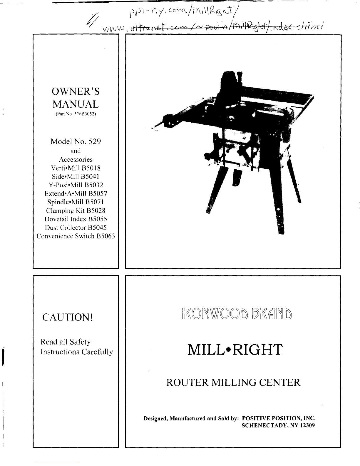
Mill-right 529 Owner's Manual
f
6r
r
-
0/
,
ro-r'.,.,/llr'f
\qAEl.I/
/
W^VU\U,
CAUTION!
Read all
Safety
I nstructions
Careful
ly
IKONWOOD DKAND
MILL.RIGHT
ROUTER
MILLING
CENTER
Designed, Manufactured and Sold
by:
POSITIVE POSITION,INC.
SCHENECTADY. NY I2309
OWNER'S
MANTJAL
(Part
No
:1t,B3052)
Model No. 529
and
Accessories
Verli.Mill
B5018
Side.Mill
85041
Y-Posi.Mill 85032
Extend.A.Mill
B5057
Spindle.N1ill
85071
Clamping
Kit 85028
Dovetail Index 85055
Dust
Collcctor
B5045
Convenience
Switch
85063

OWNER'S MANUAL
SAFETY
PRACTICES AND
INSTRUCTIONS
I.
GET TO
KNOW YOUR MILL.RIGHT
Read
and understand
your
owner's manual
and the
CAUTION! and
WARNING!
labels
in
the manualand
affixed to
the tool
. Learn the operations and
the
limitations
of the MILL.zuGHT
as
well
as
any
potential
hazards that
may
result from its
operation.
2. ROUTER SAFETY
Follow the
safety
practices
and
instructions
recommended by
your
router manufacturer.
Ifyour router requires
grounding,
be
sure
to
use
the
proper grounded
type receptacle.
3. KEEP WORK AREA CLEAN
Avoid accidents by keeping
your
work
area clutter free. Do
not
work
on waxed floors or floors covered
with
sawdust.
4. AVOID DANGEROUS CONDITIONS
Don't use
your
Mill.Right
in
damp or wet locations. Use
adequate
lighting.
5. KEEP
CHILDREN SAFE
Do not operate
with
children
present.
Remove
starter
keys
when not
in use.
Lock work
shop
when
not in use.
6.
DON'T FORCE THE TOOL
Do thejob better
and
safer
by
operating the router at the rate
and speed for which it was designed.
Don't
force
the
machine to
do
a
job
it
was not
designed for.
7.
CLOTHING
Do not wear
loose clothing,
gloves,
neckwear or
jewelry
which
can
get
caught in moving
machinery. Use non-slip
shoes.
Contain long
hair.
Roll
long sleeves above the elbow.
8.
USE SAFETY GLASSES
As a minimum, wear
safety
glasses
with
side
shields at all
times
(comply
with
ANSI Z'18.1). Use face or dust mask if
operation
warrants
and
ear
protection
during
extended
periods
ofoperation.
9.
LNATTENDED
MACHINE
Never leave
a running machine unattended. Be
sure
the
router
has completely
stopped before
leaving.
IO.
SECURE
WORK
Use clamps to secure
work to
work
surfaces.
When
..
-.
moved for operation, use
hold-downs or featherboa::r
against table and
guide
fence. When
possible.
free r:'-:
operate the machine.
1 I. DON'T OVERREACH
Maintain
footing and
balance
at all
times.
12.
CARE AND
MAINTENANCE
Use
only
sharp and clean tools. Follou router
r:- -':,.
-
maintenance
gu
idelines.
I3. DISCONNECT TOOLS
Turn
off
router
and unplug
it
when
chaneine b
:.
operations. Turn off
your in-line con\.::en.e
:
-
When
plugging
in
router,
be
sure rt
rs :.
::.. Oi
:
:.
14.
USE ACCESSORIES
DESI(
i\F.D
i
THE MILL.RIGHT.
See owner's manual for recommende:
:- --,i:.-- i
accessories may
result in hazardous
.
-','
15. DAMAGED PARTS
Damaged
parts
should be
properly
..i...
j
-<:
.:
--:-r'-
Check
for
alignment, movemen!.
t're:r:.:
'
:',-
r
-
may have been affected.
Repair or
:i:
3-.
before continuing operation.
16.
WORK
FEED DIRECTIT
tr.
Always feed
work
against the direc:..:
'
'
fixed.
feed the router into the
uork
::r
-i.'
,': .
--
I7.
STABILITY
The MILL.RIGHT
is
construcled.:
-:i,
-!
r
';-
any
tendency
for the unit to tip dur::.;
--
,:.:
-
be bolted to the floor or a suppon
:ia- :
'-
.'
. .
:-
securing them to the legs
and exten:
-
r
''
:-
potential
tipping.
I8.
CUTTING
LINE
Neither the
operator
or observer{
s
r: -
:
.L'
- .'
-
when
the
work is being moved
int.-
:-: ' -':.-
'
--:lt
'
:
;i
ct'ii
'-
l: li
:
-iiO0llC€
-':.3One.
.
.\
ITH
'-'
?r
-
::al
'.!--
l
-
rkis
-i
Jn.
'
::e is
.'-ruld
{l
by
l
l
O
1996,
Positive Position,
Inc
..iung
l9 ROUTING
S.{FETY USING THE
CONVENTIONAL
(BIT
UP)
ROUTING
STATION
Always feed
the work
against
the direction of
rotation.
Proceed counterclockwise
around the
outside of
a
workpiece.
Proceed
clocku ise around
the
interior of
a workpiece
(such
as a
cutout
or
a recess
in
the body
ofthe
workpiece)
Never
pass
the
rvorkpiece
between the router bit and
the
guide
fence. The
work
piece
could become
trapped
and
"kickback".
Note that
this
operation
would also
violate the
"counterclockwise
around the
outside
of
the
rvorkpiece"
rule.
When
plough
cutting through a
workpiece
(such
as
a dado
cut
with
the
router bit
pointing
up)
always be
aware that
the router bit will be hidden
until
it
emerges
from the
workpiece.
DO
NOT
PLACE
YOUR HAND
BEHIND
THE
WORKPIECE
AT
ANY
TIME. Use
a
push
stick or secure the
workpiece in a miter
gauge
equipped with a clamp.
Do
not release the
workpiece
until it has
passed
completell
bevond the
router bit.
Use a
featherboard to hold the workpiece against the
main
table
rrork
surface.
The
guide
fence is
equipped
* ith
a T-slot for mounting a featherboard.
A featherboard
designed
specifically
for
this
operation
is available fronr
IRONWOOD/MILL.RIGIIT. Refer to
the
accessories
catalog.
Use
a featherboard to hold the workpiece
against
the
guide
fence. The miter
gauge
slot
is
also a
T-slot
rvhich
can be used
to
mount a featherboard. A
featherboard designed specifically
for
this operation
is available
from
IRONWOOD/MILL.RIGHT.
Refer
to
the
accessories
catalog.
Do not use
warped,
twisted
or cupped stock.
Do not
attempt to flatten
a
warped
workpiece
by
the force of
hold downs or featherboards. These devices are
meant to hold only
flat
stock against the
work
surfaces.
Use
a bit
guard
whenever
your
operation
allows
its
use.
The
bit
guard
will help keep
your
hands away
lionr
the router
bit
during operation.
Ner
er
turn
the router "ON" before clearing the work
surfaces oftools, wood scraps etc.
not intended for
use
with
the
planned
operation.
OWNER'S MANUAL
SAFETY
PRACTICES
ANDINSTRUCTIONS
(CONTINUED)
.
Wlen using the VERTI.MILL
accessory, be sure
that
the
workpiece
is
securely
clamped.
Keep both hands
on
the
fixture
when routing.
.
Do
not
attempt to
move
or
adjust any
paft,
fixture,
hold down,
machine
part
etc. while the
router bit
is
still
turning.
r
Do
not
use
this
station
for
"plunge
type" operations
by
pressing
the work
down onto
the
rotating router
bit. Use the
router
caniage station with
a
"plunge
rype"
router
for this operation.
r
Close the split fence as close as
possible
to the
router
bit
to
prevent
cocking of the work as it
passes
the
opening in
the
fence.
20. ROUTING
SAFETY
USING
THE
ROUTER CARRTAGE
(BrT
DOWN)
ROUTING
STATION
o
Always feed the work
against the
direction
of
rotation.
.
Proceed
counterclockwise around the outside of a
workpiece.
o
Proceed
clockwise
around the interior
of
a workpiece
(such
as
a cutout or
a recess in
the body of the
workpiece).
o
Always
check that
the work
is securely clamped
before turning on the
router.
.
Backrouting is not recommended.
o
Make
sure
that
no machine
parts
are
in
the
line
of
travel ofthe
router
bit for
your proposed
operation. If
machine parts
are in
the
line of travel, use
travel
stops
or other suitable means of
preventing
the
router
bit
from contacting metal
parts.
o
Do not
attempt to remove
the
work or any machine
parts
while the router bit is still
rotating.
.
Keep both hands on the router handles
or
the router
caniage
when routing.
.
Take small
cuts rather
than
large. The
MILL.RIGHT
was designed with
precision
positioners
which
allow
you
to
proceed quickly
with smaller cuts for safer
operation
and
a better finish.
o
The router carriage
router
station was designed to
enhance safery by clamping the work
in place and
moving the
router
along a
controlled
predetermined
path in
its carriage.
Do
not
let
this
controlled situation
lull
you
into carelessness. A SECOND OF
INATTENTION CAN
RESULT IN SEVERE
INJURY.
O 1996. Positive
Position.
Inc.
512-tr-96

OWNER'S
MANUAL
CONTENTS
AVAILABLE ACCESSORIES
Safety
Practices and Instructions
I
Verti'Mill
Main
Assembly Instructions
5
Assembly Instructions
Step
l, Assembling the Leg
Set
5 Adjustment Instructions
Step 2,
Assembling the Base
5 Application Instructions
Step 3,
Assembling the Main Table to the Base
6 Assembly Figure
Step
4, Assembling the X-Positioner
6
Assembled Figure
Step 5,
assembling the X-Y Caniage
7 Application
Figure
Step
6,
Assembling the Guide
Fence 8
Basic Operation. Fig.
I
Step 7,
Assembling the Auxiliary Milling Table
Support 8 Basic Operation, Fig.
2
Step
8,
Assembling the
Auxiliary
Milling
Table
(AMT)
9
Basic Operation. Fig. 3
Step 9,
Assembling the Router Carriage
9 Basic Operation,
Fig.
4
Step
10, Assembling the Carriage Lock
l0
Y-Posi.Mill
40
40
40
40
4l
42
43
44
45
46
4',7
48
48
49
50
5l
)i
53
<t
51
55
56
5'7
58
59
60
60
6l
62
63
63
64
65
65
66
o/
68
Main Assembly Figures I through
9
Fig. I Assembling the
Base and Leg
Set
Fig.2 Assembling the Main Table
to
the Base
Fig. 3 Assembling the X-Positioner
Fig.
3A
Assembled X-Positioner
Fig. 4 Assembling the X-Y Caniage
Fig. 44.
Assembled
X-Y
Carriage
Fig. 5 Assembling the Guide Fence
Fig.
5A Assembled Guide Fence
Fig. 6 Assembling the AMT Support
Fig.
6A
Assembled AMT Support
Fig. 7 Assembling the AMT
Fig.7A Assembled AMT
Fig.
8 Assembling the Router Carriage
Fig. 8A Assembled Router Carriage
Fig. 9
Assembling the
Carriage Lock
Adjustments
Adjusting
the X-Y Carriage
Adjusting
the X-Positioner Acme Nut Pre-Load
Adjusting the Auxiliary Milling
Table
(AMT)
Adjusting the
Guide
Fence
Adjustment
Figures,
Main Assembly l0 through l4
Fig. I0 Adjusting the Router Carriage
Fig. 1l Adjusting the AMT
Support
Fig. 12 Adjusting the AMT
Fig. l3
Adjusting
the AMT
Fig. l4 Adjusting the
Guide
Fence
Basic
Operations
Using the X-Positioner Scales
Using the Router Table Station
Using the Router Carriage
Station
Planing with the
Router Carriage Station
Basic Operation
Figures
Figs. l
-4
Basic Operation
Figs. 5-8
Figs.9-10
Basic
Operation
Basic
Operation
Using the
X-Positioner Scales
I I Assembly Instructions
I
I Application & Adjustments
12 Assembly Figure
l3 Assembled Figure
14 Application Figure
l5
Application Figure
(Rear
r
ie*
)
l6
17 Side.Mill
l8 Assembly lnstructions
19 Application &
Adjustments
20 Assembly Figure
2l
Assembled Figure
22 Application Figure
23
Operation
Figure
24
25 Extend.A.Mill
Assembly Instructrons
Assembly
Figure
Assembled
Figure
Dust Collector
Assembly lnstruction.
Assembly
Figure
26
26
26
27
27
28
28 Dovetailing Index Plates
29
Assembly Instructrons
30 Assembly Figure
3l Assembled Figure
32
Optional Set-ups Frgurc
33 Spindle.Mill
33
Assembly
Instructions
34 Application & Adjustments
35
Basic
Operation
Instrucrrons
36 Assembly Figure
37 Assembled
Figure
37 Application
Figure
38
39
Convenience Srvitch
39
Clamping Kit
59
69
-0
-l
-l
J
-{
'76
@
1996, Positive Position,
Inc.
5
l2-
r r-96
OWNER'S
MANUAL
ASSEMBLING
THE MILL.RIGHT
MODEL 529
PLEASE READ THESE INSTRUCTIONS
THOROUGHLY BEFORE
ASSEMBLY
TO INSURE A
TROUBLE FREE EXPERIENCE. THESE INSTRUCTIONS
HAVE BEEN
TESTED ON NOVICES
AND WE
HAVE DONE OUR BEST TO WEED
OUT
PROBLEMS
FOUND
DURING
THIS
TESTING. IF YOU
SHOULD
EXPERIENCE ANY PROBLEMS, PLEASE
CALL
TOLL
FREE
888-478-2453 AND REQUEST A SERVTCE
CALL. A SET OF HEX
[ALLEN]
WRENCHES
AND A
COUNTERSINK
HAVE BEEN
PROVIDED FOR
YOU
CONVENIENCE. YOU WILL ALSO NEED
FLAT
TIPPED AND PHILLIPS SCREWDRIVERS
AND A SET
OF
BOX OR
SOCKET WRENCHES. THE ONLY
DRILLING YOU
WILL
HAVE TO DO IS FOR
YOUR
ROUTER
MOUNTING HOLES
IN THE ROUTER
SUPPORT
PLATES
AND
FOR
THE BRASS INSERTS INTO YOUR
WOOD FENCE INSERTS.
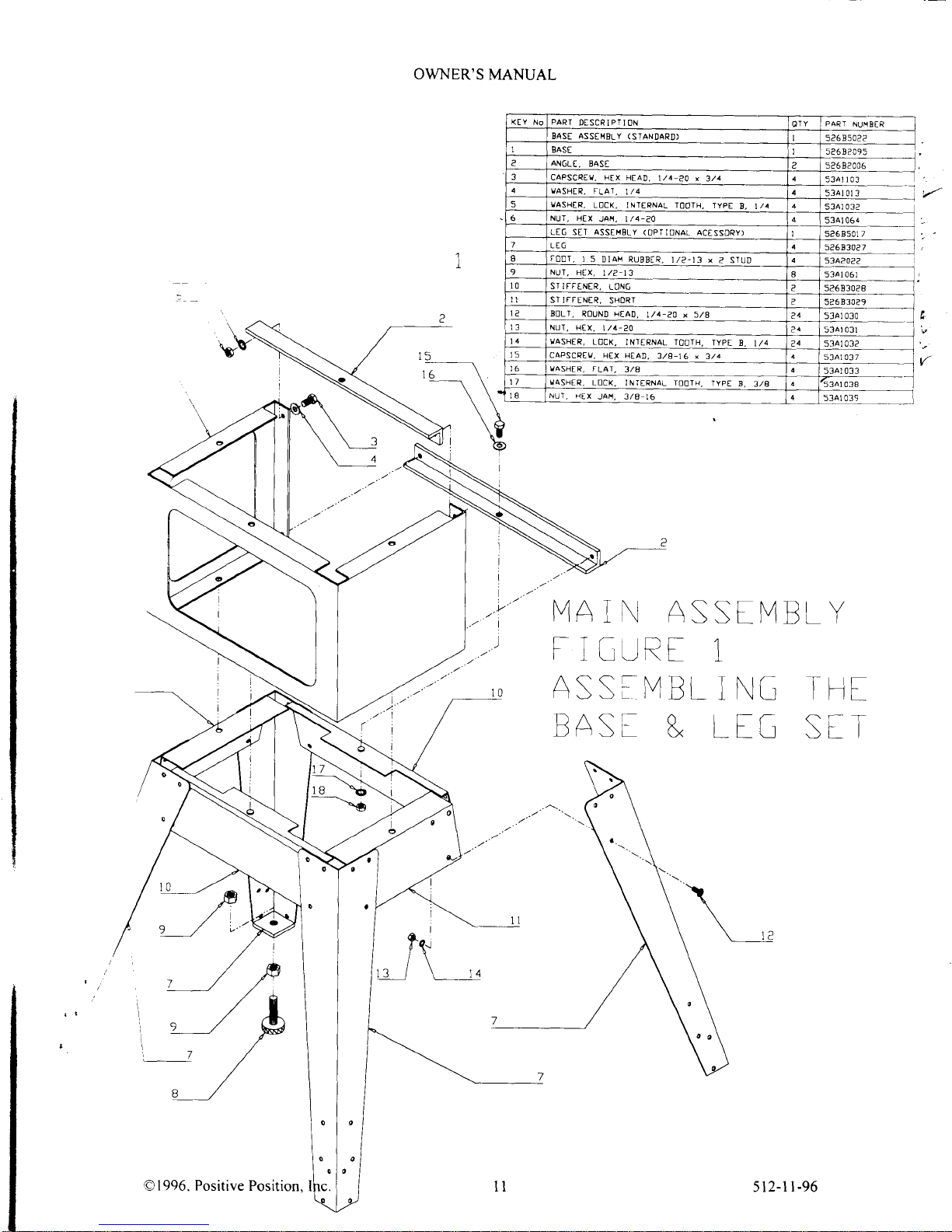
STEP
I
ASSEMBLING THE LEG
SET
(OptionalAccessory)
(Assembly
52685017)
Refer to
Figure
I
Find
the
parts
described by
Figure l key
numbers 7 through l4 in
the
quantities
indicated. Check
that
all hardware
items
match the
description
given
in the key
list.
Match
the three
bolt
holes
in
the
upper
end of each
Leg
[7]
to
the
matching
bolt
hole pattern in
the
ends of the Stiffeners
[0] & [l
l].
The
two Long
Stiffeners
[0]
should be opposite
each other and the two Short
Stiffeners I I I ] should
be
opposite each
other.
The
Legs should be
positioned
outside the Stiffeners. Use
one
each of
Bolt
[2],
Nut
|31
and
Lock Washer
[3]
fbr each
of
the 24 holes.
Note the hardware
sequence
shown
in
Figure
l.
Do not
tighten
Bolts
until
all
Bolts
have
been inserted. Then be
sure to securelv tighten all Bolts.
Thread
one Nut
[9]
onto
each Foot
[8].
About I inch of thread should extend past
the Nut.
Insert
one of these assemblies into the
bottom
hole
of each
Leg.
Thread the remaining Nuts
[9]
onto the
Feet
[8].
Note
the
harduare sequence
shown in Figure l.
Hand tighten the top Nut and place the
assembled
Leg
Set on its Feet. Once
you
hale completed the
MILL*RIGHT assembly and
positioned
it in
your
shop,
level
the feet and securely tighten
the top Nuts
[9].
STEP 2
ASSEMBLING THE
BASE
(Assembly
52685022)
Refer
to Main Assembly
Figure I .
Find
the
parts
described by
Figure l
key numbers I through 6 in the
quantities
indicated. Check that
all
hardware items
match the
description given in
the key list.
If
you
have
purchased
Lee Set
52685017,
position
the
unit
Base
[
]
on
the
Leg Set and
align the
three 7
I 6 bolt
holes
with the
matching bolt holes
on
top of
the
Stiffeners in the Leg
Set.
Q.lote:
the
Base
is
.r nrmetrical
top to bottom so it
can't be
positioned
wrong.)
Loosely fasten the
Base
to the Leg Set
with
one
each of
Bolt
[3].
Washer
[4],
Washer
[5]
and
Nut
[6]
in each of these holes. Note the hardware
sequence
shown in
Figure l.
BoltoneAngle[2]tothetoprearoftheBaseasshowninFigure
l
usingthefwo5/l6holesandBolt[3],Washer
[-l].
\\
asher
[5]
and
Nut
[6].
Bolt the other Angle to
the
bottom
rear
holes.
Note that
the
Angles
are
positioned
inside
of
the
Base flanges. Bolt
the
bottom
Angle to
the Leg
Set
using the center hole in the
bottom
Angle
and
one
each
of Bolt
[3].
Washer
[4],
Washer
[5]
And Nut
[6].
Note the hardware sequence shown in Figurel.
When all
harduare is
in
place,
be
sure to securely tighten all bolts.
@
1996, Positive Position,
lnc
512-tt-96
OWNER'S MANUAL
STEP 3
ASSEN,IBLING
THE MAIN TABLE TO THE
BASE
Refer
to Main Assembly Figure 2.
(Main
Table
Assembly 52685021)
Find
the parts
described by
Figure 2
ke1 numbers I through 7 in the
quantities indicated. Check that all hardware items match the description
given in
the ker
lrst
Position
the
Main
Table
[1]
on the assembled Base
(step
2).
CAUTION:
The
tgble
*eishs
aporoximatelv
90 lbs
and
this sten may require assistance.
Be
sure
to position the table * rth the
"U"
shaped
end
and under side T-slot overthe
large
cut out hole
in
the
long side of the
Base.
Loosely secure
the Table
to the Base
using
the
holes in the top flange of
the Base
and
Bolt
[3]
and
Washer
[J].
When all hardrrare rs in
place.
be sure Io
securelv
tighten all bolts.
Attach two Positioner Levelers
[2]
to the underside of the
Table
as
5ho\\n in Frcurc l. usrng
Screw
[7]
and Washer
[6].
Thread
the
Thumbscrews
[5]
into the threaded
holes
oiPosrtrtne:
l.erelers
[2].
lnsert the six Locking Setscrews
[0]
into
the Router Supptrn
I)rt,n-ln
p1311'
lal
P.:;e
the Router
Suppon
Drop-ln
Plate
in
the
rabbetcd
recess in
the
Main
'l'able
and
Ir'rel tt u:rir{
thc lour.,.n:.':
I L
ir:rS Selscre$s.
Ad.lust
the side-to-side
fit
by ad.justing
the tu'o l.ocking Sr'tSCft'rrs
ltrt:ited rr: :he rtle:
Place
your
router on the Router Supporf
Drop-ln Plat.' an,l
ptr:ii.trr.
.i
lrr
i:itrrr i!,:\ 3nienl
access to the
controls.
Note
this
router position. Rernove
)our
router 5
phcn..lrc
b,ase
rr.: --:rS lt
J)
J:ern9:Jle.
scribe vour
router
base bolt
hole pattern
onto
the Router
Support
Drop-ln Pi,:ic l)rrl,
hrlr-
;.:-3-ronc::i
:.
:..
-:
:!ruter
base screns
andcountersinkthetopoftheRouterl\,lountingPlatcusrnS:hccct.rnis:.r\::.r\:ie;
'--\';i()\'Useflatheaded
scrcws of
the
fight threud und length lo
fully
engape the tupped httles
.:.
'.i-r
rt]urir
'r
: - :'.:' hare
to
buy
longer
screws
than
the
ones that come
with
)-our
router.
Anach thc frrLlir ii ::.. R-
-:.:
\tou:.:.:i
?
j:3
S'l
l:P
l
ASSENIBLI\C
tllf: Pr
ts;'
r
\i {
(Positioner
.-\::enrb." : l: 3
j
Ret-er to Main Assembly Figure
j.
Firrd the
panr
Jes.:.:;: :, i :-:r
I xcr 1-"':.-':.
. ::.:ough
24 in the
quantities
indicated. Check
that
all hardrvare itenrs nratch thc ;e:;::::..
-
i
.i:
iir ri3 ri.
.:
Placethe
Positioner Support
u]on
a
rrork
surt'ace
rllhe:::
: :::
e s-:::ce ;t :::: ,.
::::ranple.)
Insert
thetwoBall
Bearings[0] intothetwocounterbored]E'holes::i..::.e::s.-:'.i.Po::,-3-:-::.:r[].TheBall
Bearing outer diameter is designed
as a slip
fit into these brrrc: a..J,
l:i
B:..
Bea:lngs
s:..- : :3 \e::
jquare
to
the
bores
uhile
inserting to
prevent
binding.
Screu,the Fixed
End
Acrne
Nut
[3]
into the 5 l6-l8lrr:i:r.l rl::
,:,:
Cr:-:lase
?--: i .-r3: {ssembly
[2]
as
shown
in Figure
3. IMPORTANT! Tishten br hand onlr
Position
Carriage
Positioner
Assembl;
[2]
u
rth
the
r.
.e::::.: :r::
.-:'
'i'
a.:g:.e:
both ends
of Positioner Support
[1.
Insert Guide Rod
[-]
lh:..ugr.::,e :.:.
":
,::e eni l:
'
bearingboreof[2] andthenthroughtheboreattheothcrcnir,i'i.' \..;-::3.:Jitii-l
:l
surfaces of
[]then
secure
[7]
in
[]with
two
setscre\\s
[81
as
sii\\;i
:n F::-:e -:
With
the opening of
Il]
facing
y'ou.
insen Acnrc' Lerd:cre*
'91
:ni.. i:.e :!,re oi:r'.e :lshl
nanl Ball
Bearing
[10].
The
l/4-20
threaded end of
[9]
must be on
the rrghr l'hen :r'.rerJ'q
l.rn
\ra\
::io
i-.
,,rhrch
has
alreadybeenscrewedinto[2].Makesure[9] doesnotprojectrntothc.r3''\St)i -:'lirtdols.
Ih.n:.ici[9]
offuntil
thejawareaof
[3]
isclear.Alignthematingja*sof FrceEnd.{:;lerut
l;
',rr:n:retd*Sraii:i:n.trullr
engage
thc
jaws.
Holding
[4]
in
this
position,
continue scrolins
[9]
rnto
[-r]
rnj
i-l]
I'eepr:i
IJ]
as;..,:e ll
[-l]as
possible.
Whenthethreadsof[9]har,eengagedboth[3]and[1].both[-r]
andlll
'.rrll
r;:3)runir
\er:.s,rpAcmeNut
Spring
[6]
and then Acme Nut
Collar
[5]
over the
por-tion of
[9]
trhrch
ha: arreiJ\
rr>:ei
li.:'rr.gh
[-rl
and
[4].
Thread
[5]
onto
[1]
slightll'
compressing
[61.
''\
.:: ::.3
;
.
'
bores at
::.::.::.:,-;gh
the
-:i.
'\.ll
::e
outside
O 1996.
Positive
Positiorr
5ll-rl-96
OWNER'S MANUAL
STEP
4
ASSEMBLING THE POSITIONER
(CONTINUED)
Continue tuming
[9]
until it
passes
through
the
ID
of
the
BallBearing
[0]
on
the
left
and
projects
beyond
-
.
:frrut
5.5 inches.
Apply' a few
drops of light
machine oil
to the two O-Rings
fl
31 and slide
them
over the
end of Sleeve
Il I ]
"
-
;n is nearest
the
fwo
O-ring
grooves.
Position
one
O-Ring
in each
groove.
Next, slide Round
Scale
[4]
over
the
'
t-)-
Rings [ 3
].
The
scale markings of [ 4] must be
at
the end
of the
assembly
and the knurled
part
of
fl
4l must
-',
:..u
ard the center. If not, turn
il
4] around now.
Slide this assembly over
the
left
end of
[9].
Slide
the
bore
of
Crank Handle Assembly
[15]
over the end of
[9]
until
[9]
bonoms out in the bore. Secure
'
to
[9]
with Setscrew
[15-A].
Tighten
securely. Push
the
Crank Handle
and Leadscrew
Assembly all the
way to
-
i
:rsht. Thet/u20
threaded
end should
be outside the Positioner
Support Assembly
Il].
Apply two % Flat Washers
^
the Wave Washer
Il7]
and the
t/*20
Locknut
[
8]. Tighten the Locknut to remove
axial
play
of
the
::iscrew. Do not over tighten as this will make
the
Leadscrew difficult
to
turn.
Insert Setscrew
fl2]
into
Sleeve
and tighten.
Apply a few drops of light rnachine oil to Guide Rod
[7]
just
outside
of
the two linear
bearinss at both ends
'
,-
.rrriage Positioner
Assembly
[2].
Slide
the
Carriage Positioner Assemblv
[2]
back and forth
repeatedly
to work
-:
orl into
the
linear bearings. Wipe the Guide Rod
[7]
clean.
Place
Cover
[9]
on Positioner Support
[]and
secure with four
screws
[20].
Attach
Round Scale Indicator
- ' to cover
with
screw
[20].
Attach
Adjustable Positioner Indicator to Carriage Positioner
[2]
with Thumbscrew
-:; and Washer
[2a]
in
the sequence shown.
STEP
5
ASSEMBLING'THE X-Y CARRIAGE
i.cter
to Main Assembly Figure
4.
Find
the
parts
described
by
Figure
4 key numbers I through l5
in the
:uantities indicated. Check that all
hardware
items match the description
given
in the key
list.
Place the
bottom edge of the Positioner Assembly
[5268500 I ]
on top of
the Levelers.
[See
..*e lers in Main Assembly
Figure 2.1
Secure
the Positioner Assembly to the
Main
Table
[2]
with two
Capscrews
1,11.
Finger
tighten only at this time. Attach
Carriage Track
[6]
to the
Main Table using two Capscrews
[4],
three
\\
ashers I l
]
and three Disk
Springs [ 2].
Note that
the Disk Springs are near the edge
of
the
Main
Table
and
the
\\'ashers
are inboard.
Place two each
Washers
and
Disk
Springs below the table and
one each above.
[This
stack up
na1 change later when
leveling the X-Y Caniage Assembly.]
Slide the Linear Bearing Assembly
[7]
onto
the Guide
Rod
[3]. [Note:
if
you
have
purchased
the Clamp
Kit
85028,
slide the
two
Shaft
Collars
[5]onto
the Guide Rod as
.rell
placing
on
at each
end of the Linear Bearing Assembly.] Slide
one end of the Guide
Rod
into the %" bore of
:re
Carriage Positioner
IKey
No.2,
Main Assembly Figure 3.] Slide the'io" bore of the
Ball
Bearing
Caniage
\ssembly
[5]
onto the other end
of
the
Guide Rod. Screw two Capscrews
[8]
each into
both ends. Snug
tighten
only
:: this
time
with
the Allen wrench provided.
Screw
the
Support Angle
[4]
onto the ends of the
Caniage
Positioner
:nd
Ball Bearing Caniage Assembly
using four Capscrews
[9].Use
the
two Washers
[10]
on the Ball Bearing
.arriase
Assembly
end only. At this time,
go
back
and securely tighten
the two Capscrews [ 3]. Check
to
see that
:.:e
ball bearings of the Ball
Bearing Caniage Assembly are sitting on top of the
Caniage
Track. If necessary adjust
:r.e
position
of the Ball Bearing
Caniage Assembly.
Once
this is done, securely tighten the eight
Capscrews
[8]
&
.l
Turn the Positioner
Crank Handle to check that the X-Y
Carriage
Assembly
moves freely.
We will
level
the
X-
':
Carriage Assembly later.
Apply a few
drops of light machine oil to Guide Rod
[3]
just
outside of the
two linear
bearinss at both ends
: ::e
Lrnear Bearing Assembly
[7].
Slide
the
Linear Bearing Assembly
[7]
back and forth repeatedly to work
the
:nto
the linear
bearinss. Wipe the
Guide
Rod
[3]
clean.
rqq6
Posirive Position, Inc
512-tt-96
OWNER'S
MANUAL
STEP 6
ASSEMBLING THE GUIDE
FENCE
[526B5o
l o]
Refer to
Main Assembly Figure 5.
Find
the
parts
described by
Figure 5 key numbers I through 9
in the
quantities
indicated. Check
that all hardware
items match the description
given
in the
key list.
Attach the Right
Fence
Support
Bracket
[3]
and the Left
Fence
Support
Bracket
[4]
to the
Fence
Assembly
[2]
with four
Capscrews
[7].
Note that
the Left Fence Support
Bracket
[4]
has a
recess on the bottom to
provide
clearance
for the optional
Dust Collector attachment
85045.
Attach
the
resulting assembly to the X-Y
Caniage
Assembly of
Main Assembly
Figure 4 using four Capscrews
[7].
Make
two
Wooden Fence Insert halves
t4] & t5]
from scrap hardwood.
Wood Fence Inserts
should be %" thick
and 90" beveled on one end. Measure
the
distance
from the underside of
the Aluminum Fence
T-Slot to the
Main Table surface. Make the
width
of
the Wood
Fence Inserts equal
to this distance less
l/8". Make the
right Wood Fence Insert
12.5" long and the left Wood
Fence
Insert I l" long. Position the
Wood Fence Insert
halves with the bevel
in the center as shown and line up
the
beveled edge
with the center of the
Router Drop-ln Support
Plate
[Main
Assembly Figure 2 Key
No.9].
Holding the
Wood Fence
Insert against the Aluminum
Fence
[2]
and up
aqainst the Aluminum
Fence T-Slot, trace the outline of
the four
(4)
Keyholes in the
Aluminum Fence onto
the backs of the
Wood Fence lnserts. Mark
the
center of the
narrow
end of
each
Keyhole as shown. Drill a
flat bottom A318"
x 5i8" deep hole
in
the center of
each of the four
locations
marked. Thread the
four Brass Threaded
Inserts into these
holes. Insert the four Pan Head Phillips Screws
[9]
into the Brass Threaded
Inserts.
Slide
the heads of
the Pan Head
Philips
Screws
into the ke1'hole slots and
tighten
the Wood Fence
Inserts against the
Aluminum Fence in the
desired
position.
STEP
7
ASSEMBLING THE
AUXILIARY MILLING
TABLE
(AMT)
SUPPORT
Ref'er to
Main Assembly Figure 6.
Find the
parts
described
by Figure 6 key numbers
I through l8 in the
quantities
indicated. Check that all hardware
items match the description
given
in the key
list.
Bolt
the AMT Mounting Wedge
[2]
to the
AMT Support
[ ]
using two Capscreu
s
[7]
and
Locking Washers
[8].
Attach the Stop Pin Assembly
[12]
to
the AMT Support using two
Capscreu s
[13].
Pass
Capscrew
I
l]through Spacer
[0]
and
through Clamping Lever
[9]making
sure the hex
pan
of
the
Clamping
Lever hole is facing the
head of
Capscrew
[11].
Thread Capscrew
[11]
into the AMT Support clamping
flange as
shown.
Attach the Jacking Screw
Mounting Plate
[4]to
the
AMT
Support
underside using nvo
Pan Head Phillips
Screws [ 6].
Insert
Stud
[
8] into the Plastic T-Handle
Knob [ 7] and tighten using double
3
'8-
16 nuts Thread the
assembled
T-Handle/Stud into the Jacking Screw
Mounting Plate.
Drop
the
Jacking Disk [ 5] into the
top
of
the 2"
bore of the AMT Support.
Pass Capscrew
[6]through
Spacer
[5]and
through Clamping
Lever
[4]
Pass Capscreu'
[6]through
the l"
bore
of the AMT Support top
flange. through the
AMT Mounting Wedge and
loosely
screu
Capscrew
[6]
into the
AMT Mount T-Nut
[3].
Lift the entire assembly
and maneuver the
AMT llount T-Nut
[3]
into
either
end
of
the AMT Mounting T-Slot located
under the Main Table.
[See
Main Assembll Figure 2 for
location
of the AMT Mounting
T-Slotl. Slide the AMT Support
Assembly to a
position
at about
the middle of the
AMT Mounting T-Slot and lock securely into
place
using
the Clamping Lever
[5].
O 1996,
Positive Position. Inc
512-n-96
OWNER'S MANUAL
STEP 8
ASSEMBLING
THE
AUXILIARY MILLING TABLE
(AMT)
Ret-er
to
Main Assembly
Figure
7. Find
the parts
described by Figure 7 key numbers I
through l3 in the
quantities
indicated.
Check
that all hardware items match the description
given
in the
key
list.
Position the AMT
[ ]
on
a work
surface
with
the back showing as
in
Main
Assembly Figure 7.
Position
the
AMT SwivelHead
[2]
between the two 2"
bored
flanees
of
the
AMT
[]and
line up the bores of
both
parts.
The elons,ated slots
in the
2" shaft of
the AMT
Swivel
Head
[2]
should face away
from
the AMT
Il].
With
its
rhree
stop
pin
holes
to the left, slide
the
AMT Support
Pipe
[0]through
allthree 2"
bores until
it is flush
with the
rieht
face of the
right AMT
flanee. Slide the
AMT Swivel Head all the way
to the right until it contacts
the
left
rnside face of the
right AMT flanse. Loosely thread fwo
Setscrews
[3]
into the fwo
tapped holes in the top
of
the
\\1T
Swivel Head.
Inspect the
Stop
Pin Assembly
[7]
to
familiarize
yourself
with its operation.
Note the
position
irhich
detents the Stop
Pin
and
keeps it from
protruding
out
its hole. This is
thefree or detent
position.
Turning the
inurled
knob releases the Stop
Pin
and allows it to
project
from its hole. This is the
slop
position.
Attach the
Stop
Prn Assembly
[7]to
the underside of
the
left
AMT flanse using
fwo Capscrews
[8]
and
Flat
Washers
[9]
in the
.cquence
shown in Main Assemblv Figure 7. Turn the
Stop
Pin
knurled
knob
to
release it
to its.r/op
position.
Facing
lhe left end of
the AMT
Support
Pipe
[
0],
rotate
the
AMT Support Pipe so that the
Stop
Pin engages the
stop
pin
hole which is counter
clockwisefrom the middle
hole.
tNilh
the 2" shaft of the AMT
Swivel
Head
pointing
down,
)ecurely tighten the
two
Setscrews
[31.
Pass Capscrew
[6]
through Spacer
[5]
and Clamp Lever
[4].
Screw Clapscrew
l6l
into the clampine flange of the AMT. Lifi
the
entire AMT
Assembly and place
the
2"
shaft of the
AMT
Swivel
ttead into the top of the
2"
bore of the
AMT Support in
Main Assembly
Figure
6. Slide the AMT SwivelHead2"
r,haft
all
the wa1' to the bottom of the AM-f Support bore.
s fllP
9
ASSEMBLING T'HE ROUTER CARRIAGE
Refer
to
Main Assembly Figure 8. Find
the
parts
described by
Figure
8 key numbers I through 9 in the
.'1uantities
indicated.
Check
that all hardware items
rnatch
the description
given in
the key list.
Inspect
the
two
Side Brackets
[2].
Notice that
only one side of
each
is
machined
and the two Side
Brackets have opposite sides
rnachined.
Place the two
Side
Brackets
[2]
inside
the Router Mounting Plate
[ ]
with
rhe
machined
sides
facing the insides of the fbur
vertical tabs of the
Router Mounting Plate
[].
Attach the
Side
Brackets to the Router Mounting Plate using the four Plastic Knobs
[4]
and
Lock Washers
[5J
as
shown.
Position
Ball Bearing
Carriage
Assembly
[3]
under
the ends of the
Side
Brackets
as
shown.
Attach the Ball
Bearing Carriage
\ssembly
to
the Sidc Bracket
feet
using the
two
Round Head Square Neck Bolts
[7]
and Flat
Washers
[9].
Screw
the two Brass
Thumb
Scrervs
[6]
into
the U-channel ends of the Side Brackets as shown.
Refer to
Main Assembly
lrrgure
10.
Place the
completed
Router
Caniage Assembly
on the X-Y
Carriage
by
placing
the U-channel ends over
rhe Linear Bearing Assembly and tighten the Brass Thumb Screws
[6]
and
resting the
ballbearinss of
the
Ball
Bearing Carriage Assembly
[3]
on the Support Angle. Place
your
router on the
Router
Mounting Plate and position
rt to allow convenient access to the
controls.
[f
you
draw
an
imaginary line through the
router's
handles, that
line
should run
parallel
to the
Side
Brackets. Note this
router
position.
Remove
your
router's phenolic
base and
using
it
.ls a template,
scribe
),our
router
base
bolt
hole
pattern
onto
the
Router
Mounting Plate
[].
Drill holes
conesponding
to
your
router base
screws and countersink
the
bottom of
the Router
Mounting
Plate
using
the
countersink
provided.
CAUTIONI
Use
flat
heuded screws of the
right
thread and length to
fullv
enssse the
tapped
holes tn
your
router. You may have
to buy longer scrcws than the
ones
that
come with
your
router. Attach the
router
to the
Router Mounting Plate.
The
Router Carriage
is vertically
adjustable. Loosen the
Plastic Knobs
[4]
just
enough to move the Router
Carriage
up
or down
-
then
retighten.
The
Router Carriage
should be level with
respect
to the Main Table. A simple
\\ a\
to do this is to lower
the Router
Carriage onto a flat
board covering
the
"U"
shaped opening at the
right end of
the Main
Table.
With
the
Router
Caniage sitting on
the flat board, tighten the Plastic Krobs
[4].
Use
thicker or
more boards to
raise
the Router Carriase level or a thinner board to lower it.
e'
1996, Positive Position, Inc
512-11-96
OWNER'S MANUAL
STEP IO
ASSEMBLING
THE CARRIAGE LOCK
Refer
to
Main Assembly Figure 9.
Find the
parts
described by Figure 9 key numbers I
through 6 in the
quantities indicated.
Check that all hardware items match the description
given
in the ke1 list.
Pass the Stud and Handle Lock Assembly
[2]
through the Bronze Flat
S'asher
[.1]
and nro Disk
Springs
[5].
IMPORTANT! The Disk Springs are dished
which
is
what gives
them their
spring Be sure the Disk
Springs are ananged such that they are touching back to back at their center holes. Next.
pass
the
stud through the
3/8" bore at the
rear
of the Ball Bearing Caniage Assembly
[ ].
Place the Lock Clamp Angle
[3 ]
over the srud
and
thread
the Locknut
on
the
end of the stud. The Lock Clamp Angle must engage the top flange oi the
Carriage Track
[Main
Assembly Figure 4,
Key No. 6]. The Carriage Lock Assembly is unlocked
when
the *nob is vertical
and
locked when the knob
is horizontol. Adjust the Locknut
[6]
to
give
adequate Drsk Sprine force to lock
the carriage.
IMPORTANT!
Do
not
over tighten the Locknut as
excessive
locking force
rr
rll cause the
b,all L'e arings to tarl
prematurely.
With the Caniage Lock Assembly in the
unlocked
position.
the \-\
Carriase
.:.r:ld
mor.e tieelr
when the Positioner
Crank Handle is turned. CAUTION! Do not turn
lhe Pc)srliofrcr
Cra:r' ii.:.:.iie
uith
the Caniase
Lock Assembly in the lock
position
as this may damage the
Positroner.{ssemb,r
l0
e
1996. Positive
Position. Inc.
OWNER'S
MANUAL
t/
MA i \,1
ASSTIVBLY
t
I Gt,] RT
I
ASSIiVEL
I
i\G
-tFrl
EASI
&
L[G
SI-t
PART
DESCRIPTI
BASE
ASSEMBLY
(STANDARD)
CAPSCREU. Htx HEAD.
1/4-20 \
3/1
VASHER,
FLAT
I /{
INTERNAL TOOTH,
TYPE
B, I/4
NUT,
HEX
JAH, I/4-20
T ASSEHBLY
(OPTIONAL
ACfSSORY)
'ODI,
I 5
DIAH RUBBIR,
l/?-13
x ? STUD
NUT,
HEX,
I,/2_I 3
SIIFFENER,
LON6
STIFFTNER,
SHDRI
BoLT. RoUND AEAD,
I/4-2o x 5/8
NUT, HfX,
I,/4.20
VASHER,
LOCK,
INTfRNAL TOOTH,
TYPt
B,
I/4
CAPSCREv,
HEX HEAD.
3/8-16 x
3/a
IASHER,
FLAI,3/A
R,
LUCK, INTERNAL TOOTH,
T"ti.iA
NUT, HfX
JAX, 3/8
l6
53al 033
c-
4{!
l't / \ t4
O
I 996. Positive
Position.
512-l
l-96

OWNER'S
MANUAL
L-l,-l
(/)
{
an
T
l--
;*,
J
rrtu
{
(/)
I
7)
<-
r
z
:
',/
.a-,{
*
a,-
Z
t2
ll
ll
l"i
tl
-l
\1
2
:l
;
tl
-1
v,l
a)
I
I
i
l
r-i
lel
zi
iIl
]F
l:i
+
hl
si
ll
u
\
512-l
l-96
@1996,
Positive
Position,
Inc.
 Loading...