

Page 1

Installation and User
Guide
Pellicon® 3 Cassettes
Contents
Introduction ..................................... 2
Membrane Type ........................... 2
Pump Capacity ............................ 2
Water Quality .............................. 2
Installation ...................................... 2
Pellicon® 3 88 cm2 and 0.11 m2
Cassette Holder Installation ........... 2
Pellicon® 3 0.57 or 1.14 m2 Cassette
Benchtop Holder Installation .......... 3
Manual Process-Scale Holder
Installation ................................. 4
Hydraulic Process Scale Holder
Installation ................................. 5
Maintenance ................................... 7
Flushing and Cleaning ....................... 7
Flushing ..................................... 8
Cleaning ..................................... 8
Sanitization ..................................... 9
Depyrogenation .............................. 10
Integrity Testing ............................. 10
Measurement of Normalized Water
Permeability................................... 11
Storage ......................................... 12
Troubleshooting .............................. 14
Warranty ....................................... 15
The life science business of Merck KGaA, Darmstadt,
Germany operates as MilliporeSigma in the U.S. and Canada.
Page 2
Pellicon® 3 Cassettes Installation and User Guide 2
Introduction
This guide provides installation and
maintenance procedures for Pellicon® 3
cassettes. It is not intended to provide
validation protocols or supporting data
for validation purposes. Please refer
to the cassette Validation Guide for
this information. Please refer to the
Certificate of Quality supplied with each
cassette for specifications.
Membrane Type
Install filters containing only one type
of membrane in the filter holder at one
time. Do not mix filters with different
pore sizes or nominal molecular weight
cutoffs. The area of membrane used
depends on the filter surface area
required for your particular application.
Pump Capacity
When operating Pellicon® 3 cassettes,
select a pump with adequate capacity.
Recommended feed crossflow rate for
cassettes is 4 - 6 liter/min/m2. Optimal
cross flow will depend on the actual
solution being filtered.
Water Quality
Reverse osmosis (RO) water or water for
injection (WFI) is recommended
Installation
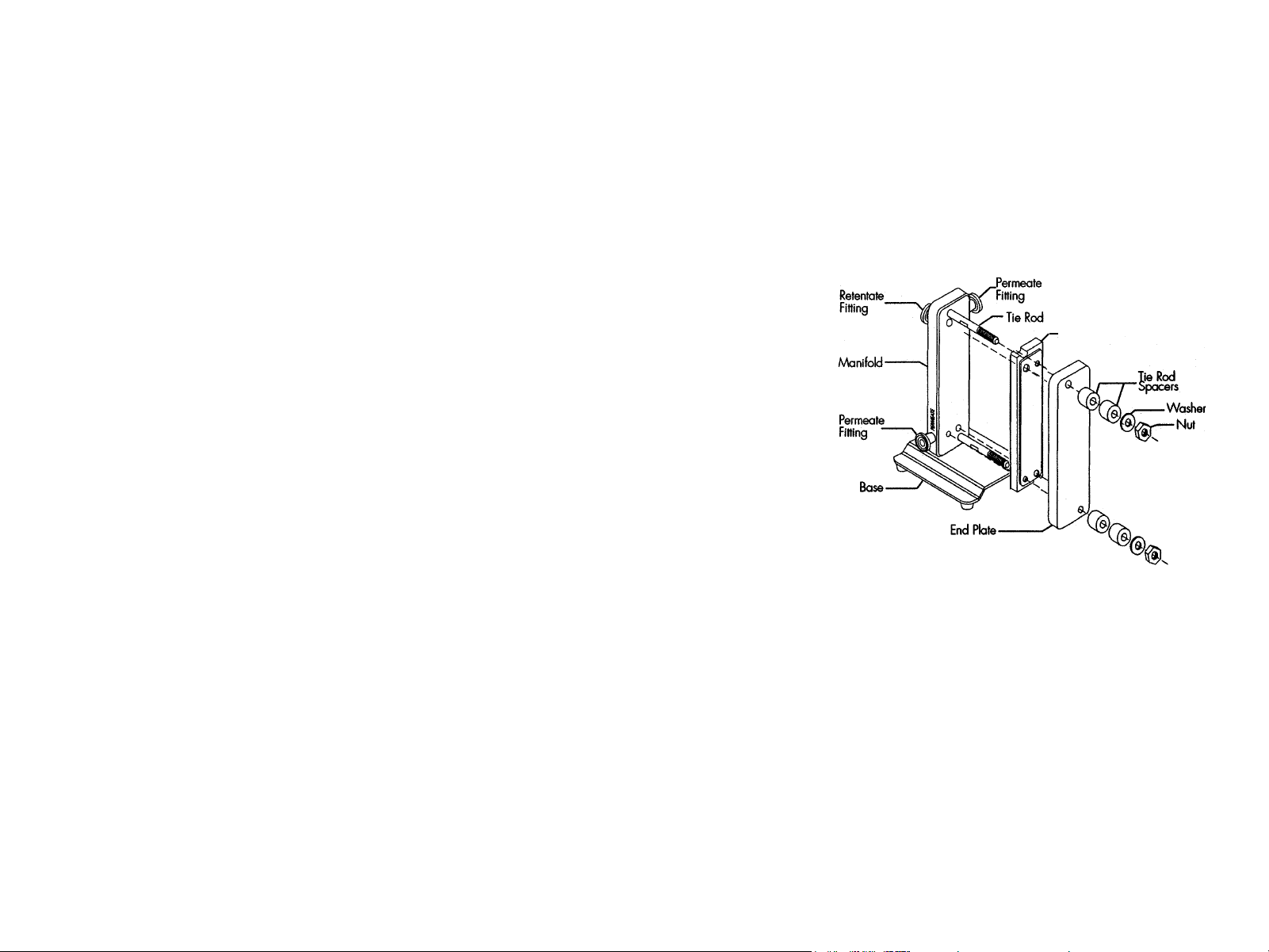
Pellicon® 3 88 cm2 and 0.11 m2 Cassette Holder Installation
NOTE
Pellicon® 3 88 cm2 and 0.11 m2 Cassettes must be installed in a Pellicon®
Cassette Holder, Catalog Number XX42PMINI.
Holder Installation
1. Loosen the nuts on the tie rods of the
holder and remove the nuts, washers,
tie rod spacers and end plate.
2. Inspect the tie rods and nuts for signs
of burrs or stripped threads. Replace
any damaged components. Nuts must
turn freely on the tie rods to ensure
proper tightening of the holder.
3. Slide the Pellicon® 3 Cassette onto
holder so that the tie rods pass
through the cutouts in the Pellicon®
3 Cassette. Repeat to install one or
two additional Pellicon® 3 Cassettes
if required.
4. Slide the end plate onto the tie rods
and press the end plate against the
cassette.
5. Install the tie rod spacers, washers and nuts. Hand-tighten the nuts, alternating from one
nut to the other nut.
NOTE
Uneven tightening of the nuts can damage the Pellicon® Cassette. Nonparallel
plates or compression of the filters at one end can cause leakage.
Pellicon® Cassette Holder, XX42PMINI
Pellicon® 3 Cassette
6. Tighten the nuts using the torque wrench and 9/16 in. socket supplied with the
Pellicon® Cassette Holder. If your wrench has a ratchet head, move the lever to the
right lock position to tighten the nuts or to the left lock position to loosen the nuts.
Page 3

Pellicon® 3 Cassettes Installation and User Guide 3
7. Set the torque wrench at 180 to 200
in. lb. (20.3 to 22.6 Nm) by holding
the spring loaded lock collar down
and turning the handle until the 180
to 200 in. lb. (20.3 to 22.6 Nm)
mark aligns with the 0 (zero) mark
on the collar.
8. Rotate the handle slightly to spring
the lock collar back into place.
9. Attach the socket to the torque
wrench by firmly pressing the socket
onto the torque wrench drive.
10. Place the socket over one nut. With a
continuous motion, turn each nut ¼
turn, alternating between the nuts,
until the wrench clicks, which will
indicate it has reached the set force.
Pellicon® 3 0.57 or 1.14 m2 Cassette Benchtop Holder Installation
XX42P0060 Pellicon® Cassette Acrylic Filter Holder
XX42PRV60 Pellicon® Cassette Acrylic Holder Low Retentate Volume
XX42P0080 Pellicon® Cassette Stainless Steel Holder
XX42P0K80 Pellicon® Cassette Stainless Steel Holder Assembly
1. Loosen the nuts on the tie rods of the holder and remove the nuts, washers and end plate.
2. Inspect the tie rods and nuts for signs of burrs or stripped threads. Replace any
damaged components. Nuts must turn freely on the tie rods to ensure proper
tightening of the holder.
3. Clean the manifold adapter plate (XXPEL3MAP) with an alcohol wipe.
4. Slide the manifold adapter plate onto the holder against the holder’s manifold
plate, with the solid light grey side labeled “Manifold Side” towards the manifold,
and the wings resting on the tie rods. Slide the manifold adapter plate directly
up against the stainless steel manifold.
5. Slide the Pellicon® 3 cassette up against the manifold adapter plate. The dark
grey center with light grey perimeter of the manifold adapter plate should be up
against the Pellicon® 3 cassette.
6. Slide a Pellicon® 3 Cassette onto the holder.
7. Slide the end plate with the handle side up onto the tie rods.
8. Tie rod spacers (XX4200066) are available when operating the system with low
membrane area. Place enough spacers on each rod so that the length of exposed
threaded tie rod is less than the length of the hex socket. Replace the washers
and nuts. Hand tighten the nuts in a diagonal pattern.
NOTE
Uneven tightening of the nuts can damage the Pellicon® Cassette. Nonparallel
plates or compression of the filters at one end can cause leakage.
9. Tighten the nuts using the torque wrench and 15/16 in. deep hex socket supplied
with the Pellicon® Cassette Holder.
10. Set the torque wrench by turning the knurled locking collar clockwise or by pulling
the handle out to unlock. Turn the torque setting scale clockwise until the 350 in-lb
(40 Nm) mark on the torque scale is opposite the zero mark on the smooth collar.
Turn the knurled locking collar counterclockwise to lock.
Page 4
Pellicon® 3 Cassettes Installation and User Guide 4
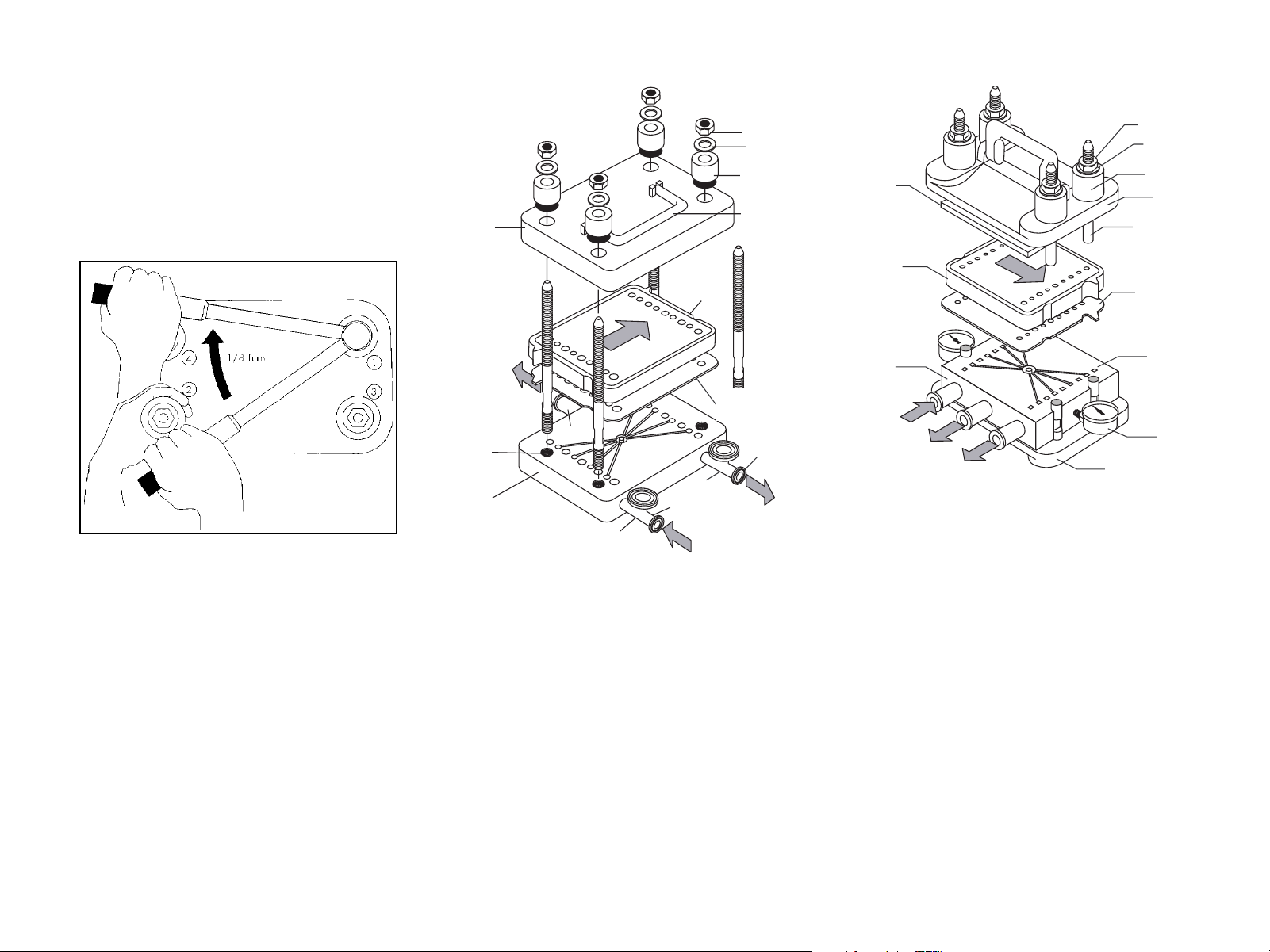
of tie rods
pressure plate
11. Using the torque wrench and 15/16 in.
deep hex socket, turn each nut 1/8 turn
in the sequence shown here. When the
wrench clicks, this indicates that the set
force has been reached. DO NOT OVER
TORQUE. Evenness of torque is critical
to system performance.
top
plate
manifold
threaded
tie rod
Pellicon
Cassette
®
hex nut
washer
stainless steel
bushing
handle
top acrylic
Pellicon
Filter
MILLIPORE
®
nut
washer
stainless steel
bushing
top
pressure plate
tie rod
manifold adapter
Gasket Plate
plate
Pellicon® Holder Tightening Sequence
NOTE
Depending on the results of the
Integrity Test, the torque may need
to be increased at intervals of 50
in-lb (5.6 Nm) up to a maximum of
550 in-lb (62 Nm).
12. Recheck the torque prior to use.
NOTE
If the filter holder is tightened in a
cold area and moved to a warmer
area, loosen the nuts entirely, let
the filter holder warm up, and then
retighten to prevent warping of the
end plates.
PERMEATE
threaded
holes for
insertion
bottom
plate
manifold
permeate
outlet port
1in. sanitary
Tri-Clover®
connection
retentate
outlet port
feed inlet
port
FEED
manifold adapter
Gasket Plate
plate
3/4 in. sanitary
Tri-Clover
®
connection
RETENTATE
bottom
manifold plate
FEED
PERMEATE
RETENTATE
pressure plate
Exploded View of Acrylic Pellicon®
Cassette Filter Holder.
bottom
permeate
manifolds
(four holes)
pressure
gauge
Exploded View of Stainless Steel Pellicon®
Cassette Filter Holder.
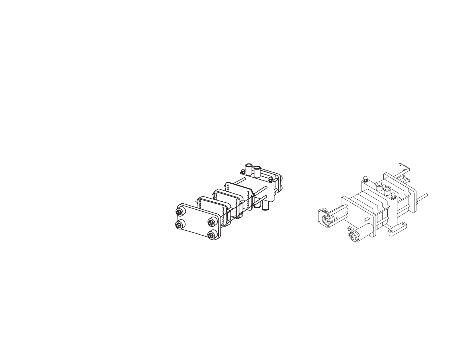
Manual Process-Scale Holder Installation
1. Loosen the nuts on the tie rods of the holder and remove the nuts, washers and
end plate.
2. Inspect the tie rods and nuts for signs of burrs or stripped threads. Replace any
damaged components. Nuts must turn freely on the tie rods to ensure proper
tightening of the holder.
3. Clean the manifold adapter plate (XXPEL3MAP) with an alcohol wipe.
4. Slide the manifold adapter plate onto the holder against the holder’s manifold plate,
with the solid light grey side labeled “Manifold Side” towards the manifold, and the
wings resting on the tie rods. Slide the manifold adapter plate directly up against the
stainless steel manifold.
Page 5
Pellicon® 3 Cassettes Installation and User Guide 5
5. Slide the Pellicon® 3 cassette up against the manifold adapter plate. The dark
grey center with light grey perimeter of the manifold adapter plate should be up
against the Pellicon® 3 cassette.
6. Replace the spacers, washers and nuts as shown in Figure 5. Hand-tighten the
nuts in a diagonal fashion (see Figure 4). Use a few drops of suitable lubricant on
the tie-rods and between the nuts and the washers if required.
Note Uneven tightening of the nuts can damage the Pellicon® 3 Cassette.
Nonparallel plates or compression of the filters at one end can cause leakage.
7. Tighten the nuts using the torque wrench and 15/16 in. deep hex socket supplied
with the Pellicon® 3 Cassette Holder.
8. Set the torque wrench by turning the knurled locking collar clockwise or by pulling
the handle out to unlock. Turn the torque setting scale clockwise until the 350 in-lb
(40 Nm) mark on the torque scale is opposite the zero mark on the smooth collar.
Turn the knurled locking collar counterclockwise to lock.
9. Using the torque wrench and 15/16
in. deep hex socket, turn each nut
1/8 turn in the sequence shown in
Figure 4. When the wrench clicks,
this indicates that the set force
has been reached. DO NOT OVER
TORQUE. Evenness of torque is
critical to system performance.
Hydraulic Process Scale Holder Installation
The Hydraulic Closure with Manual
Controls is intended for use with the
Millipore Process Scale Filter Holder. It
will maintain appropriate pressure on
the holder during processing or during
storage of installed filter cassettes.
RUN mode is required for process
operations. The system hydraulic pressure
is maintained at 1800 psig ± 100 psig.
In STORE mode, the system may be
stored with the Pellicon® 3 cassettes
installed. The system hydraulic pressure
is maintained at 1200 psig ± 100 psig.
Note Depending on the results of the
Integrity Test, the torque may need
to be increased at intervals of 50
in-lb (5.6 Nm) up to a maximum of
550 in-lb (62 Nm).
10. Recheck the torque prior to use.
Process Scale Holder
Hydraulic Process Scale Holder
1. Set the System Mode switch to DUMP.
Note
Check the Hydraulic Pressure Gauge
on the hydraulic power unit panel to be
sure the pressure is relieved. Do not
proceed until the hydraulic pressure
reaches 0 psig as read on gauge PI-2.
Page 6

Pellicon® 3 Cassettes Installation and User Guide 6
2. On the first holder level (if there
are more than one), remove the
TC clamps and inserts holding the
hydraulic cylinders to the clamp rods.
3. Loosen and remove the hand wheels
on the clamp rods at the opposite
end plate (of the same holder level).
4. Slide the end plate away from the
manifold segment, creating an
opening for cassette insertion into
the holder.
5. Slide the manifold adapter plate
or a stainless steel support plate
onto the holder against the holder’s
manifold plate.
6. Slide a Pellicon® 3 Cassette onto the
holder. Up to ten 1.14 m2 cassettes
may be installed per side if required.
7. Slide the end plate back against the
cassette assembly.
8. Install the grooved clamp rods, TC
clamps and inserts and the hand
wheels.
NOTE The hand wheels require hand
tightening only. Ensure that each
end plate is flush against the
cassette assembly and both hand
wheels are snug against the end
plate. Not less than one inch of
excess thread on the clamp rod
exiting the hand wheel should be
exposed.
Holder Pressurization and
Operation
1. The hydraulic fluid reservoir must be
full (indicated on the level indicator
inside the Hydraulic Power Unit).
2. All hydraulic flex hose connections
must be installed from the
Hydraulic Power Unit to the
hydraulic cylinders.
3. All hardware on the clamp rods
must be in place. Tighten the hand
wheels until they are hand-tight.
4. Turn on the air supply to the
Hydraulic Power Unit. A minimum
of 80 psig air pressure should be
available. Check the air pressure
on the pressure gauge PI-1 on
Hydraulic Power Unit front panel.
5. The Power Switch on the Hydraulic
Control Unit HS-1 must be in the
ON position, and the green Power
Indicator must be illuminated.
6. Set the Operating Mode Selector
Switch, HS-3 to RUN or STORE, as
required.
7. Set the System Mode Selector
Switch, HS-2 to ENABLE. The
hydraulic closure system will close
the holder assembly and maintain
the appropriate pressure on the
holder for either RUN or STORE
mode, as selected.
the System Pressure Manual Dump
Valve, MV-1 on the left side of the
Hydraulic Power Unit.
Caution
The hydraulic closure system must
remain connected to the holder
during processing and during
storage of installed cassettes. The
hydraulic closure system must be
depressurized before connecting
or disconnecting fittings. If the
position of the Operating Mode
Selector Switch (RUN or STORE)
is changed while the system is in
ENABLE mode, the hydraulic system
pressure will drop to 1000 psig
and then increase to the correct
pressure for the new selected mode.
If the hydraulic system pressure
drops below 1200 psig while in
RUN mode or 800 psig while in
STORE mode, the relevant Low
Pressure Alarms (PAL-1 or PAL-2
respectively) will be illuminated and
the Alarm Horn will sound. Once
the problem has been corrected and
hydraulic pressure restored, the
alarm condition may be cleared by
pressing the Alarm Reset – Resume
Operation Push-button.
9. Repeat the procedure for any other
holder levels.
8. To relieve hydraulic system pressure
at any time, set the System Mode
Selector Switch to DUMP or open
Page 7

Pellicon® 3 Cassettes Installation and User Guide 7
Maintenance
Pellicon® 3 Cassettes must be operated while under compression from the holder
assembly to ensure that the cassettes will seal properly. The compression is supplied
by applying torque to the nuts on the threaded tie-rods of the holder assembly. If
proper holder maintenance is not performed, higher torque values will be required to
achieve proper sealing.
The following steps are recommended to keep the holders in operational condition:
1. Clean nuts, washers and tie-rods before every use to ensure that they are free of
particles. A mild solvent such as IPA and water is generally effective.
2. Use a few drops of suitable lubricant on the tie-rods and between the nuts and
the washers, whenever permitted. This could be a food grade vegetable oil or
glycerin.
3. Check with your Quality Assurance department before introducing a new
lubricant into your production facility.
4. Protect the tie-rods from receiving any blows that could damage their threads,
which can lead to galling. Particular care should be taken when using a torque
wrench near the tie-rods.
5. Replace any component that is visibly worn or does not spin freely.
Flushing and Cleaning
Flushing and cleaning are required for
following process steps:
Storage Solution Removal
Pre-use flushing and cleaning steps are
performed to remove shipping solution.
A minimum of 60 liters of solution per
m2 of membrane should be used in a
combination of flushes and recirculation
cleanings.
Preprocess Equilibration
A flushing step is utilized to ensure that
the system and cassettes are properly
prepared for processing. The flushing
solution may be something other than
water depending upon the initial solution
used for the process.
6. Rates of wear will vary from system to system, but replacement of nuts and
washers should be considered after every ten installations, to maintain high
sealing force in the holder.
7. When new nuts do not spin freely, refurbish the threaded rods with a 5/8 in–18
die.
8. It is recommended that a set of spare parts be kept on hand at all times.
Post Process Cleaning
Cleaning and flushing steps are
performed after product recovery
and is intended to clean and sanitize
the system and restore clean water
permeability and process flux to within
range. Some applications may require
a two-step cleaning procedure. In these
cases it is imperative that the primary
cleaning agent be flushed completely
from the system to avoid potentially
harmful chemical reactions between
cleaning agents. A full cleaning recipe
encompasses a sequence of flushes and
recirculations to achieve regeneration of
the membrane performance, sanitization,
Page 8

Pellicon® 3 Cassettes Installation and User Guide 8
depyrogenation and residual flush out
from the system. To select a cleaning
method, identify your application or
suspected foulant from the Cleaning
Agent Selection Chart. Select the
cleaning agent or agents compatible
with your membrane type and
application requirements. Sanitization,
depyrogenation and storage agents are
chosen similarly. In many instances,
sanitization and depyrogenation may be
accomplished in the same step.
With consumable agents such as chlorine,
monitor the concentration of the agent
over the course of the cleaning cycle
and add additional cleaning agent as
needed to maintain the recommended
concentration.
Suggested Retentate Pressures
for Flushing and Cleaning
Membrane
Cutoff
3, 5 kD
10, 30, 50 kD
Suggested retentate pressures are
recommended to achieve desired feed
flow to permeate flow conversion rate.
Conversion rate of approximately 30% is
desired for 10, 30 and 50 kD devices and
conversion rate of approximately 10% is
desired for 3 and 5 kD devices.
Retentate Pressure
2.8 - 3.4 bar
(40-50 psi)
0.5-1.0 bar
(5.0 - 15 psi)
Flushing
The flushing step removes residuals
from the cassette and the system
piping. Flushing is done primarily with
clean water but may be performed with
cleaning or buffer solutions. The typical
volume of flushing solution for this step
is 20 L/m2 of membrane area.
®
Typical System Setup
1. Close the tank drain valve (V1) and the
tank valve (V2).
2. Fill the tank with the flushing
solution.
3. Fully open the retentate valve
(V4) (and permeate valve (V5)
if present) and direct both the
retentate and filtrate to drain.
4. Open the tank drain valve (V1).
5. Turn on the feed pump and pump
water into the feed port of the
Pellicon® Holder. The recommended
feed flow rate is 4 to 6 Lpm/m².
6. Once the pump has slowly ramped
up to the set point, partially close
the retentate valve (V4) to achieve
the retentate pressure listed above.
7. Flush the filter(s) until a total of 20
liters of water per m² of installed
filter area has been pumped through
the system to drain. Depending on
individual removal criteria, the total
flush volume can be adjusted.
8. At the end of the flush, turn off the
feed pump, fully open retentate and
filtrate lines and drain the retentate
and filtrate piping.
Cleaning
The cleaning step applies to installations
where all parts of the system will be exposed
for a period of time to the process fluids.
Membrane regeneration, system sanitization,
depyrogenation and system storage require a
cleaning step. The typical volume of cleaning
solution for this step is approximately 10 to
20 L/m2 of membrane area.
1. Close the tank drain valves (V1 and V2).
2. Fill the tank with the cleaning
solution. (Cleaning solution
selection is noted in the Cleaning
Selection Chart.)
3. Fully open the retentate valve (V4)
(and permeate valve (V5) if present)
and direct both the retentate and
filtrate to the tank.
4. Open the tank drain valve (V1).
5. Turn on the feed pump and pump
Page 9

Pellicon® 3 Cassettes Installation and User Guide 9
water into the feed port of the
Pellicon® holder. The recommended
feed flow rate is 4 to 6 L/min/m².
6. Once the pump has slowly ramped
up to the set point, partially close
the retentate valve (V4) to achieve
the retentate pressure listed in the
table above.
7. Recirculate the cleaning solution for the
prescribed time period as noted in the
Cleaning Conditions Chart.
Note: If the system is complex and
has other associated manifolds,
ensure that all wetted surfaces in the
manifolds are exposed to the cleaning
solution. All valves that have been
exposed to process fluids should also
be exposed to the cleaning solution. It
is good practice to cycle (partially open
and the partially close) valves at least
twice over the course of the cleaning
cycle to ensure that all wetted internal
surfaces of the valve body are exposed
to the cleaning solution.
8. At the end of the cleaning
recirculation, direct the retentate
and permeate to drain and continue
to run until the tank is empty
(without running the pump dry),
then turn off the feed pump, fully
open the retentate and filtrate lines
and drain the retentate, filtrate
piping and permeate piping.
9. Repeat the flushing procedure after
cleaning to remove chemical residue
from the cassette and system
piping.
Primary Cleaning Agents and Conditions for Organics, Biolms,
Biopolymer, Proteins and Polyphenolic
Membrane
Ultracel
®
Cleaning
Agent
Concentration
NaOH 0.1 N - 0.5 N 25 - 50 13 - 13.7 30 - 60
NaOH 0.1 N - 0.5 N 25 - 50 13 - 13.7 30 - 60
Biomax
®
NaOCl
200 - 500
ppm
Stable NWP from run to run is achievable after initial exposure. There is an initial
NWP decline in Pellicon® 3 Cassettes after initial exposure to 0.5N NaOH. Better
membrane life has been observed at lower concentrations. Total exposure time of
Pellicon® 3 Cassettes with Ultracel® membrane must not exceed 100 hours. Total
exposure time of Pellicon® 3 Cassettes with Biomax® membrane must not exceed 200
hours. Contact Technical Service for additional Cleaning Agents and Conditions.
Temperature
(°C)
pH
25 - 50 10 - 11 30 - 60
Time
(min)
Sanitization
Sanitization should be performed after the Pellicon® 3 Cassette installation has been
thoroughly cleaned and flushed to reduce bioburden. Sanitization pressures, flow rates
and volumes are identical to those used during Cleaning. Repeat the flushing procedure
after sanitization to remove chemical residue from the cassette and system piping.
NOTE
Use sanitization agents and conditions that are suitable for the process
requirements. Sanitization agents must comply with applicable local regulations.
Recommended Sanitization Conditions and Agents
Membrane Sanitizing Agent Concentration
NaOCl 200 - 500 ppm 25 - 50 10 - 11 30
Peracetic acid-containing
Biomax
®
Cold Sanitant*
1% 10 to 40 3.5 30
NaOH 0.1 N - 0.5 N 25 - 50 13 - 13.7 30
Ultracel
Peracetic acid-containing
®
Cold Sanitant*
1% 10 - 40 3.5 30
NaOH** 0.1N 25 - 50 13 30
Temp
( ° C)
pH
Time
(min)
Page 10

Pellicon® 3 Cassettes Installation and User Guide 10
* Typical Peracetic acid-containing cold sanitant contain 20-24% Hydrogen Peroxide,
4.6% Peracetic acid, and 8-10% Acetic acid.
** Use milder conditions if effectiveness of agent is still observed. Better membrane
life is expected with lower concentration of caustic and/or at 20-25 °C for regenerated
cellulose membranes with a nominal molecular weight limit of 3 or 5 kDa.
Depyrogenation
If depyrogenation is required, it should only be performed after the system has been
cleaned, sanitized, and flushed. Depyrogenation pressures, flow rates and volumes
are identical to those used during Cleaning. Water for injection should be used during
depyrogenation.
Depyrogenation Conditions and Agents
Membrane
Biomax
Depyrogenation
Agent
Phosphoric Acid 0.1M 30 - 50 1 30
®
Concentration
NaOH 0.1N 25 - 50 13 30
Ultracel
®
NaOH* 0.1N 25 - 50 13 30
* Use milder conditions if effectiveness of agent is still observed. Better membrane
life is expected with lower concentration of caustic and/or at 20-25 °C for regenerated
cellulose membranes with a nominal molecular weight limit of 3 or 5 kDa.
Temp
(° C)
pH
Time
(min)
Integrity Testing
Pellicon® 3 filter integrity should be
tested on a cleaned and thoroughly
flushed system. The presence of residual
cleaning agents can significantly alter
integrity test results. Integrity testing
should be performed on a water wet
membrane only.
Integrity Test setup
1. Drain the system of water. Drain
the retentate side of the system as
thoroughly as possible.
2. Attach a regulated and filtered air
supply to the feed or retentate
piping, preferably at the high point
of the system.
3. Isolate either the feed or the
retentate piping by closing a valve
or capping the piping if there is no
valve on it (to enable pressurization
of the filter feed channels).
4. Open the permeate line.
Page 11

Pellicon® 3 Cassettes Installation and User Guide 11
5. Slowly raise the air pressure to the
recommended test value and wait
5 minutes to purge residual water
in the permeate line. Permeate line
must be completey emptied before
measuring air flow. Do not exceed
the recommended air pressure
as this may displace water from
the membrane pores and result in
excessively high air flow (a false
failure). Rewet the membrane if this
occurs.
6. After the diffusion air flow pressure
stabilizes, measure and record the
air pressure, temperature and the
air flow rate exiting the permeate
line. The air flow rate may be
measured with an air flow meter or
by measuring the air displaced into a
submerged and inverted volumetric
cylinder as shown in the figure above.
7. Compare the measured air flow
rate to the specified flow value on
the Certificate of Quality included
with the cassette. If the measured
flow rate exceeds the specified flow
value, refer to the Troubleshooting
section of this guide.
Measurement of Normalized Water Permeability
The normalized water permeability (NWP)
for Pellicon® 3 Cassettes should be
established prior to the first product contact
of each filter. New membranes should be
cleaned, flushed and integrity tested before
measuring NWP. The NWP measured at
this point is used as a benchmark against
subsequent NWP measurements to
determine cleaning efficacy.
1. Close the tank drain valve.
2. Fill the tank with filtered, deionized
water, water for injection, or
reverse osmosis permeate. The
flush water must be extremely pure
to avoid fouling the membranes
or introducing other contaminants
into the system. The NWP may
be measured with solutions other
than water (i.e. storage solution
or buffer) as long as the same
conditions and solution are used for
each measurement.
3. Fully open the retentate (and
permeate valve if present) and
direct both the retentate and
permeate lines back to the tank.
4. Open the tank drain valve
5. Turn on the feed pump and pump
water into the feed port of the
Pellicon® holder. The recommended
feed flow rate for Pellicon® A or C
screens is 4 to 6 L/min/m². (The
same conditions MUST be used each
time NWP is measured in order to
ensure accuracy.)
6. Recirculate the water for 10 minutes.
Ensure that the pressure and the
temperature conditions are stable.
7. Record the feed and permeate flow
rate, feed, retentate, and permeate
pressures, and the temperature of
the water.
8. At the end of the recirculation, fully
open the retentate and filtrate lines,
turn off the feed pump, and drain
the retentate and filtrate piping.
9. Calculate the NWP:
NWP= R•F/[A(Pin + P
These units yield
LMH/bar [liters/m2 •hours•bar]
Calculate:
R = Permeate Flow Rate in L/hour
P in = Feed Pressure in bar
P out = Retentate Pressure in bar
T = Water Temperatures in °C
Pp = Permeate Pressure (if nonzero) in bar
A = Total Filter area in m
F = Temperature correction factor
from table below.
The acceptance criterion for cleaning
efficacy as measured by NWP is
membrane and application specific,
and may vary between plants. Key
/2)-Pp]
out
2
Page 12

Pellicon® 3 Cassettes Installation and User Guide 12
importance is stable process flux and no carry over.
If the NWP decreases significantly from run-to-run, cleaning procedures may be
inadequate. Alternative cleaning agents and procedures should be investigated.
Contact a Technical Service Representative for assistance.
NWP Temperature Correction Factor (F)*
T (°F) T (°C) F T (°F) T (°C) F T (°F) T (°C) F
125.6 52 0.595 96.8 36 0.793 68.0 20 1.125
123.8 51 0.605 95.0 35 0.808 66.2 19 1.152
122.0 50 0.615 93.2 34 0.825 64.4 18 1.181
120.2 49 0.625 91.4 33 0.842 62.6 17 1.212
118.4 48 0.636 89.6 32 0.859 60.8 16 1.243
116.6 47 0.647 87.8 31 0.877 59.0 15 1.276
114.8 46 0.658 86.0 30 0.896 57.2 14 1.310
113.0 45 0.670 84.2 29 0.915 55.4 13 1.346
111.2 44 0.682 82.4 28 0.935 53.6 12 1.383
109.4 43 0.694 80.6 27 0.956 51.8 11 1.422
107.6 42 0.707 78.8 26 0.978 50.0 10 1.463
105.8 41 0.720 77.0 25 1.000 48.2 9 1.506
104.0 40 0.734 75.2 24 1.023 46.4 8 1.551
102.2 39 0.748 73.4 23 1.047 44.6 7 1.598
100.4 38 0.762 71.6 22 1.072 42.8 6 1.648
98.6 37 0.777 69.8 21 1.098 41.0 5 1.699
*Based on Water Fluidity Relative to 25 ºC (77 ºF) Fluidity Value F= (µ
(µ
T ºF/µ77 ºF
)
T ºC/µ25 ºC
) or
Storage
Storage solution must be introduced into
the system through the cassettes and
the system piping to put the system in a
bacteriostatic state in between process
runs. This procedure requires a minimum
of 10 L/m2 of solution. Refer to Typical
System Setup diagram.
1. Close the tank drain valves (V1 and V2).
2. Fill the tank with the storage
solution.
3. Fully open the retentate valve
(V4) (and permeate valve (V5)
if present) and direct both the
retentate and filtrate to the tank.
4. Open the tank drain valve (V1).
5. Turn on the feed pump and pump
water into the feed port of the
Pellicon® holder. The recommended
feed flow rate for Pellicon® 3
cassettes is 4 to 6 L/min/m².
6. Once the pump has slowly ramped
up to the set point, partially close
the retentate valve (V4) to achieve
the retentate pressure listed here.
7. Recirculate the storage solution for
5 to 10 minutes.
Page 13

Pellicon® 3 Cassettes Installation and User Guide 13
NOTE
If the system is complex and has other associated manifolds, ensure that all
wetted surfaces in the manifolds are exposed to the solution. All valves that have
been exposed to process fluids should also be exposed. It is good practice to
cycle (partially open and the partially close) valves at least twice over the course
of the cycle to ensure that all wetted internal surfaces of the valve body are
exposed to the solution.
8. Filters may be stored in holders with the feed, retentate and filtrate isolation valves
closed and enough compression on the cassettes to ensure that the fluid cannot
escape or evaporate.
9. The filters may also be removed from the system and placed in sealed bags
or containers. Submerge in storage solution in appropriate container. Filters
should be kept at 2-8 ºC. Process holders with hydraulics can properly hold and
maintain storage solution. Process holders are also designed with a store mode
compression setting that releases to about 60% of the process compression and
ensures that the units will not leak externally.
NOTE
The storage agent used must comply with applicable local regulations.
Recommended Storage Solutions for Pellicon® 3 Cassette Filters
to prevent possible microbial growth or
contamination.
Ultracel® membranes can be stored in
0.1 N NaOH only for the recommended
time period. Longer exposure may result in
membrane damage.
Membrane Storage Agent Concentration pH
Ultracel
®
NaOH* 0.05 N 12.7 1 year
Recommended
Time Period
NaOH 0.1 N 13 6 months
0.16M Acetic/0.12M
Phosphoric Acid
2 - 3 1 year
Biomax
Acetic/Phosphoric Acid
®
NaOH 0.1 N 13 1 year
*Use milder conditions if effectiveness of agent is still observed. Better membrane life
is expected with lower concentration of caustic and/or at 20-25 °C for regenerated
cellulose membranes with a nominal molecular weight limit of 3 or 5 kDa.
These recommended storage agents will ensure membranes remain wet and will
prevent microbiological growth without damage to the filter. Upon reinstallation, the
filters should be flushed, cleaned and sanitized prior to use.
Filters should be stored in liquid-tight bags or in containers at 2 - 8 °C and should
not be frozen. Fresh solutions should be prepared after the recommended time period
Page 14

Pellicon® 3 Cassettes Installation and User Guide 14
Troubleshooting
Symptom Possible Cause Remedy
Integrity test
failure or low
retention
Low NWP
Value
Areas of membrane
incompletely wetted
Manifold adapter plate
not
installed
Inadequate pump
capacity
Compression of filter
stack inadequate
Temperature change
since last time holder
was torqued
Chemical compatibility
problem
Damage to membrane
or cassette
Improper membrane
selection
System not vented
properly
System and cassette
not completely flushed
System and cassette
not completely cleaned
Repeat Flushing
Procedure. Flush with
water, retest
Install manifold
adapter plate
Use larger pump when
wetting filters
Inspect threads,
nuts and tie rods and
system compression.
Torque unit again;
retest. Increase torque
if necessary.
Torque unit again;
retest
Review chemical
compatibility of filter.
Replace filter.
Visually inspect filter,
replace as needed
Contact Technical
Service.
Ensure system is
vented so that air is
removed.
Flush system and
cassette.
Clean system and
cassette.
Symptom Possible Cause Remedy
High NWP Damage to membrane
or cassette
System and cassette
over pressurized
Worn cassette Replace cassette
Multiple
leaks in filter
stack
Tube fitting
leaks
Leak
between
holder, filters
Immediate
complete
pressure loss
Improper torque or
compressive force
Tube/fitting cracked Inspect, replace part
NPT fitting not
wrapped
End of tubing not cut
squarely
Missing O-ring or
ferrule on fittings of
defective sanitary
gasket
Loose clamp Tighten clamp
Oversized clamp Replace clamp with
Dirt or debris in filter Disassemble stack,
Compression force too
low
Tube or fitting leaks See remedy under
Integrity test cassette
Reduce system
pressure
Check torque
procedure, retorque.
Check for dirt or
corrosion on tie rods
or bolts
Remove old tape, retape adequately with
PTFE tape
Cut tube square and
reinstall
Replace missing
component, gasket, or
entire fitting
smaller diameter
clamp
remove stack and
check for debris
Check torque and
compressive force
Tube/Fitting Leaks
above
Page 15

Pellicon® 3 Cassettes Installation and User Guide 15
Symptom Possible Cause Remedy
Bubbling at
external
surface of
filter stack
Foaming in
system
Nuts do not
move freely
Dirt, debris or loose
holder, or chemical
incompatibility
Fitting leak See remedy under
Loose holder Retighten holder
Improper flush out of
chemical
Feed line sucking air Make sure feed line is
Vortex in feed
container
Retentate splashing Fix retentate line
Pump cavitation Check feed tubing to
Damaged thread on tie
rod or nuts
See remedy under
Leak Between Filters
above.
Tubing/Fitting Leaks
Flush with additional
water
fixed below fluid/air
interface
Add baffle to break
vortex or reduce
mixing speed
below fluid/in feed air
interface container
pump connection for
obstruction; remove
obstruction or replace
damaged/collapsed
tubing
Check thread for nicks
or dents; if found
replace tie rod or nuts.
Warranty
The applicable warranty for the products
listed in this publication may be found
at www.millipore.com/terms (within the
“Terms and Conditions of Sale” applicable
to your purchase transaction).
Page 16

We provide information and advice to our customers on application technologies and regulatory matters to
the best of our knowledge and ability, but without obligation or liability. Existing laws and regulations are
to be observed in all cases by our customers. This also applies in respect to any rights of third parties. Our
information and advice do not relieve our customers of their own responsibility for checking the suitability of
our products for the envisaged purpose.
For worlwide contact information and
technical assistance please visit:
www.sigma-aldrich.com
For additional information and
documentation please contact:
Merck KGaA, Darmstadt, Germany
Corporation with General Partners
Frankfurter Str. 250
64293 Darmstadt, Germany
Phone: + 49 6151-72 0
The vibrant M, Millipore, Pellicon, Ultracel and Biomax are trademarks of Merck KGaA, Darmstadt, Germany or its aliates. All
other trademarks are the property of their respective owners. Detailed information on trademarks is available via publicly accessible resources.
MS_AN1065EN00 Rev 6, 02/2019. © 2006-2019 Merck KGaA, Darmstadt, Germany and/or its aliates. All Rights Reserved.
 Loading...