

Page 1
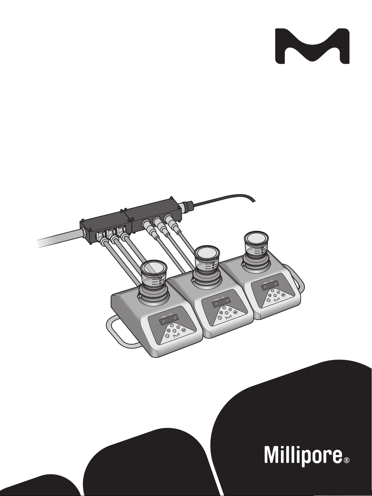
User Guide
Milliex® Plus
VHP Resistant Pump
The life science business of
Merck KGaA, Darmstadt, Germany
operates as MilliporeSigma in
the U.S. and Canada.
Millipore
ON
Millipore
VHP
OK
START
Millipore
VHP
OK
START
VHP
OK
START
C
OFF
C
ON
OFF
C
ON
OFF
Page 2

1. Notice
The information in this document is subject to change without notice and should not be construed as a
commitment by Millipore SAS. Millipore SAS assumes no responsibility for any errors that may appear in this
document. This manual is believed to be complete and accurate at the time of publication.
2. Application
The VHP Resistant Milliex® PLUS Pump is designed to perform ltrations of samples inside an isolator.
The pump is compatible with the isolator environment. The housing and the external parts are VHP resistant.
3. Operator and Equipment safety
All employees who will operate and/or be near the Milliex® Plus Pump VHP must comply with the following:
• Read and understand the user guide of the pump before
using this pump. Failure to follow operating instructions
could result in user injury or damage to the instrument.
• Read and understand all maintenance instructions
in this user guide before performing maintenance on
the pump. Failure to follow instructions could result
in user injury or damage to the instrument.
• Any alteration of the pump from factory specication
may cause unsafe conditions, and will void the
product warranty.
• Any attempt to use the pump in a manner not specied
in this user guide may result in damage to the instrument,
operator injury, and will void the product warranty.
• Do not attempt to open and repair the pump. Service
should be performed by trained and authorized
personnel only.
• Place the pump on a clean, at, stable, horizontal
surface, away from any source of excessive heat
and close to an easily accessible, properly grounded
power supply outlet.
• The Milliex® Plus Pump VHP must be installed and
used in a clean and dry area.
• The product is not intended to be used in explosive
atmosphere.
• Do not expose the power supply to liquid. If this
happens, immediately switch o and disconnect the
pump from the power outlet, wipe up the liquid.
• Use only accessories and replacement parts designed for
the pump. Using accessories not designed for the pump
could result in user injury or damage to the instrument.
• When ltrating hazardous liquids, wear and use proper
protective clothing and equipment for the handling and
the disposal of the liquid to be ltrated.
• The system power cord is the main system disconnecting
device, and must be easily accessible at all times.
• To avoid damaging the power cord or the outlet, it is
recommended that you pull on the plug and not on
the cord to unplug the system from a wall outlet or
an electrical connector.
• Make sure the power cord is not a tripping hazard. Make
sure that it is not gripped too tightly at the plug, the
outlet or the point where it is connected to the system.
• Before use, check that the hoses are not unplugged,
folded, or damaged.
• In case of skin contact with the ltrated liquid, refer
to the safety datasheet of the ltrated liquid for rst
aid measures.
• Dispose the ltrated liquids according to local regulations.
• Do not use the Milliex® Plus Pump VHP to ltrate
ammable products.
• Before cleaning, shut down the Milliex® Plus Pump
VHP and switch o and disconnect the power supply
from power source.
• Use only the power supply (model FRA072-S24-4)
designed for the pump.
• The power supply must be connected to the earthing
system.
• The electrical installation must comply with local
standards, power supply voltage: 100–240 Volt AC,
50–60 Hz.
• Use an electrical surge protector to prevent damage
to the system.
• Milliex® Plus Pump VHP System is designed for
indoor use only.
• Use and storage temperatures
– The Milliex® Plus Pump VHP and/or its accessories
must be kept away from any heat source. Do not
expose the system to direct sunlight or to temper atures outside the ranges of values are given below.
– Use and storage temperatures are given below:
System operation System storage Altitude
10 to 40 °C 0 to 40 °C < 2000 m
– Maximum relative humidity (storage and operation)
80% at temperatures up to 31 °C, then linear
decrease to 50% RH at 40 °C.
• System dismantling—WEEE directive:
In accordance with to the European Union
Directive 2012/19/EC on Waste Electric and
Electronic Equipment (WEEE), the presence
of this logo on the product indicates that it
should not be disposed of in the normal waste
stream but collected separately.
Go to millipore.com/weee for details on how to ensure
proper treatment of the product in dierent countries.
2
Page 3
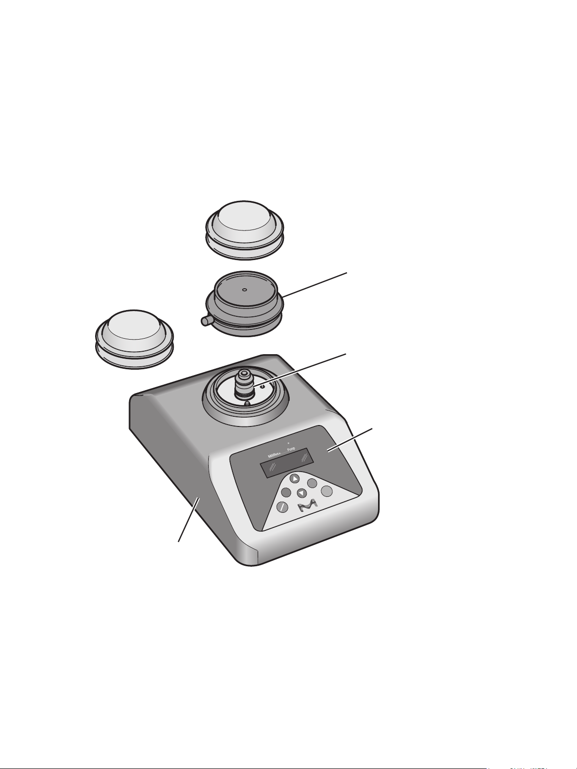
4. System description
A. VHP Pump (MXPPLUVHP)
The Milliex® Plus VHP pump is composed of the following elements:
• The pump body
• The pump head with its protective cover (MXPHEAVHP)
• A lead to protect the pump when the pump head is not in place (to be used for assembling the pumps
with the manifold tray)
VHP Resistant
Pump Head
Pump Head
Mounting Post
Control Panel
and Display
Millipore
VHP
OK
C
ON
OFF
START
Pump Body
The pump comes with the following documents:
• User Guide PF12640
• Certicate of conformity for the pump (MXPPLUVHPCOQ) and the pump head (MXPHEAVHPCOQ)
Note: The VHP resistant pump (MXPPLUVHP) is compatible with the VHP resistant pump head
(MXPHEAVHP) only. These items are designed for use with Milliex® ltration devices only.
3
Page 4

B. Manifold tray for VHP pumps (MXPTRAY03V2)
The manifold tray is used to assemble the pumps together.
C. Milliex® Plus pump VHP Hub kit (MXPHUBKIT)
The VHP Hub kit is composed of:
• Some components for the electrical parts: electrical hub, cables set and power supply
• Some components for the uidic parts: uidic hub and tubes set
MXPFHUVHP
Milliflex
®
fluidic hub
VHP compatible
MXTUBVHP—VHP
tubes set for Milliflex
fluidic hub
MXPELEHUB
Milliflex
hub VHP compatible
®
electrical
®
MXPELCVHP—VHP
cables set for Milliflex
electrical hub
MXPP0WVHP Electrical hub
power supply (with 1 power cord Eur
—1 power cord US)
®
4
Page 5
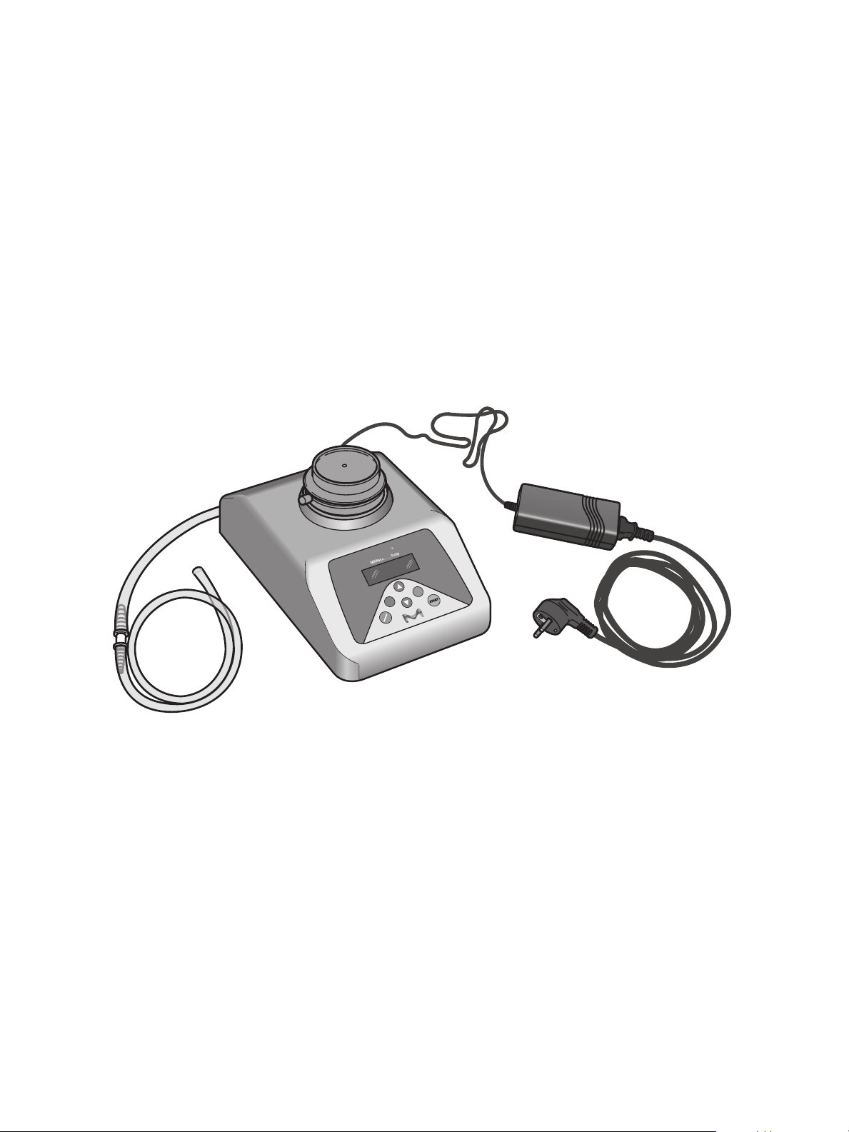
D. Supply set for one VHP Pump (MXPSPL001)
The supply set is composed of:
• A power supply
• A uidic tube
5. System installation
A. Single pump system
Connect the supply set (uidic tube and power cable) to the VHP pump as follows:
Then place the system in the isolator.
Millipore
VHP
ON
OK
START
C
OFF
5
Page 6
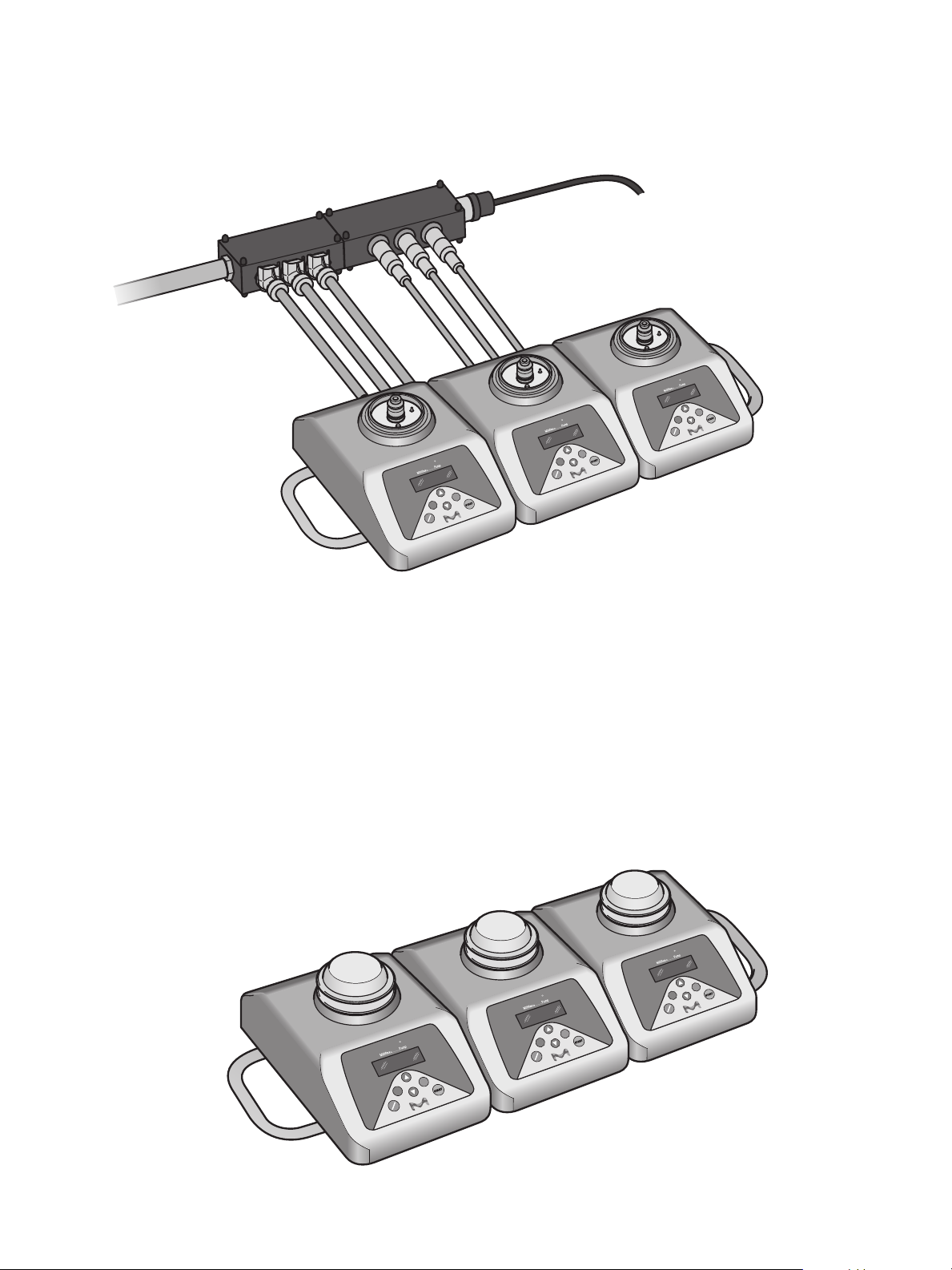
B. Three pump system
When using a three pump system, it is strongly recommended to assemble the pumps on the Manifold tray,
and to use the Hub kit for the electrical and uidic connections.
Millipore
VHP
OK
START
C
ON
OFF
Millipore
ON
Millipore
VHP
OK
START
VHP
OK
START
C
OFF
C
ON
OFF
It is recommended to assemble the pumps together before placing the system in the isolator. The use of
the tray facilitates the transfer of the assembled system to the isolator.
Caution: when assembled, the system is heavy (14.3 kg without the heads). Make sure you can handle the
system to transfer to the isolator.
1. Assembly of the 3 pumps on the tray
Do not place the pump head at this stage.
• Put the pump lead on each pump to protect them through the assembly step.
Millipore
VHP
OK
START
C
ON
OFF
Millipore
ON
Millipore
VHP
OK
START
VHP
OK
START
C
OFF
C
ON
OFF
6
Page 7
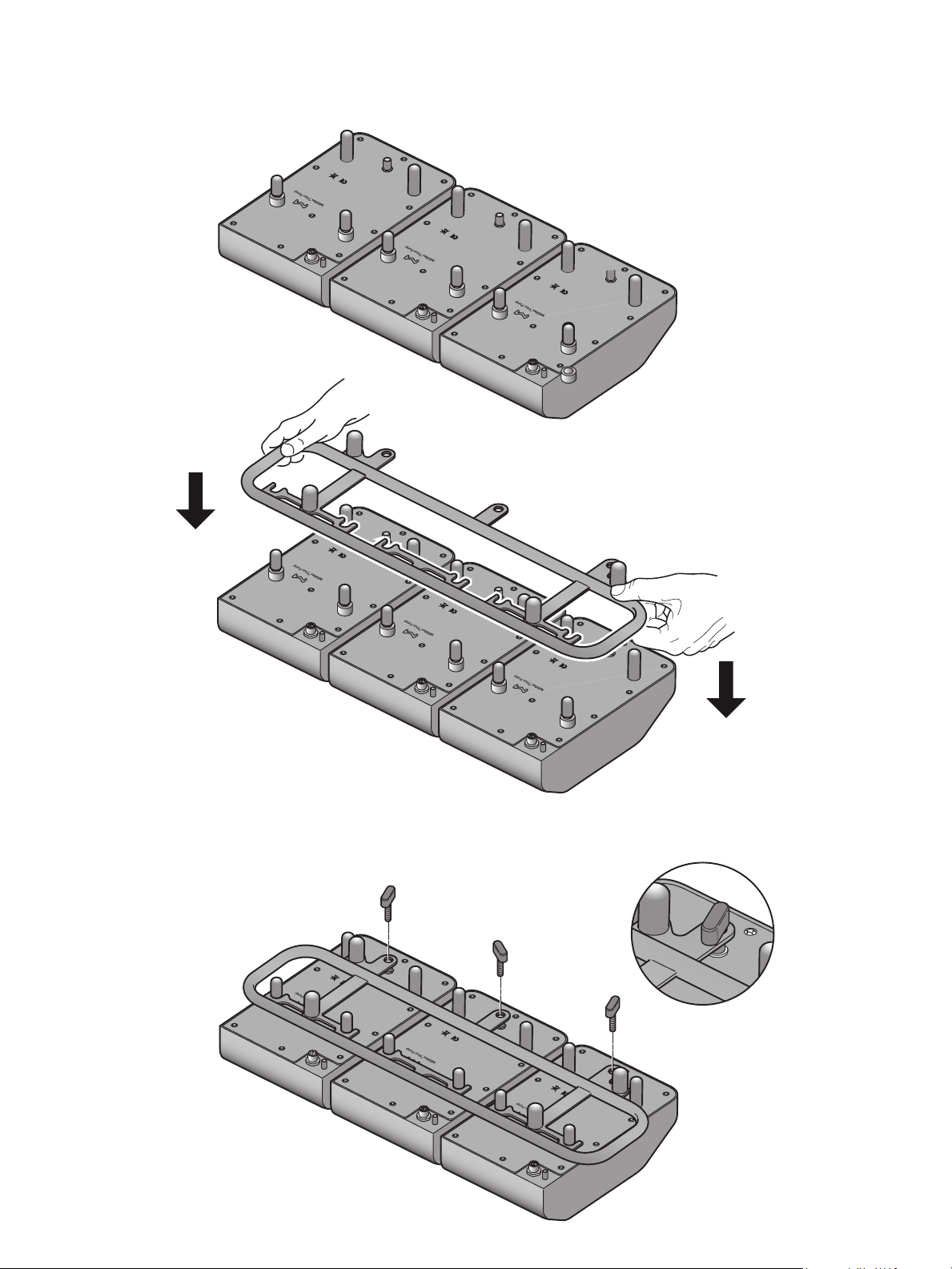
• Reverse the 3 pumps: the keypad should be facing the operator and the pumps should be aligned to
enable assembly with the tray
VHP Resistant
VHP Resistant
VHP Resistant
• Put in place the tray
VHP Resistant
VHP Resistant
• Fix each pump one by one to the tray using the fast screw
VHP Resistant
VHP Resistant
VHP Resistant
VHP Resistant
7
Page 8
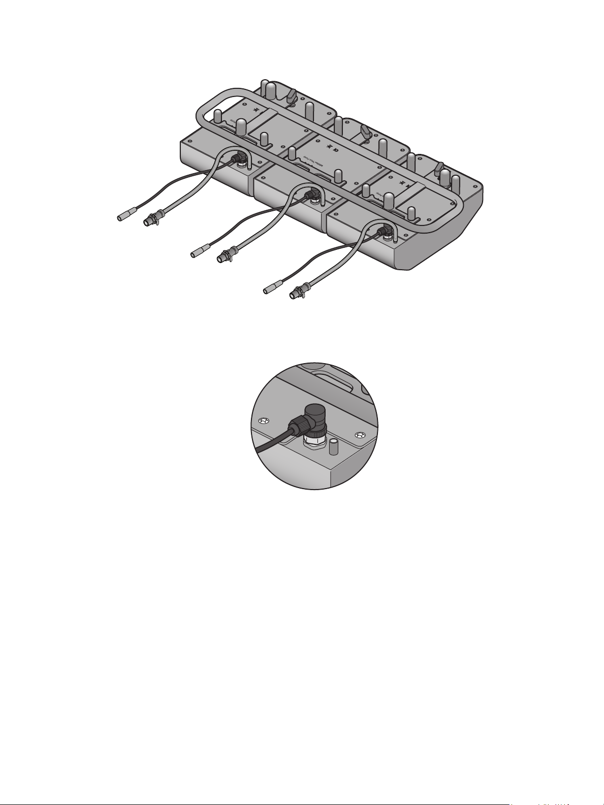
• Once the 3 pumps are assembled on the tray, connect the electric cables and uidic tubes to each pump
VHP Resistant
VHP Resistant
VHP Resistant
Detail of the electrical connection:
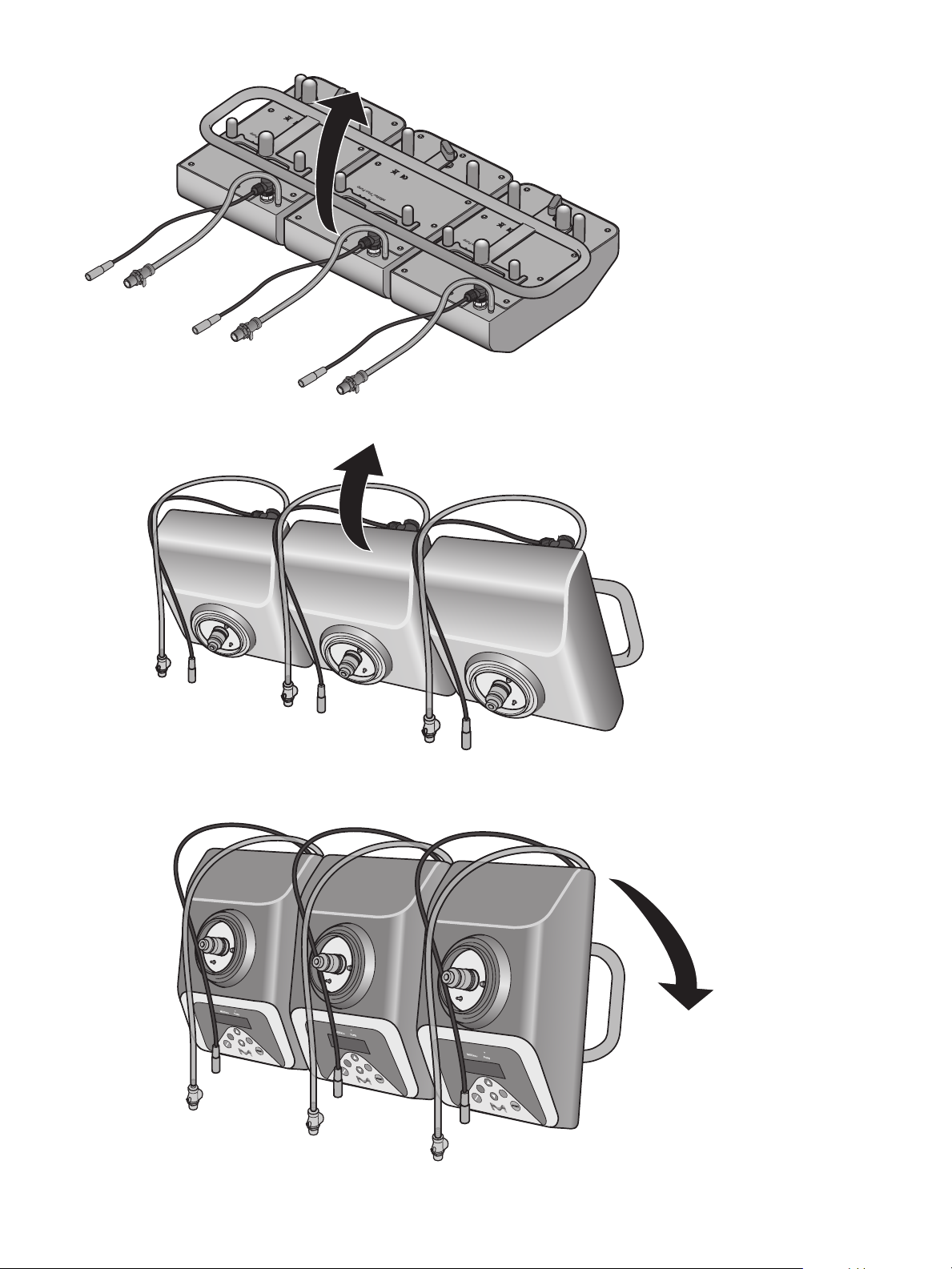
• Once all the connections are in place, reverse the whole system using the manifold tray. Take care not to
crush the uidic tubes and electric cables while reversing the system.
8
Page 9
1.
2.
VHP Resistant
VHP Resistant
VHP Resistant
3.
Millipore
ON
VHP
C
OK
OFF
START
Millipore
ON
VHP
C
OK
OFF
START
Millipore
ON
VHP
C
OK
OFF
START
9
Page 10
2. Hub installation
The VHP Compatible Milliex® PLUS Pump Hub is used to connect the uidic tubes and electrical cables from
up to three Milliex® PLUS pumps.
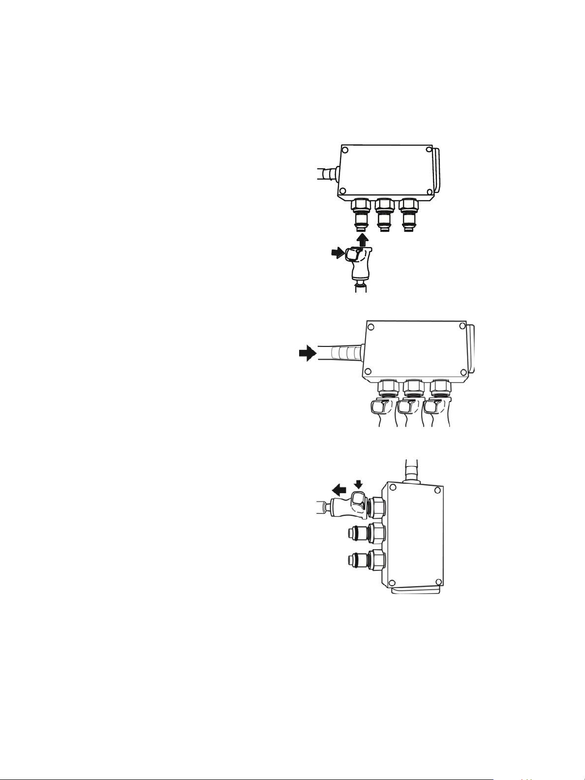
• Fluid Line Connections
Push the Milliex® PLUS Pump uid line connectors
into the uid hub until a click is heard. Install the
other end of the tubing onto the pumps.
Insert the output tubing onto the stainless
steel connector.
To disconnect the uid lines, push on the button
and pull the connector.
10
Page 11
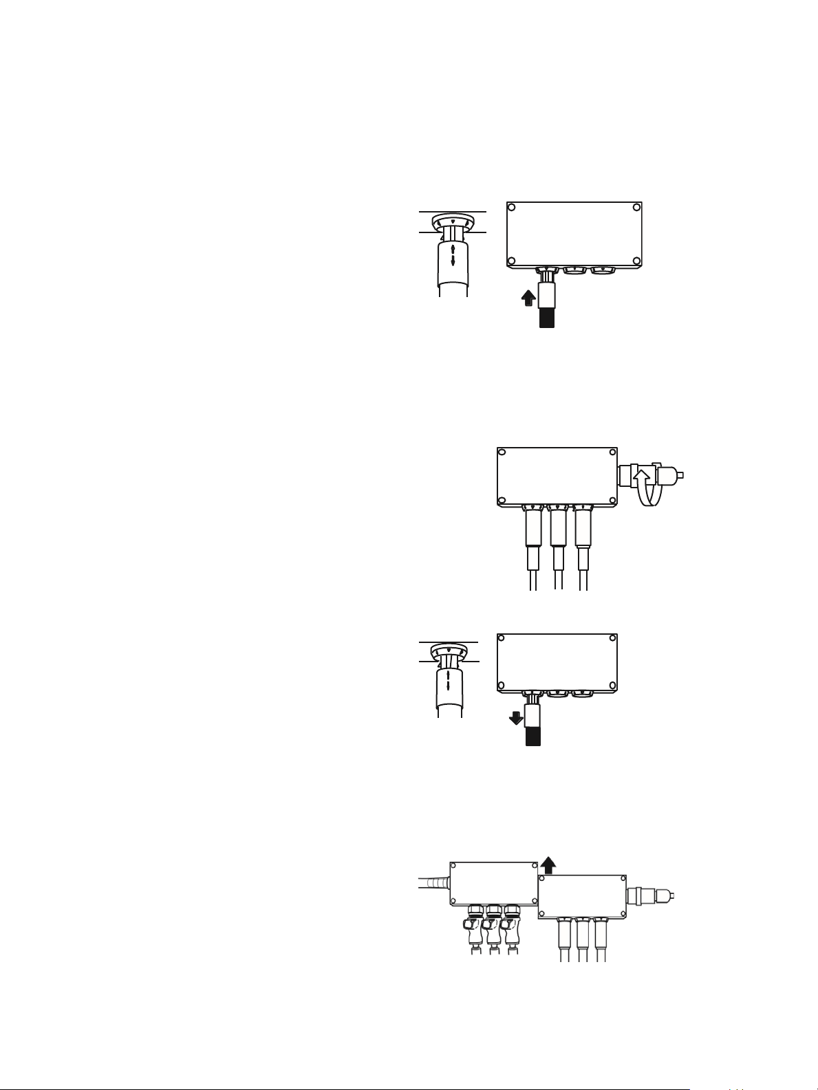
• Electrical Connection
Push the Milliex® PLUS Pump electrical cables into
the electrical hub until a click is heard. Connect the
other end of the cables onto the pumps.
Connect the power supply to the electrical hub and
tighten the connector.
To disconnect the electrical cables from the hub,
pull the cables out of the hub.
• Connecting the Hubs
The uid and electrical hubs may be connected or
disconnected by sliding them together.
11
Page 12
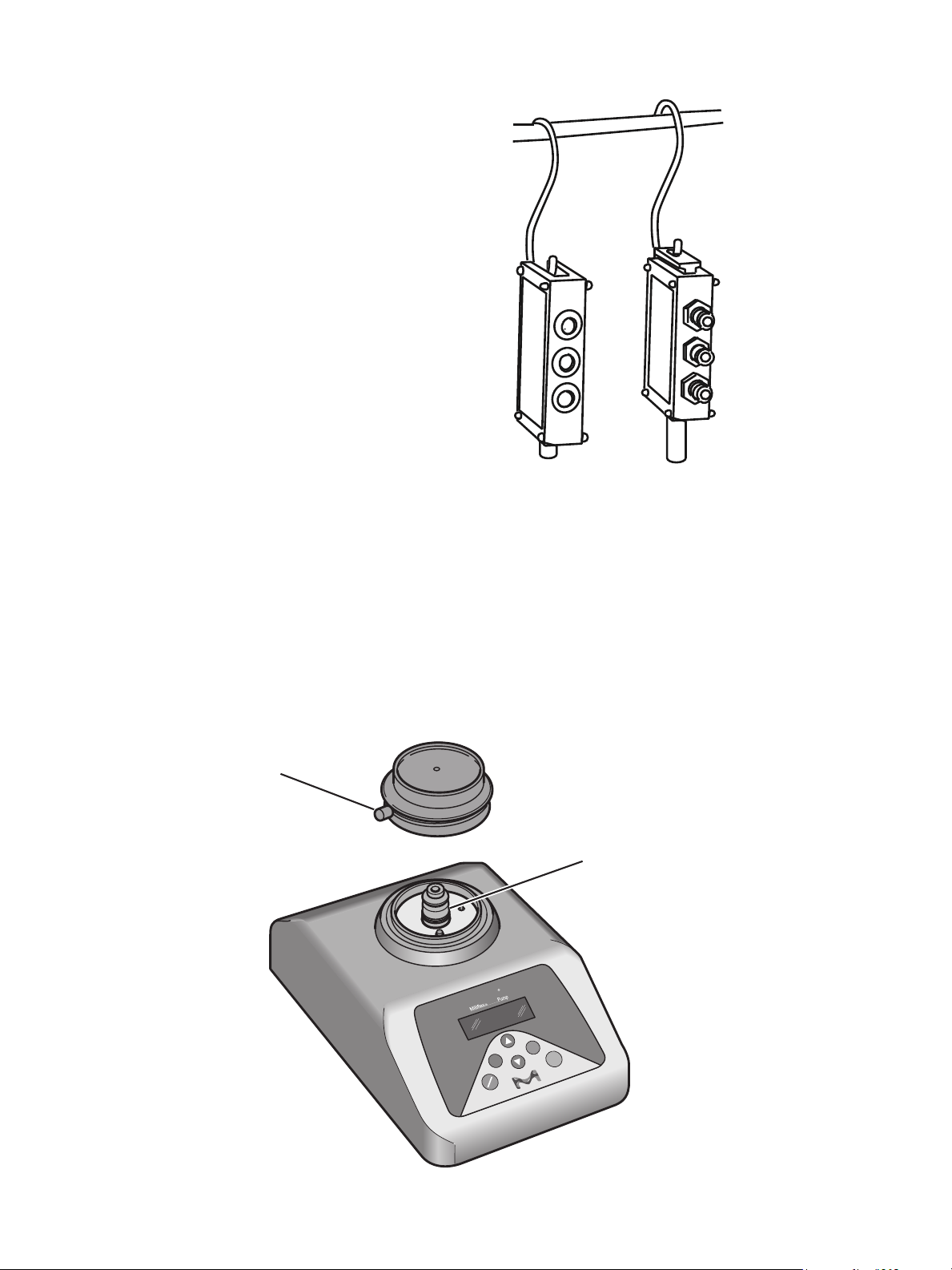
• Decontamination
The hubs must be cleaned after each use. To
decontaminate the uid line hub and the tubing,
use the sanitizing mode of the Milliex® PLUS Pump
(refer to the Milliex® PLUS Pump User Guide). The
external parts of both hubs may be sprayed with
an alcohol solution or a standard laboratory surface
decontamination solution.
Hang the hubs inside the isolator during the
decontamination cycle as shown below.
3. Pump head installation
• Push in the latch on the side of the pump head.
• Place the pump head onto the mounting post, with the latch to the left, as you face
the pump, as shown.
• Turn the pump head until it drops down and is fully in contact with the mounting post. The latch is
automatically released and locks the head in place. The latch should be positioned on the left side of
the pump assembly, when the head is locked in place.
NOTE: The pump head should be autoclaved before the rst use, as described in the Maintenance section.
Latch
Mounting Post
Millipore
VHP
OK
C
ON
OFF
START
12
Page 13
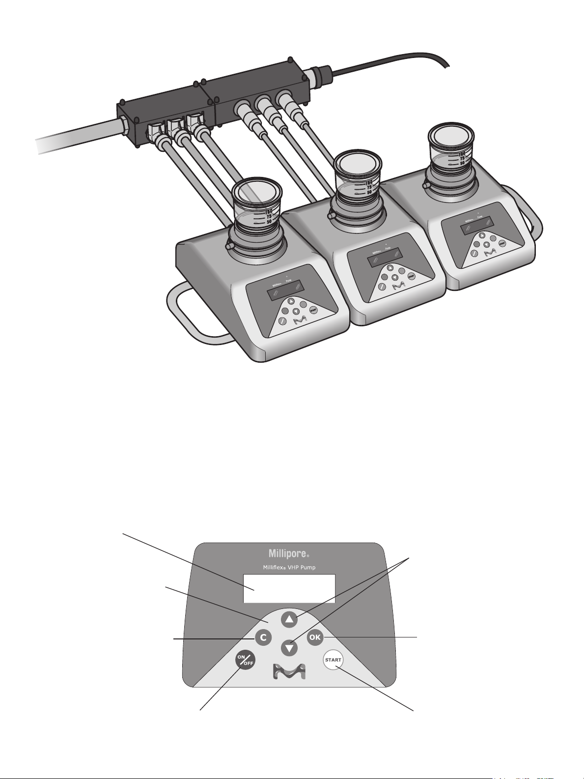
4. Typical installation
Millipore
VHP
ON
OFF
Millipore
VHP
OK
START
Millipore
VHP
OK
START
C
ON
OFF
OK
START
C
C
ON
OFF
Caution: the pump will not be VHP resistant if the O-ring or any screws are removed. The pump head must
remain in place on the pump during VHP cycle to maintain VHP resistance. The white cover delivered with the
pump head does NOT ensure VHP resistance of the pump.
6. Controls and display
A. Keypad
Display
Arrow buttons
(scroll through
Keypad control
C button
(cancel or return
to previous level)
selections)
OK button
(accept or go
to next level)
Power ON/OFF button
START button
13
Page 14
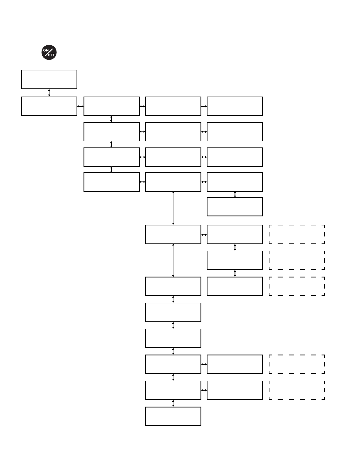
B. Control functions menu
POWER ON
Milliflex® PLUS
Serial N: xxx
Manual Tare
Sampling Manual Volume OFF
Sanitizing
Configuration Buzzer Buzzer ON
Remove expandable
press start
Place expandable
press start
Validation
See paragraph
8.B
See paragraph
8.D
Buzzer OFF
Weight
calibration
Time
verification
For maintenance
only
For maintenance
only
14
nber of cycle since
last calib: xx
nber of total
cycle: xx
Calibration date:
DD MM YY
Expendable
key number
Export
configuration
Software
V1.01 VHP
Vacuum
verification
Enter code
or press C
Connect printer
and press start
For maintenance
only
For maintenance
only
For maintenance
only
Page 15

7. Initial Power-up
At installation, the steps described above (Hardware Installation) should have been performed,
as applicable, before conguration.
1. Switch the pump on by pressing the ON/OFF button on the keypad. The display shows the
following for a few seconds: Milliex® PLUS SERIAL N:
2. The following display appears: Manual
3. Press OK. The display will show: Tare
4. Press OK. The display shows: Remove expendable—press start
5. Remove anything on the pump head (e.g., cover or disposable) and press START.
The display shows: measuring..... please wait......
6. After a few seconds, the display will revert to the display manual testing. (Additional information on
the Tare procedure may be found in the Preparation for Testing section.)
8. Operation
A. Preparation for Testing
We recommend that the pump head be autoclaved before the rst use and after each workday.
See the Maintenance section.
Whenever the pump head is removed, the Tare cycle must be run (see below).
It is also recommended to sanitize the pump interior before the rst use and after each workday, and
if the pump is unused for more than a day. See Sanitizing below, in this section.
1. Install the pump head, as described in the Installation section. Run the Tare cycle, as described below.
2. To prepare for testing, switch on the pump, by pressing the ON/OFF button on the keypad.
For a few seconds, the display shows: Milliex® PLUS Serial N:
After the power-up display, the Main Program Screen for the previously selected program is displayed.
For example: Manual
B. Tare
The Tare procedure adjusts the measurement system in the pump for the positioning and removing of
the Milliex® funnels
1. When the display shows Tare, press OK. The display shows: Remove expendable. Press Start
2. Remove anything on the pump head (e.g., cover or disposable) and press START. The display shows:
Measuring… Please wait…
After a few seconds, the display returns to the Main Program Screen for the previously-selected program.
C. Sample Processing
1. Position a tray of Milliex® 100 funnels with the Millipore name facing the operator.
2. Remove a funnel from its packaging tray. A notch in the tray is uncovered: this will facilitate picking
up the spacer.
3. Use sterile forceps to place the aseptic spacer on the pump head. Firmly press the funnel onto the pump head.
NOTE: Make sure that the base of the funnel is ush with the top of the pump head lter support.
4. Remove the cover from the funnel, while maintaining the funnel in position with the other hand.
15
Page 16

5. Pour a sample into the funnel, using the graduations to reach the required volume. When the required volume has
been reached, stop pouring. Leave the cover tilted on top of the funnel, but not closed, during the next two steps.
6. Press START to start the pump.
7. Operate the pump until the sample has been ltered, then press START to dry out the pump head.
Wait for the pump to stop.
8. Remove the white/opalescent cover from the solid cassette or the paper cover from the liquid cassette.
9. Remove the funnel from the pump head and reinstall the funnel cover.
10. Inspect the underside of the membrane, to verify membrane integrity. When viewed from beneath the funnel,
the membrane should have a convex shape.
11. Place the funnel base down over (and the lter membrane onto) the exposed medium cassette. The membrane
should be fully in contact with the medium.
12. Assure and secure membrane contact with the medium, by pressing slowly and rmly on the cover with the
thumb and forenger of each hand.
13. Press down on the top of the funnel with the palm of one hand. Start with a rm vertical pressure and
gradually increase your hand pressure until the funnel breaks o. The funnel will shear o at the groove on
the unit. NOTE: If the working position is uncomfortable, e.g., in a vertical laminar ow hood with the shield
in a low position, then the funnel may be broken in two steps, thus requiring less strength. Press slightly to
one side of the funnel rst, until a “snap” is heard, then press on the opposite side of the funnel until a
second “snap” is heard.
14. After the funnel section has broken o, remove the cover from the funnel and place it on top of the lter
cassette assembly.
15. Incubate upside down.
16. Wipe the pump head with an aseptic wipe.
D. Sanitizing
The pump interior should be sanitized before its rst use, after each workday and if unused for more than a day.
The Sanitizing cycle enables the user to sanitize the interior surfaces of the pump, according to a xed regimen.
See the Specications section for information on acceptable sanitizing agents.
The pump head can be autoclaved.
See the Maintenance section for autoclaving specications and for recommendations on cleaning the pump exterior.
In the Sanitizing cycle, the pump automatically circulates a quantity of sanitizing agent through the interior of
the uid-handling mechanism; pauses for ten minutes, while the interior surfaces are still wetted with the agent;
circulates the rest of the agent through the pump; and then circulates multiple rinses. The user is prompted to
add the appropriate liquid when required, at each stage. A drying cycle completes the process. The Milliex® HA
(mixed cellulose esters membrane) funnel should be used for sanitization with any recommended agent except
for solutions containing alcohol, where the Milliex® HV (PVDF membrane) is required. If the agent and the
membrane used are not compatible, remove the membrane from the funnel before sanitizing.
CAUTION
Install the exhaust tubing and waste receptacle higher than the pump, to prevent sanitizing agent being siphoned
out of the pump during the ten minutes of contact time.
1. At the Main Program Screen, press OK, to enter the Main Menu. The display shows: Tare
2. Press the down arrow until the display shows: Sanitizing
3. Press OK. The display shows: Put expendable—press start
4. Place an aseptic spacer and a Milliex® 100 funnel, without its cover, on the pump head and press START.
The display shows: Fill 100 mL of Agent press start
5. Fill the funnel with 100 mL of sanitizing agent and press START. The pump starts and the display shows: Sanitizing
16
Page 17

6. The pump should pull 25 to 75 mL of agent through (ltration during ve seconds); pause for ten minutes,
and then pull the remaining liquid through. A bar graph at the bottom of the display shows the progress of
this operation.
7. After the pump has emptied the funnel, it runs a drying cycle and then the display shows: Fill 100 mL of
Water press start
8. Fill the funnel with 100 mL of sterile water and press START. The display shows: Rinsing
9. The pump empties the funnel and runs a drying cycle. Then the display shows: Fill 100 mL of Water press start
10. Fill the funnel with 100 mL of sterile water and press START. The rinsing cycle is performed as before.
11. Then the display prompts for the funnel to be lled again, for each rinse, for a total of four rinses. When the
fourth rinse has been completed, the display shows: Sanitizing nished—Press start
12. Press START. Remove the funnel and discard it. The display shows: Sanitizing
13. Press C button to go back to the display manual testing. Remove the residual liquid on the Milliex® Head.
9. Maintenance
A. Autoclaving
Autoclave the pump head before the rst use and after the last use each day. Autoclave at 121 °C for 30 minutes,
or at 134 °C for 10 minutes.
B. Sanitizing
After each workday, or when the pump is unused for more than a day, sanitize the pump interior, using the
automated procedure provided in Sanitizing.
Sanitizing agents:
• Bleach 250 ppm
• Peraceticacid 0.125%
• Quaternary ammonium
C. Exterior Cleaning
The exterior surface can be cleaned with a soft cloth, moistened with alcoholic solution or a standard laboratory
surface alcohol decontamination solution
D. Calibration
Must be performed by our authorized internal Technician.
17
Page 18

10. System Specications
Materials of Construction
Dimensions
Electrical
Vacuum
Flow rate
TimeAccuracy
OperationalRequirements
Regulatory Information
Housing Stainless steel 316 L
Key pad Polyester
Screen window Polyester with coating
Drying valve o-ring Viton® elastomer
Liquid pump housing Polypropylene
Liquid pump membrane PTFE
Liquid pump valve Viton elastomer
Pump head Stainless steel 316 L with local Teon® coating
Fluidic connections Polyamide
Fluidic tubing Silicone
Pump head cover Polyacetal
Seal (O-ring between pump and pump head) EPDM
Bottom plate seal Silicone
Single 3 head system
Width 170 mm 585 mm
Depth 265 mm 265 mm
Height without head 162 mm 167 mm
Height with head 170 mm 175 mm
Weight without head 4.4 kg 14.3 kg
Weight with head 5.2 kg 16.8 kg
Power supply input 100–240 V — 50–60 Hz — 1.8 A
Power supply output 24 V VDC—3.0 A
Pump input 24 VDC
Pump power 25 VA
Electrical Hub 24 VDC/75 VA
≥ 0.4 bar (11.8 inches of Hg)
7 to 16 seconds for 100 mL of Milli-Q® grade sterile water ltered through a Milliex® MXHAWG124 funnel
± 2 seconds in 5 minutes
Temperature 10 °C to 40 °C (50 °F to 104 °F)
Relative humidity See chapter 3—Operator and Equipment Safety
Altitude < 2,000 Meters (6,561 feet)
Pollution degree II
Main supply voltage ± 10% of the nominal voltage
Transient over voltages Over voltage category II
Millipore SAS certies that the VHP Resistant Milliex® PLUS pump is designed and
manufactured in application of:
2014/30/EU Relating to electromagnetic compatibility
2014/35/EU Relating to electrical equipment designed for use within certain voltage
2011/65/EU Relating to the restriction of the use of certain hazardous substances (ROHS) in
electrical and electronic equipment
18
Page 19

11. Ordering Information
Catalogue No. Description Qty./Pk
MXPPLUVHP Milliex® PLUS Pump VHP Resistant 1
MXPHEAVHP Milliex® PLUS Pump Head VHP Resistant 1
MXPFHUVHP Milliex® Fluidic Hub VHP Compatible 1
MXPELEHUB Milliex® Electrical Hub VHP compatible 1
MXPTUBVHP VHP tubes set for Milliex® Fluidic Hub 3
MXPELCVHP VHP Cables set for Milliex® Electrical Hub 3
MXPP0WVHP Electrical Hub Power Supply 1
MXPTRAY03V2 Milliex® VHP Tray for 3 Pumps 1
MXPSPL001 Supply set for one Milliex® PLUS Pump VHP 1
FTPF01866 Power cord for Europe
FTPF02471 Power cord for North America, Central America Brazil Mexico
SIMCABLE1 Power cord for United Kigdom, Ireland, Malaysia, Singapore, Hong Kong
SIMCABLE2 Power cord for Denmark
SIMCABLE3 Power cord for India, South Africa
SIMCABLE4 Power cord for Switzerland
SIMCABLE7 Power cord for Japan
SIMCABLE8 Power cord for Australia, China, New Zealand, Argentina
SIMCABLE9 Power cord for Italy
Kits information
Kit No./Description Components Qty
MXPHUBKIT
Milliex® Plus Pump VHP Hub kit
MXPVHPKIT
Milliex® VHP 3 heads kit
MXPFHUVHP 1
MXPELEHUB 1
MXPTUBVHP 1
MXPELCVHP 1
MXPP0WVHP 1
MXPPLUVHP 3
MXPTRAY03V2 1
MXPFHUVHP 1
MXPELEHUB 1
MXPTUBVHP 1
MXPELCVHP 1
MXPP0WVHP 1
19
Page 20
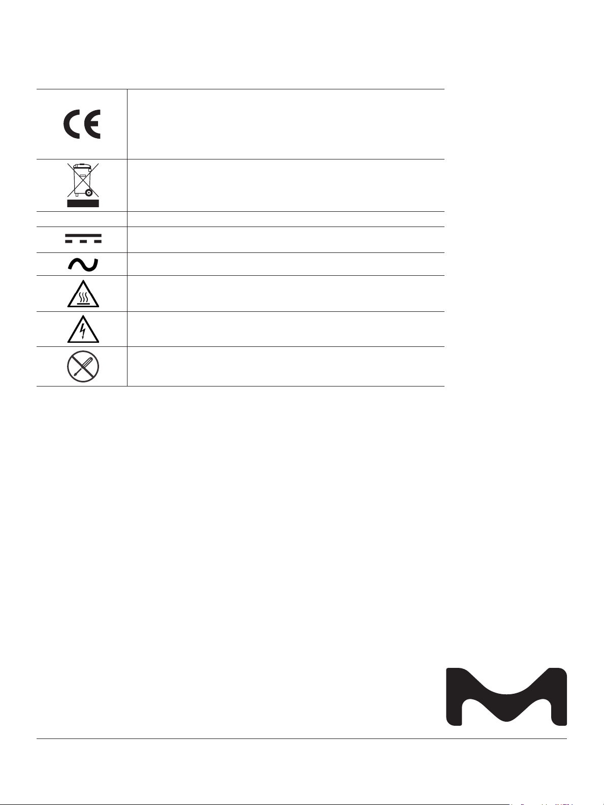
12. SymbolsReferenced
The presence of this logo on the product signies the compliance of VHP Resistant
Milliex® PLUS Pump with the following European Union directives:
2014/30/EU relating to electromagnetic compatibility
2014/35/EU relating to electrical equipment designed for use within certain voltage limits
2011/65/EU relating to the Restriction of the use of certain Hazardous Substances (RoHS)
in electrical and electronic equipment
In accordance to the European Union Directive 2012/19/EC on Waste Electric and
Electronic Equipment, the presence of this logo on the product indicates that it should
not be disposed of in the normal waste stream, but should be collected separately.
LPS
Go to Millipore.com/weee for details on how to ensure proper treatment of the in
dierent countries.
Indicates that the output voltage and current are limited.
Direct current (DC).
Alternate current (AC).
Hazard Hot surface.
Possible high-voltage hazard.
Do not disassemble.
13. Standard Warranty
The applicable warranty for the products listed in this publication may be found at
Millipore.com/terms (“Terms & Conditions of Sale”).
Manufacturer
Millipore SAS
39 Route Industrielle de la Hardt
67120 Molsheim, France
Technical Assistance
For more information, please visit Millipore.com/oces
for up-to-date worldwide contact information
© 2019 Merck KGaA, Darmstadt, Germany and/or its aliates. All Rights Reserved. The vibrant M, Millipore, Milliex,
Sigma-Aldrich, and Milli-Q are trademarks of Merck KGaA, Darmstadt, Germany or its aliates. All other trademarks are
the property of their respective owners. Detailed information on trademarks is available via publicly accessible resources.
PF12640 – Rev D
2017 - 08235
01/2019
 Loading...