

Page 1

Labscale
™
Tangential
Flow Filtration System
User Guide
Page 2

2 www.millipore.com
Notice
The information in this document is subject to change without notice and should
not be construed as a commitment by Millipore Corporation. Millipore Corporation
assumes no responsibility for any errors that may appear in this document. This manual
is believed to be complete and accurate at the time of publication. In no event shall
Millipore Corporation be liable for incidental or consequential damages in connection
with or arising from the use of this manual.
Page 3

Labscale Tangential Flow Filtration System User Guide 3
Contents
Introduction 5
Operator and Equipment Safety 5
Labscale Stirbase Setup 6
Module set up 6
Operating Requirements 7
System Overview/Unpacking Lists 8
Labscale TFF System 8
Labscale 500 mL Reservoir 9
Labscale Stir Base 11
Labscale Pump Module 12
Pellicon XL 50 Device 13
User Supplied Materials 13
Labscale TFF System Setup 14
Labscale 500 mL Reservoir Setup 16
Labscale Stir Base Set Up 19
Labscale Pump Module Set Up 21
Install Cleaning Tubing 25
Install Cleaning Tubing 25
Clean System 26
Drain System 27
Flush System 29
Flushing Device 30
Install Pellicon XL Device 30
Flushing 31
Drain System 33
Integrity Testing—Pellicon XL Device on System 33
Preconditioning 34
Concentration 35
Product Recovery 37
Dialtration—Vacuum 38
Shutdown 40
Cleaning Device 40
Clean System 40
Drain System 42
Flushing Device 42
Clean Base 42
Specications 43
Specications 43
Materials of Construction 43
ECComplianceCerticate 44
Page 4

4 www.millipore.com
Labscale TFF SystemOrdering Information 45
Labscale TFF system kit 45
Compatible pumps and pump head 46
Pellicon XL Devices 46
Labscale TFF System Maintenance 47
Labscale Stir Base Spare Parts 47
Labscale 500 mL Reservoir Spare Parts 47
Labscale Pump Module Spare Parts 49
PumpCheckValveFlushing 50
Diaphragm Pump Maintenance 51
Electrical Schematic 53
Labscale TFF SystemTroubleshooting 54
Electrical/Control 54
Performance 55
Pressure 56
Technical Assistance 58
Page 5
Labscale Tangential Flow Filtration System User Guide 5
Introduction
The Labscale TFF system is a simple, easy to use system, designed
specifically for the Pellicon® XL device. This modular system
includes a 500 mL acrylic reservoir with pressure gauges, device
docking manifold and retentate valve; system base with integral
magnetic stirrer and diaphragm pump. The design of this system
allows Millipore’s Pellicon XL device to dock directly onto the side
of the reservoir, making tubing connections short, minimizing
holdup and recirculation volumes.
Operator and Equipment Safety
Anyone operating or working near the Labscale system must be
aware of the following:
• Read and understand this Operators Manual before performing
maintenance on the system. Failure to follow instructions could
result in user injury or system damage.
• Read and understand all maintenance instructions in this operating
instruction manual before performing maintenance on the system. Failure
to follow instructions could result in user injury or system damage.
• Prior to operation, ensure the Labscale system is fully assembled
as described in Labscale TFF System Setup. Ensure all pumps and
sensors are properly conected to their connection ports on the system.
• Never operate the Labscale system in a hazardous environment or
use with flammable, combustible or solvent liquids.
• Any alteration of the Labscale system from factory specification
may cause unsafe conditions and will void the product warranty.
• Use appropriate power supply cable and fuses for the area where
the Labscale system is operated for information, see Labscale
Stirbase Setup.
Page 6

6 www.millipore.com
Labscale Stirbase Setup
• If you order the pump module separatly, ensure pump module
wiring connections are correctly installed, see Chapter “Labscale
Pump Module set up”.
Module set up
Risk of electric shocks
• Unplug power cord prior to opening the blank panel from system base.
• There are no user-serviceable parts inside the Labscale system.
• Service should be performed only by trained and authorized
personnel.
Risk of rupture
• Use caution when opening and closing valves. Failure to open or
close valves at the appropriate times could result in trapped high
pressure, product loss, damaged cassettes, chemical spills, and
pump damage. Carefully follow all operating instructions
• Prior to each use, carefully inspect all hoses and tubing for kinks
or restrictions that could result in pressure buildup and possible
rupture of hoses or tubing.
• Prior to each use, carefully check that tubing at pump outlet to feed
in port (FEED IN) and cleaning tubing are Sta-Pure (white) tubing.
Failure in correctly installing Sta-Pure (white) tubing can result in
overpressurized tubing and burst.
• Transfer pump tubing can rupture due to continuous contact
with moving parts. Follow tubing manufacturer’s recommended
replacement interval.
• Never move the system while there is liquid in the tank, while
system processes are running or the cassettes is in place.
Page 7
Labscale Tangential Flow Filtration System User Guide 7
• Never operate the system without the tank cover in place. Never
operate the system if any moving parts are exposed. Never operate
the system with the pump housing open.
• Use appropriate personal protective equipment, including eye
protection, when operating the system.
This equipment can potentially be used with biohazardous
products.
Operating Requirements
The system needs to be connected to electrical power and have
fuses installed to operate.
The Labscale system must only be uesd with the Millipore wall
transfomer provided and Millipore accessories.
Location Power Supply Reference
North America
Japan
115 VAC 50/60Hz, 1-phase XX42LSS11
Europe,
China
230 VAC 50/60Hz, 1-phase XX42LSS12
United Kingdom 230 VAC 50/60Hz, 1-phase XX42LSS13
Operating Conditions
The maximum operating altitude 2000 m
The over voltage category 2
The temperature operating range 40 to 25 °C (39 to 77 °F)
in a non-condensing
environment
Storage Conditions
The temperature storage range -10 C to 55 °C (14 to 131
°F) in a non-condensing
environment
Page 8
8 www.millipore.com
System Overview/Unpacking Lists
Labscale TFF System
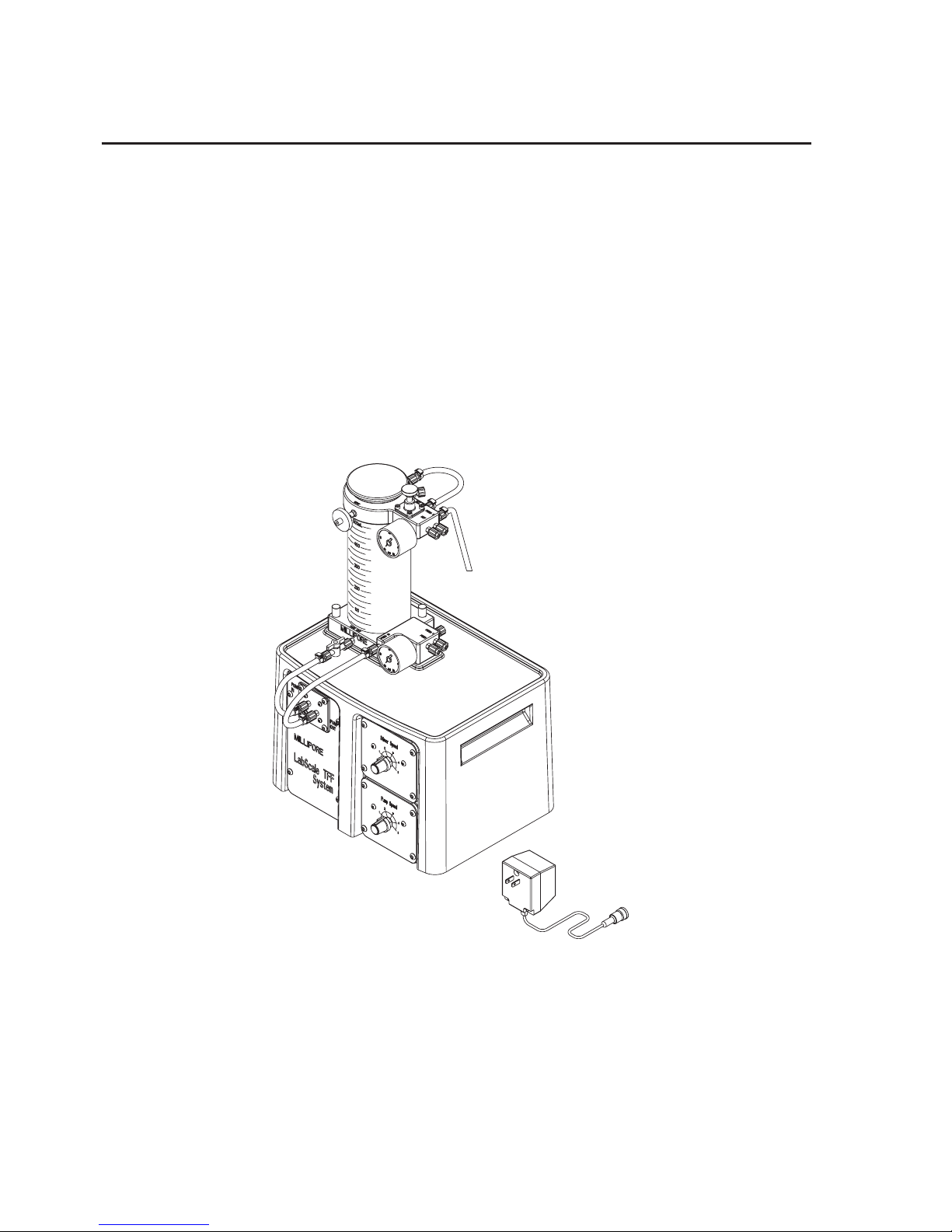
The Labscale TFF System is shipped in an overpack carton that
contains three separate cartons. One carton contains the Labscale
500 mL Reservoir, one contains the Labscale Stir Base with the
Labscale pump module installed, one contains the AC Adapter.
Figure 1: The Labscale TFF System, Catalog No. XX42LSS11(115V),
XX42LSS12(230V), XXL425513(230V GB).
Page 9
Labscale Tangential Flow Filtration System User Guide 9
Labscale 500 mL Reservoir
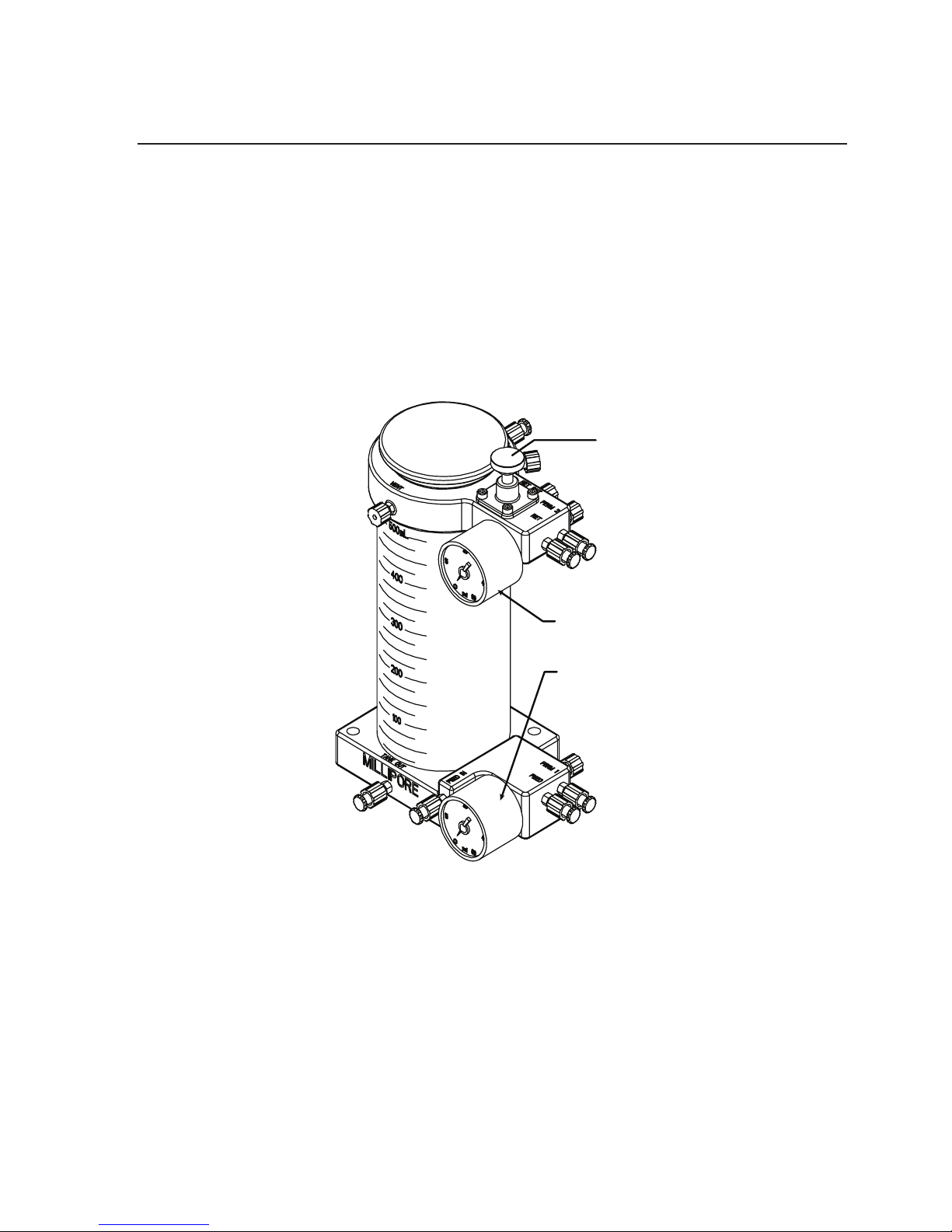
The reservoir manifold and instruments are an integrated system.
The feed pressure gauge indicates the pressure of the fluid being
pumped into the Pellicon XL device. The retentate pressure gauge
indicates the pressure of the fluid exiting the Pellicon XL device.
The upper manifold includes a retentate back pressure valve. The
fittings used are polypropylene and stainless steel.
Retentate Pressure Gauge
Retentate Back
Pressure Valve
Feed Pressure Gauge
Figure 2: Labscale 500 mL Reservoir, Catalog No. XX42RES01
Page 10
10 www.millipore.com
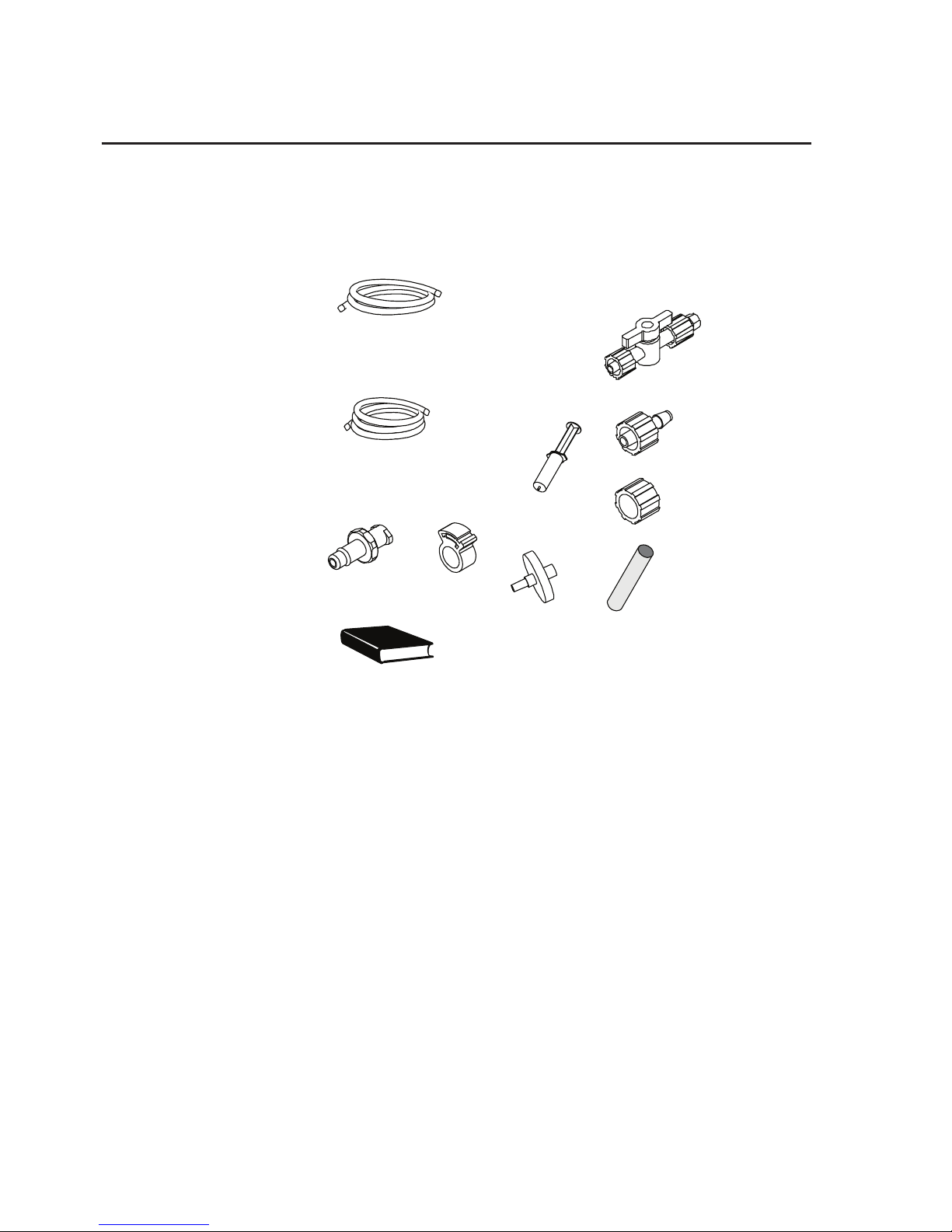
The following items are also packed with your Labscale 500 mL
Reservoir:
1 Shut-o Valve
10 Fittings
10 Fittings
10 Clamps
1 Syringe
1 Stir Bar
1 Millex
®
Vent
1 Operating Manual
3 Rotating
Lock Rings
6 feet (1.8 m) of Silicone
(translucent) tubing
1/8 in. (3 mm) ID
2 x 1 ft (0.3m) of Sta-Pure®
peristaltic pump tubing
1/8 in. (3 mm) ID.
Figure 3: Labscale 500 mL Reservoir Accessories
Page 11
Labscale Tangential Flow Filtration System User Guide 11
Labscale Stir Base
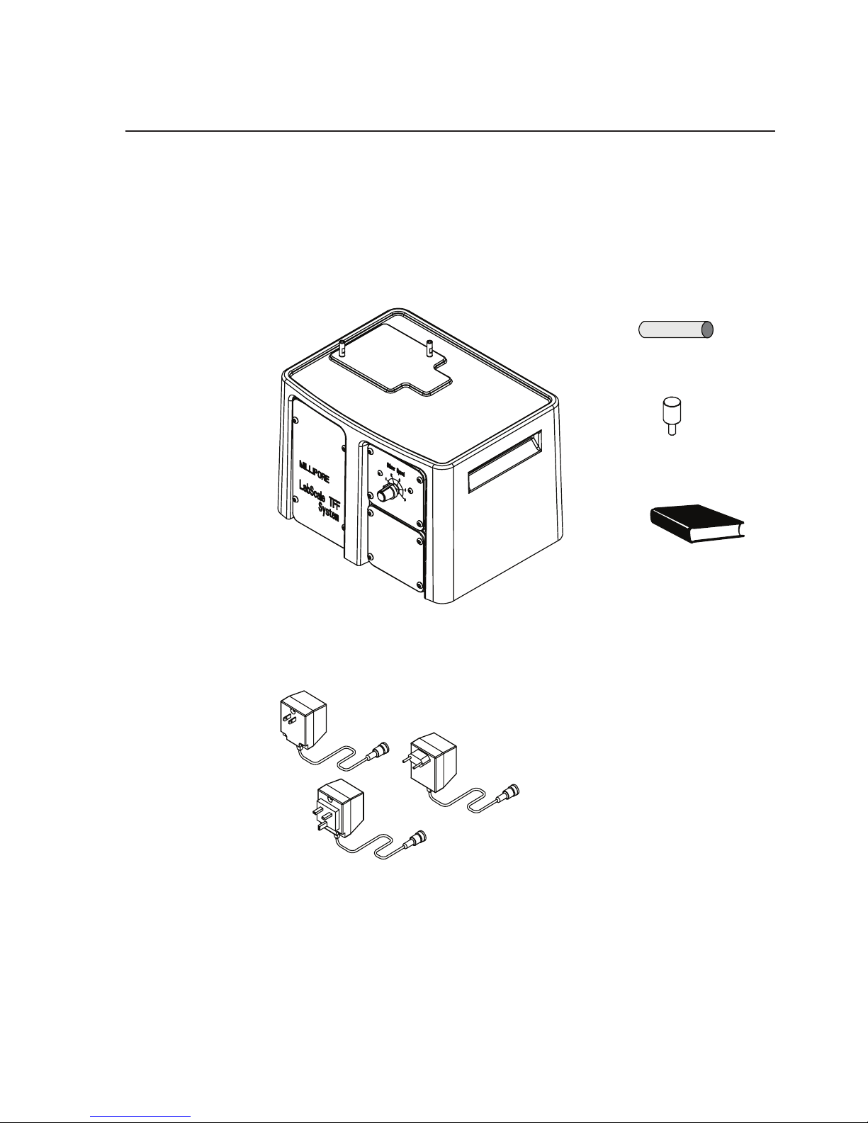
A magnetic stirrer is installed inside the base housing. A stir bar is
packed with the Labscale Stir Base unit. The speed control knob
for the stirrer is located on the front of the stir base.
1 Stir Bar
2 Thumbscrews
1 Operating
Manual
1 Stir Bar
2 Thumbscrews
1 Operating
Manual
Figure 4: Labscale Stir Base
Assembly No. 29755
1 Stir Bar
120 V
230V GB
230V
2 Thumbscrews
1 Operating
Manual
Figure 4b:Labscale Stir
Base Accessories
Figure 4c:AC Adapter Assembly No.
29209, (120V), 29781 (230V), 29913
(230V GB)
Page 12
12 www.millipore.com
Labscale Pump Module
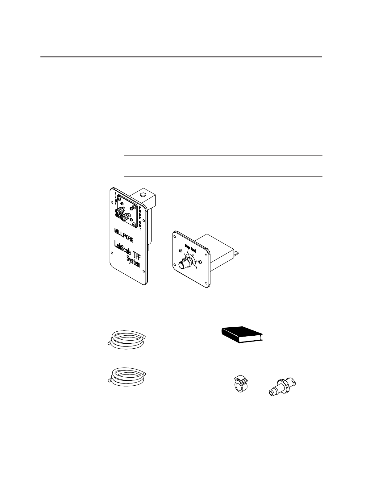
The Labscale Pump Module consists of a panel mounted electronic
diaphragm pump and a panel mounted speed controller that can
be installed in the Labscale Stir Base. The Labscale Pump Module
is mounted inside the base if a complete system was purchased. If
the pump unit was purchased separately, it is packed as shown in
figure 5.
Note: This Labscale Pump Module can only be used with the
Millipore Labscale Stir Base.
Figure 5: Labscale Pump Module Catalog No. XX42PMP01
4 clamps 4 ttings
4 clamps 4 ttings
1 Installation
Instructions
3 feet of Silicone
(translucent) tubing
1/8" (3mm) ID
1 x 1 ft (0.3m) of
Sta-Pure® peristaltic
pump tubing
1/8 in. (3 mm) ID.
Figure 6: Labscale Pump Module Accessories
Page 13

Labscale Tangential Flow Filtration System User Guide 13
Pellicon XL 50 Device
The Pellicon XL device is not included with the Labscale TFF
System. It must be purchased separately. The Pellicon XL device
includes an Accessories Kit that is packed in the Pellicon XL box
below the device. The parts in the accessory kit are not required
for this system installation.
User Supplied Materials
You will need to supply the following items for system setup:
suitable containers for retentate, permeate and waste collection,
scissors, a Pellicon XL Device.
Page 14
14 www.millipore.com
Labscale TFF System Setup
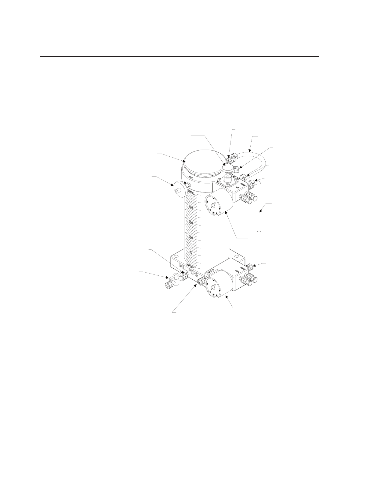
See “Labscale 500mL Reservoir Setup” section for detailed setup
instructions.
COVER
MILLEX VENT
FILTER
VENT PORT
FEED PRESSURE GAUGE
RETENTATE
PRESSURE
GAUGE
RESERVOIR
SHUT-OFF VALVE
TANK OUT PORT
FEED IN PORT
RET OUT PORT
PERM 2 OUT
PERM 1 OUT
RET IN PORT
RETENTATE TUBING
PERMEATE TUBIN
G
RETENTATE
BACK PRESSURE
VALVE
DIA RECIRC
Figure 7: Labscale 500 mL Reservoir set up.
Page 15
Labscale Tangential Flow Filtration System User Guide 15
COVER
MILLEX VENT
FILTER
VENT PORT
FEED PRESSURE GAUGE
RETENTATE
PRESSURE
GAUGE
RESERVOIR
SHUT-OFF VALVE
TANK OUT PORT
FEED IN PORT
RET OUT PORT
PERM 2 OUT
PERM 1 OUT
RET IN PORT
RETENTATE TUBING
PERMEATE TUBIN
G
RETENTATE
BACK PRESSURE
VALVE
DIA RECIRC
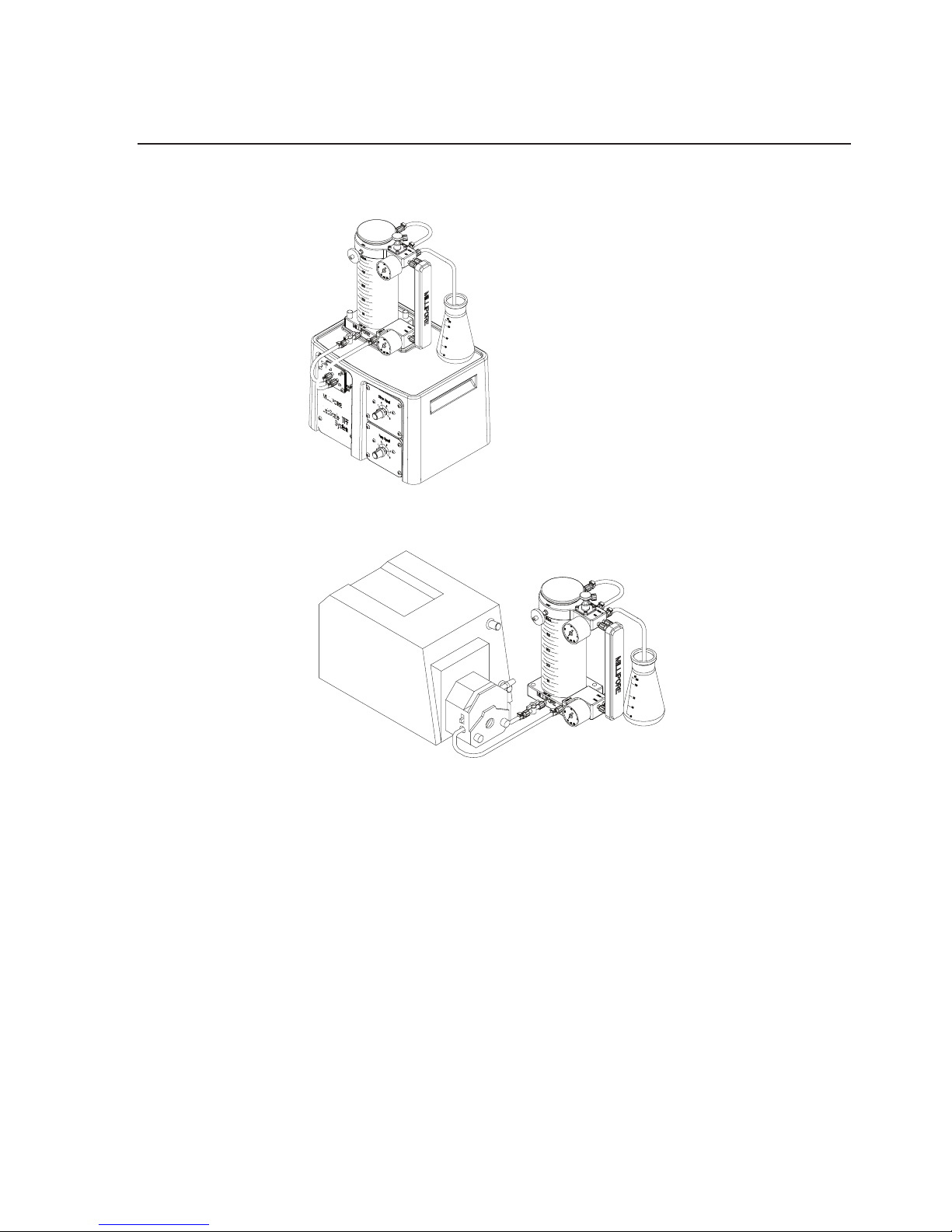
Figure 8: Labscale 500 mL Reservoir set up with Labscale TFF System.
FEED PRESSURE GAUGE
RETENTATE
PRESSURE
GAUGE
RET OUT PORT
PERM 2 OUT
PERM 1 OUT
RET IN PORT
RETENTATE TUBING
PERMEATE TUBIN
G
DIA RECIRC
Figure 9: Labscale 500 mL Reservoir set up with user supplied peristaltic
pump.
Install the Sta-Pure (white) tubing on the pump outlet and feed in
port of the reservoir.
Page 16
16 www.millipore.com
Labscale 500 mL Reservoir Setup
Note: All tubing lengths are recommended to minimize
recirculation volume. Longer lengths may be used.
After prolonged storage, the tubing may absorb a small
volume of water. As a result, the tubing color may
change from translucent to opaque, which is normal.
Air or oven drying will return the color to translucent.
Install Retentate Tubing
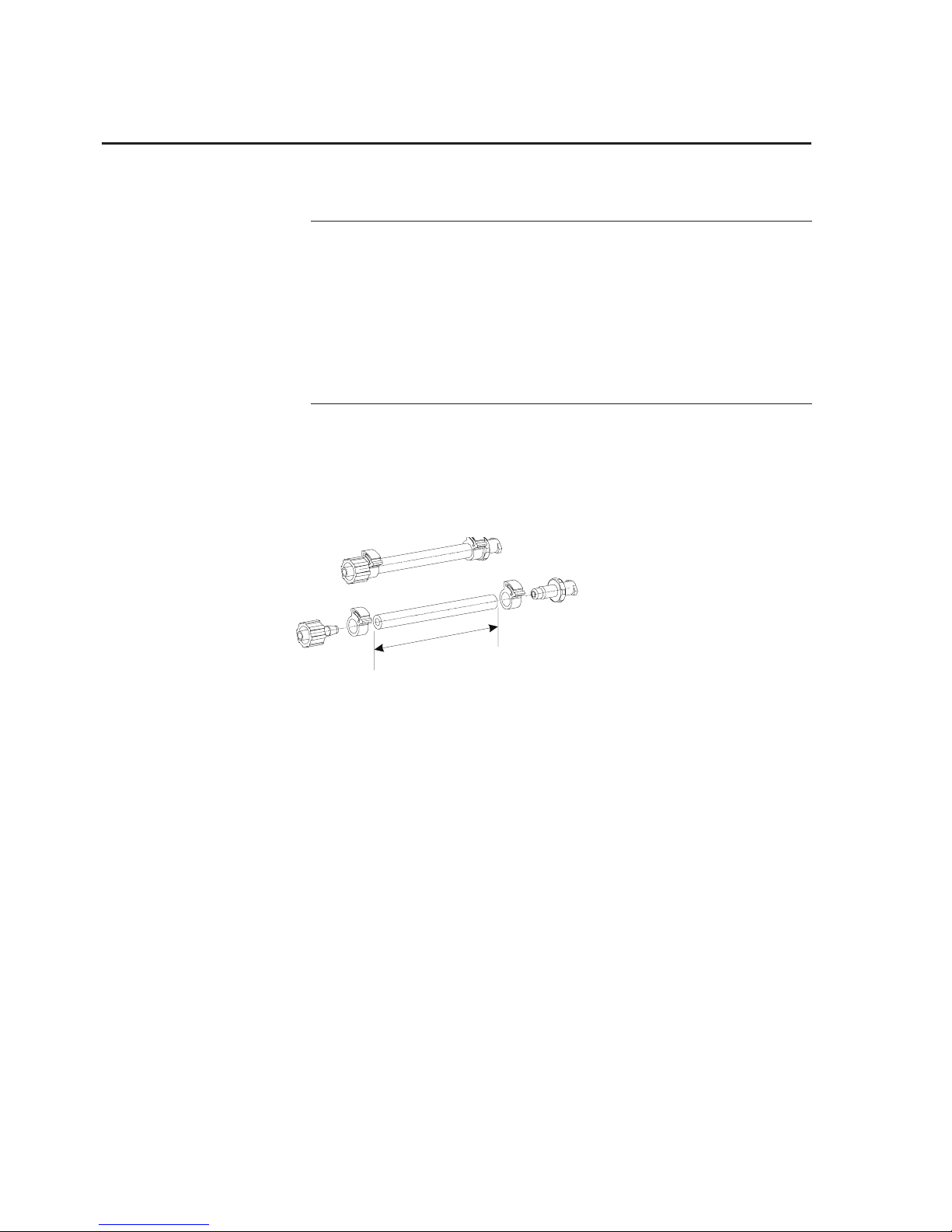
1. Cut silicone (translucent) tubing and install fittings as shown in
figure 10.
L = 15 cm (6 inches)
Fittings: 1 male, 1 female
MALE
FEMALE
L
Figure 10: Set-up of retentate tubing, ttings and clamps.
2. Remove plugs from retentate outlet (RET OUT) and retentate
inlet (RET IN) ports.
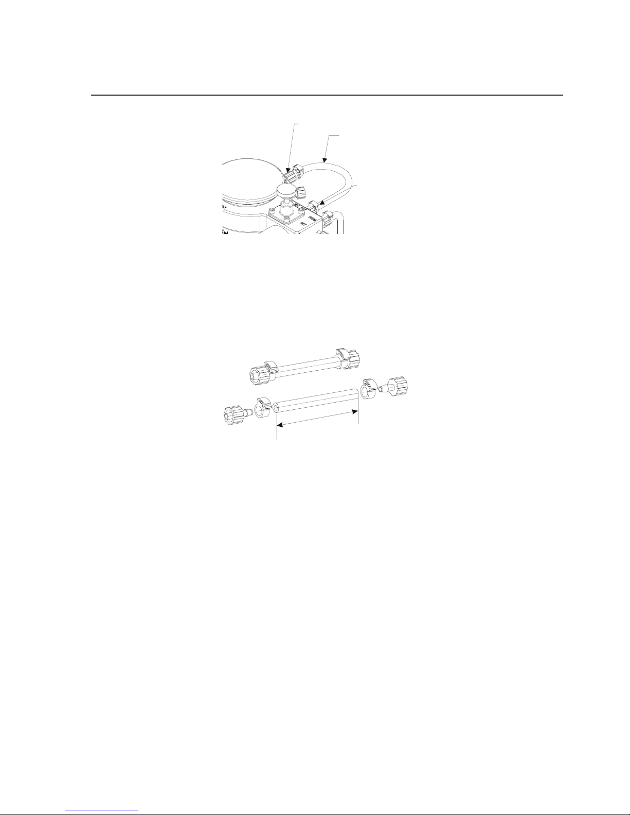
3. Insert the male luer end of the retentate tubing into the RET
OUT port and the female luer end of the retentate tubing into
the RET IN port. Turn fittings until snug.
Page 17
Labscale Tangential Flow Filtration System User Guide 17
L = 15 cm (6 inches)
Fittings: 1 male, 1 female
MALE
FEMALE
L
RET OUT PORT
RET IN PORT
RETENTATE TUBING
Figure 11: Install retentate tubing.
Install Permeate Tubing
1. Cut silicone (translucent) tubing and install fittings as shown in
figure 12.
L = 15 cm (6 inches)
Fittings: 1 male, 1 female
MALE
FEMALE
L
L = Appropriate length to reach
collection vessel.
Fittings: 2 male
MALE
MALE
L
RET OUT PORT
RET IN PORT
RETENTATE TUBING
Figure 12: Set-up of permeate tubing, ttings and clamps.
2. Remove the plug from the permeate outlet port (PERM 2) and
insert the male luer end of the permeate silicone (translucent)
tubing into the PERM 2 port. Turn fitting until snug.
Page 18
18 www.millipore.com
PERM 2 OUT
PERMEATE TUBIN G
Figure 13: Install permeate tubing.
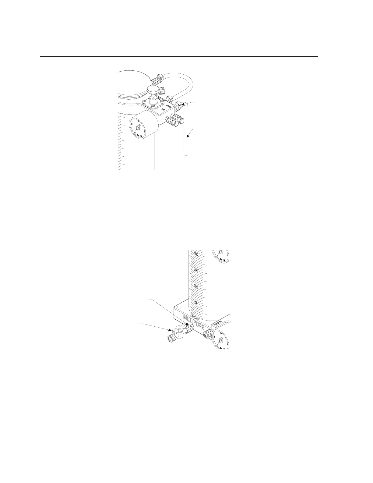
InstallTankOutletValve
Remove plug from the tank outlet port (TANK OUT) and insert
the female luer end of the tank outlet valve over the TANK OUT
port. Turn the lock nut until snug.
TANK OUTLET
VALVE
TANK OUT PORT
PERM 2 OUT
PERMEATE TUBIN
G
Figure 14: Install tank outlet valve.
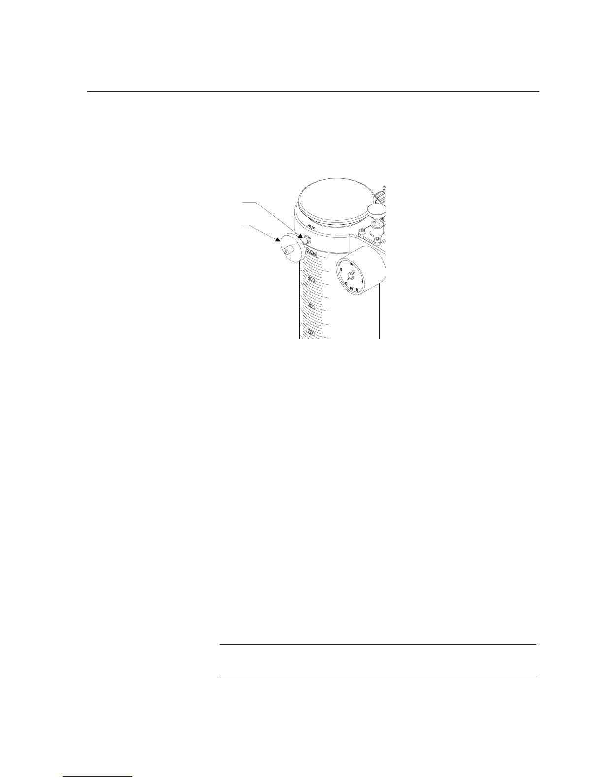
InstallVentFilter
If a sterile vent is required, remove plug from the vent (VENT) port
and insert male luer end of MILLEX filter into the VENT port.
Page 19
Labscale Tangential Flow Filtration System User Guide 19
Install Stir Bar
If mixing is required, open reservoir cover and drop stir bar to the
bottom of the reservoir.
MILLEX VENT
FILTER
VENT PORT
PERM 2 OUT
PERMEATE TUBIN
G
Figure 15: Install Millex vent.
Labscale Stir Base Set Up
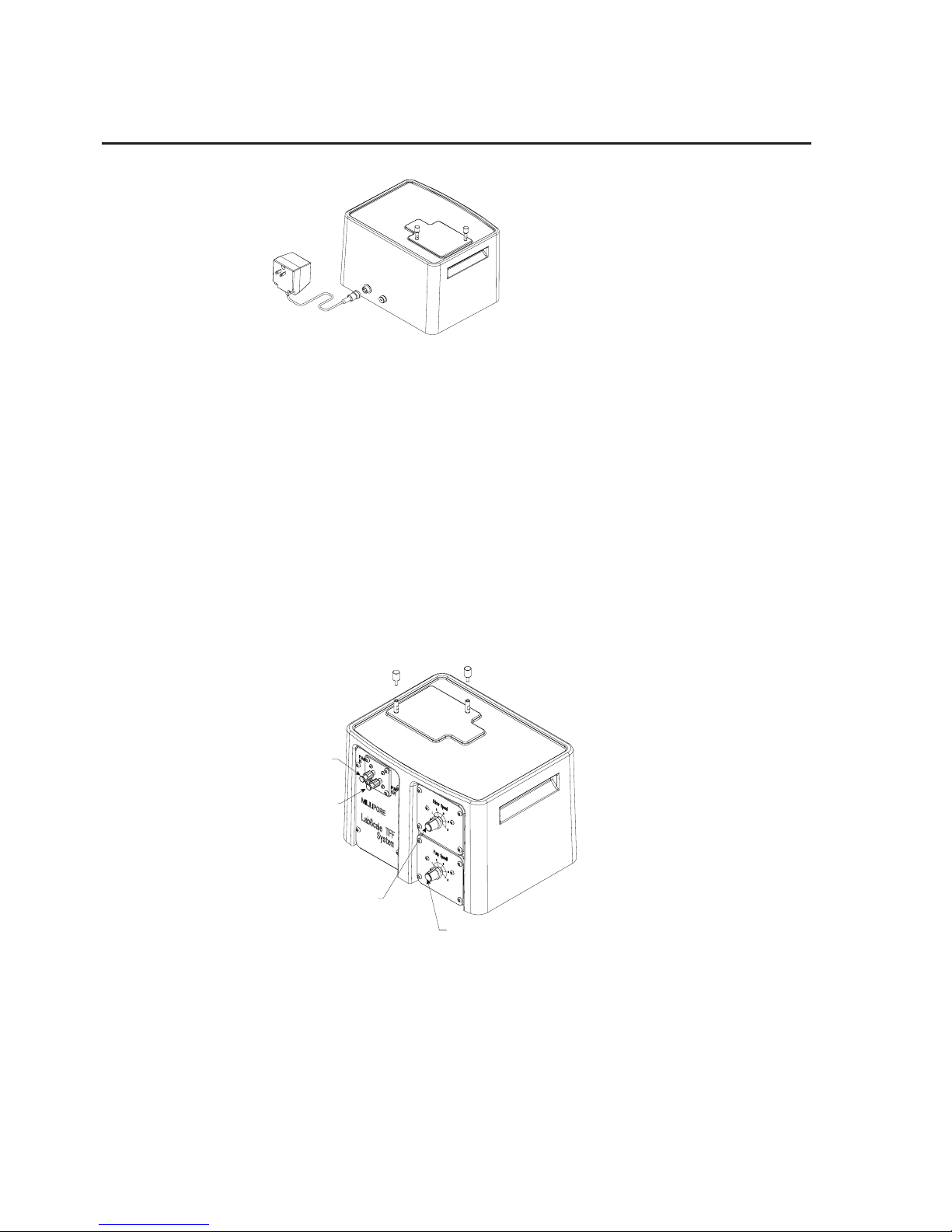
Power Connection
1. Turn stirrer and pump (if equipped) speed controls to the off
position.
2. Connect power cord to power cord receptacle located at the
rear of the system base.
3. Align detent on connector with receptacle.
4. Press connector into receptacle and turn lock ring to secure.
5. Inspect transformer label, checking for proper voltage. The
wall transformer serves as a means of cutting the power to the
system.
Note: The system should not be located in a place that may
allow liquid to be splashed under the enclosure.
Page 20
20 www.millipore.com
Figure 16: ower Connection
Check Operation
1. Remove the plugs from the pump inlet and pump outlet ports.
2. Turn on the pump speed control, set to 2, and listen for pump
motor.
3. Turn off the pump speed control.
4. Turn on the stirrer speed control, listen for the stirrer motor.
5. Turn off the stirrer speed control.
PUMP SPEED
CONTROL KNO B
STIRRER SPEED
CONTROL KNO B
PUMP INLET PO RT
PUMP OUTLET PORT
]
Figure 17: Check operation.
Page 21
Labscale Tangential Flow Filtration System User Guide 21
Labscale Pump Module Set Up
Labscale Pump Module Installation
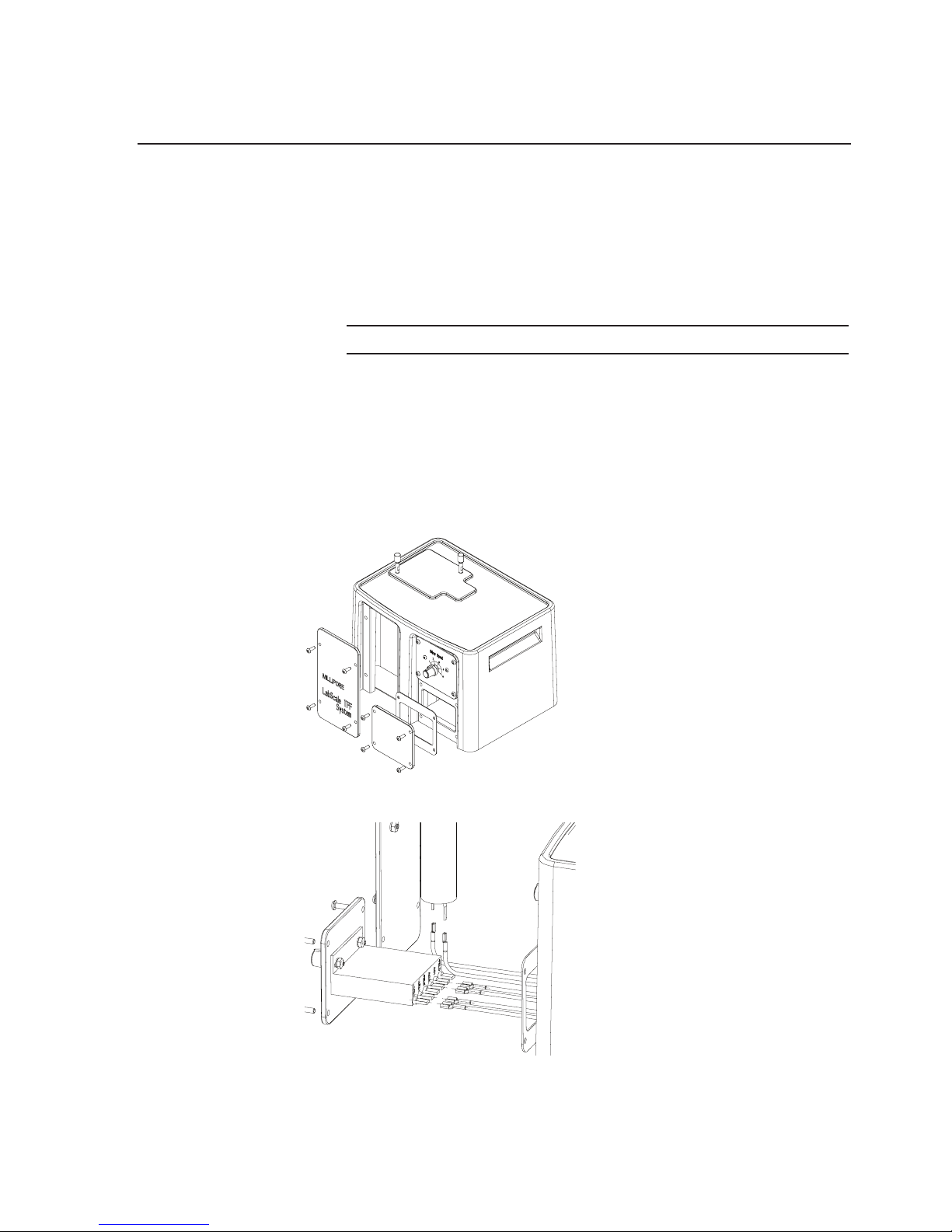
If you ordered the Labscale Pump Module separately, you will need
to install it in the Labscale Stir Base.
WARNING: Disconnect power connection before proceeding.
1. Remove the blank panels from the system base as shown in
figure 18.
2. Install gasket and make wiring connections as shown in figure 19.
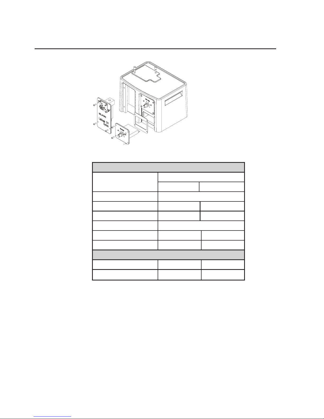
3. Secure the pump panel and pump speed control panel into the
base as shown in figure 20.
Figure 18: Remove blank panels from system base.
Figure 19: Labscale Pump Module wiring connections
Page 22
22 www.millipore.com
Figure 20: Labscale Pump Module installation
Speed Control
Connector
WIRE
Number Color
+ FIELD not used
AC1 1 Black
AC2 2 White
-FIELD not used
-ARM 6 Black
+ ARM 5 Red
Pump Control
+ 5 Red
- 6 Black
After prolonged storage, the tubing may absorb a small volume of
water. As a result, the tubing color may change from translucent to
opaque, which is normal. Air or oven drying will return the color to
translucent.
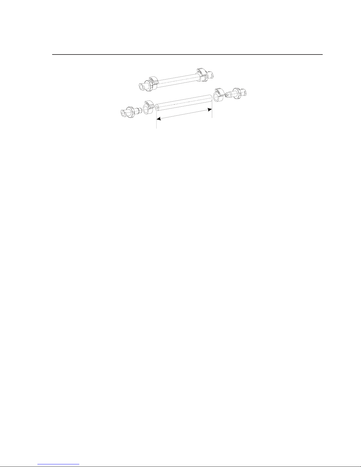
1. Cut silicone (translucent) tubing and install fittings and clamps.
Page 23
Labscale Tangential Flow Filtration System User Guide 23
L = 20 cm (8 inches) (cut 2)
Fittings: 4 female (2 per length)
FEMALE
FEMALE
L
Figure 21: Set-up of pump inlet and outlet tubing, ttings and clamps.
2. Cut one of the two Sta-Pure (white) tubing and install fittings
and clamps as shown in figure 21. Use only one Sta-Pure
(white) tubing for pump outlet. The other Sta-Pure (white)
tubing is used for cleaning.
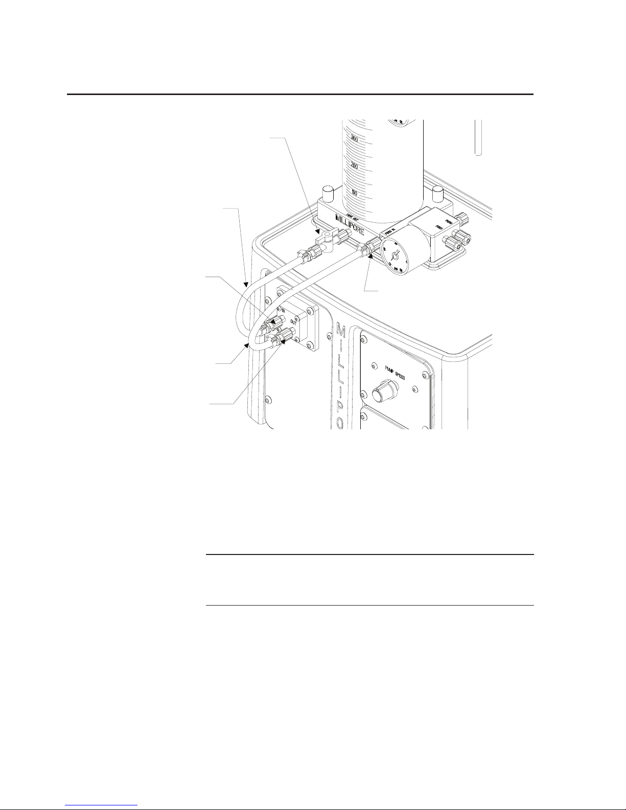
Install Pump Inlet and Outlet Tubing
1. Insert one female luer end of the silicone (translucent) tubing
over the PUMP INLET port and the other female luer end of
the silicone (translucent) tubing over the Tank Outlet Valve
and turn the lock nut until snug.
2. Insert one female luer end of the Sta-pure (white) tubing over
the PUMP OUTLET port and insert the other female luer end
of the Sta-pure (white) tubing over the Feed Inlet (FEED IN)
port and turn the lock nut until snug.
Page 24
24 www.millipore.com
L = 20 cm (8 inches) (cut 2)
Fittings: 4 female (2 per length)
FEMALE
FEMALE
L
PUMP INLET
TUBING
PUMP INLET
PORT
PUMP OUTLET
TUBING
PUMP OUTLET
PORT
FEED IN
PORT
TANK OUTLET
VALVE
Figure 22: Install pump inlet and outlet tubing.
INSTALLATION TIP:
To reduce pump pulsation, increase tubing length.
100mm (4 in) of additional tubing will only increase
fill volume by 0.8 mL.
Note: Failure to place Sta-Pure (white) tubing at the pump
outlet may result in overpressurized tubing and bursting
of tubing.
Page 25
Labscale Tangential Flow Filtration System User Guide 25
Install Cleaning Tubing
Install Cleaning Tubing
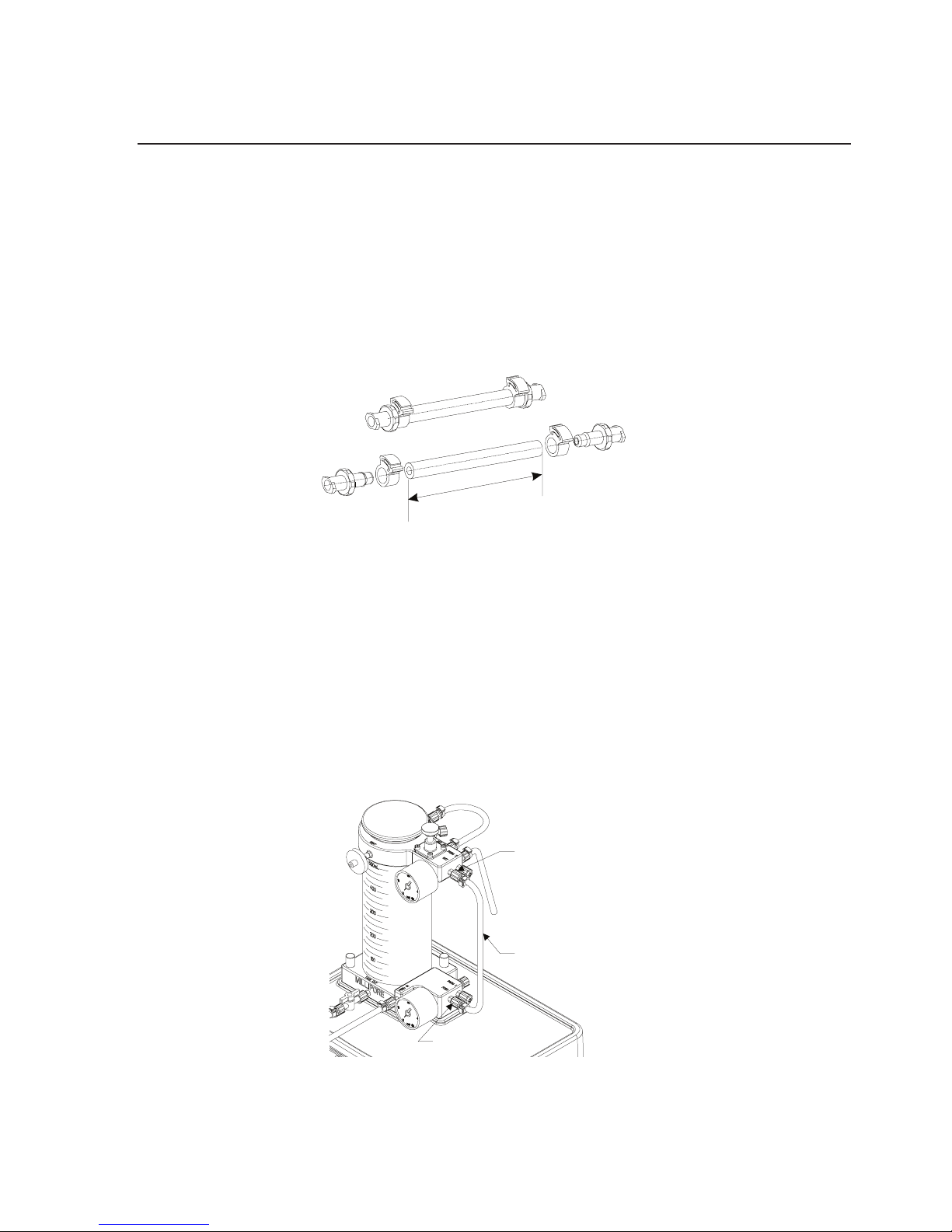
1. Cut Sta-Pure (white) tubing and install fittings and clamps as
shown in figure 23.
L = 25 cm (10 inches)
Fittings: 2 female
FEMALE
FEMALE
L
Figure 23: Setup of cleaning tubing, ttings and clamps.
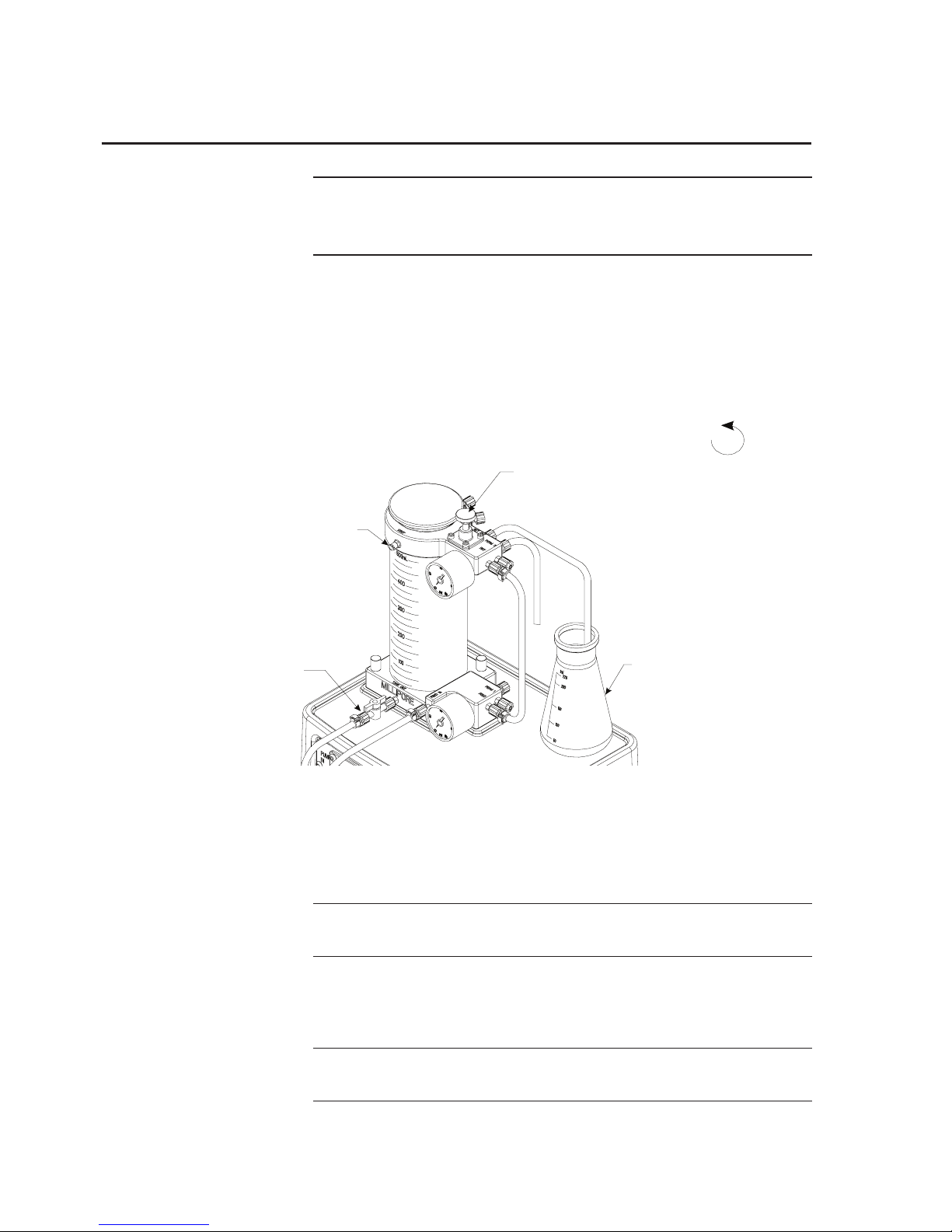
Remove the plug from the Device Feed port (FEED) and insert
one of the female luer ends of the cleaning tubing over the FEED
port. Turn the lock nut until snug.
2. Remove the plug from the Device Retentate port (RET) and
insert the other female luer end of the cleaning Sta-Pure
(white) tubing over the (RET) port. Turn the lock nut until snug.
L = 25 cm (10 inches)
Fittings: 2 female
FEMALE
FEMALE
L
CLEANING TUBE
DEVICE
RETENTATE PORT
DEVICE FEED PORT
Figure 24: Install cleaning tubing.
Page 26
26 www.millipore.com
Note: Failure to place Sta-Pure (white) tubing at the pump
outlet can result in overpressurized tubing and bursting
of tubing.
Clean System
1. Disconnect retentate silicone (translucent) tubing from RET
IN port and place in waste collection vessel.
2. Open retentate valve by turning counterclockwise
.
L = 25 cm (10 inches)
Fittings: 2 female
FEMALE
FEMALE
L
RETENTATE
BACK PR ESSURE
VALVE
VENT PORT
WASTE COLLECTION
VESSEL
TANK OUTLET
VALVE
CLEANING TUBE
DEVICE
RETENTATE PORT
DEVICE FEED PORT
Figure 25: System Cleaning steps 1–6
3. Remove reservoir cover and fill reservoir with 500 mL of 0.1N
Soduim Hydroxide at 45 °C.
Note: Follow solution manufacturer.s directions for proper
handling.
4. Remove plug from VENT port and open tank outlet valve.
5. Turn pump on - set pump speed to 2.
Note: Check system connections for leaks—tighten connec-
tions if required
Page 27
Labscale Tangential Flow Filtration System User Guide 27
6. Continue pumping the cleaning solution to the waste
collection vessel until the level in the reservoir drops to 250
mL. Turn pump off.
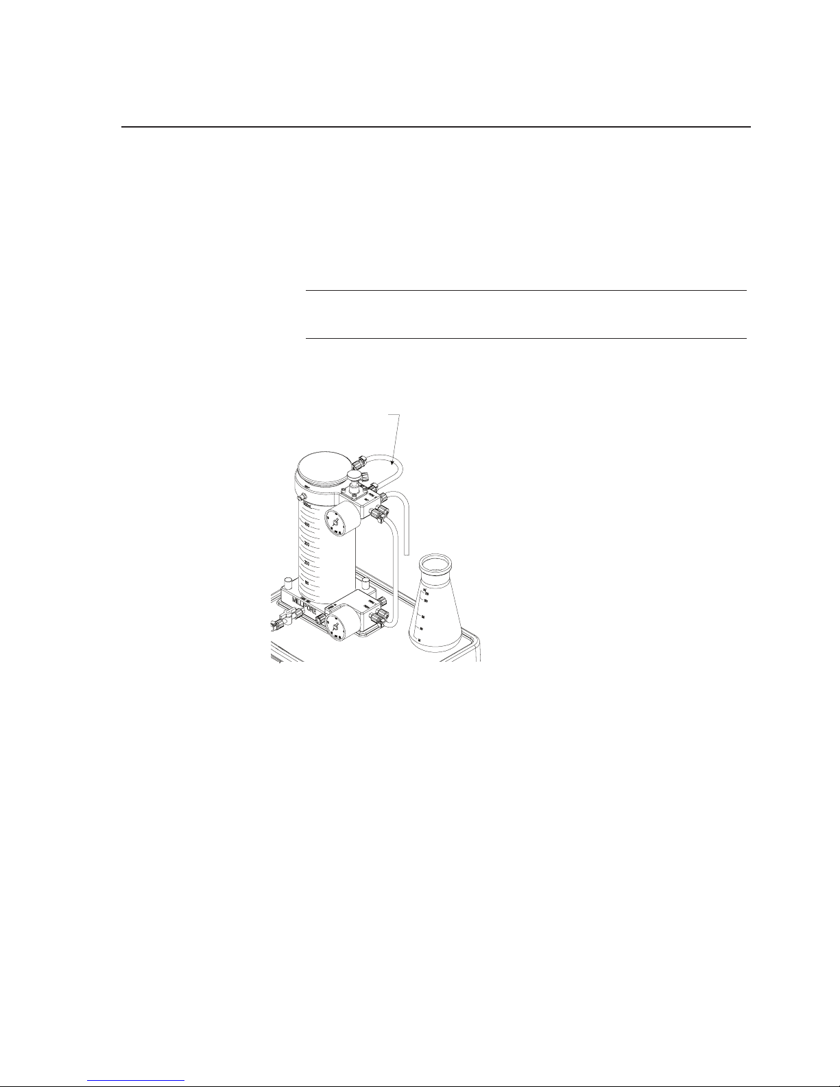
7. Reconnect the retentate silicone (translucent) tubing to the
RET IN port. Turn pump on and set pump speed to 2.
Note: Check system connections for leaks—tighten connec-
tions if required
8. Set pump speed to 2. Recirculate for 15–30 minutes. Turn
pump off.
RETENTATE TUBING
Figure 26: Setup for system cleaning steps 7 & 8
Drain System
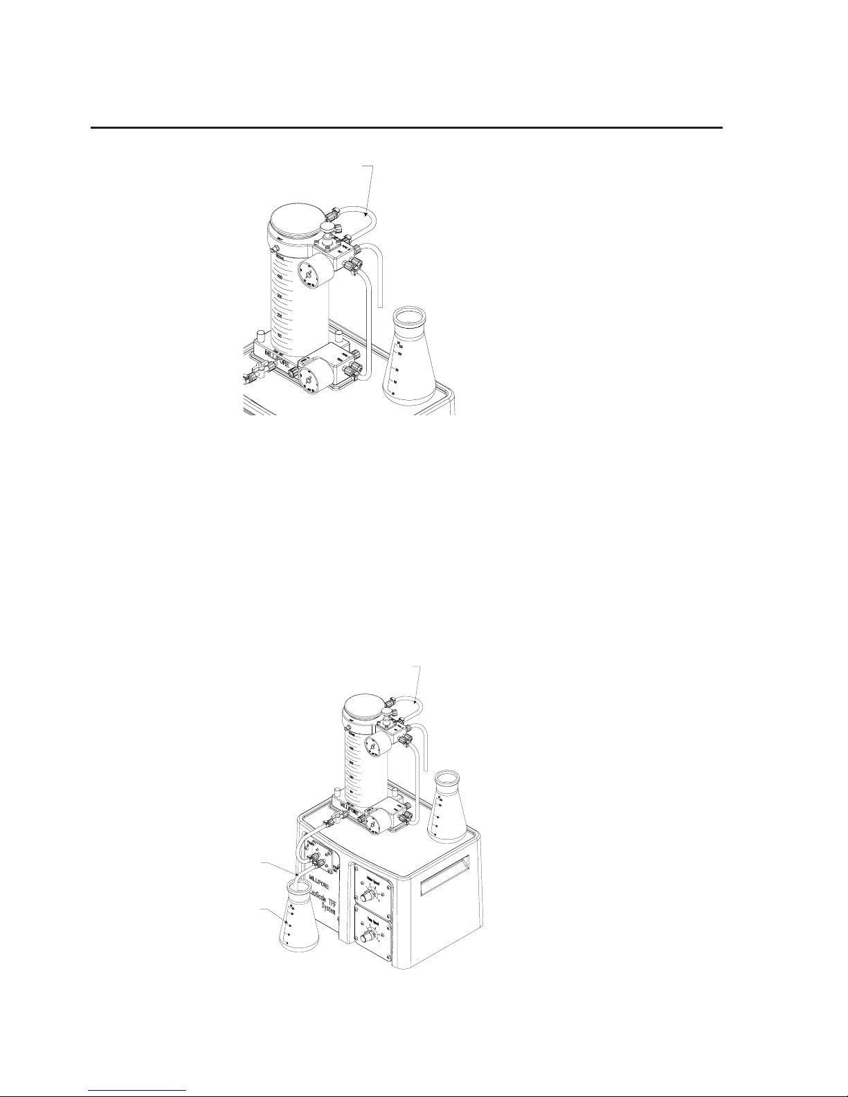
1. Disconnect pump outlet Sta-pure (white) tubing from pump
outlet port and place in waste collection vessel.
2. Disconnect retentate silicone (translucent) tubing from RET
IN port. Fluid should now drain by gravity. If additional
drainage is required, a syringe can be placed on the end of the
retentate tube and fluid can be blown down.
Page 28
28 www.millipore.com
RETENTATE TUBING
Figure 27: Setup for system draining steps 1 and 2.
3. Replace retentate silicone (translucent) tubing in retentate port.
Reconnect pump outlet Sta-Pure (white) tubing.
4. Disconnect pump outlet Sta-Pure (white) tubing from FEED
IN port and place in collection vessel. Open tank outlet valve,
turn pump speed up to drain reservoir.
5. Reconnect the pump outlet Sta-Pure (white) tubing to the
FEED IN port.
RETENTATE TUBING
PUMP OUTLET
TUBING
COLLECTION
VESSEL
Figure 28: Setup for system draining steps 3–5.
Page 29

Labscale Tangential Flow Filtration System User Guide 29
Flush System
Repeat instructions for System Cleaning substituting purified water
in place of cleaning solution.
Page 30
30 www.millipore.com
Flushing Device
Install Pellicon XL Device
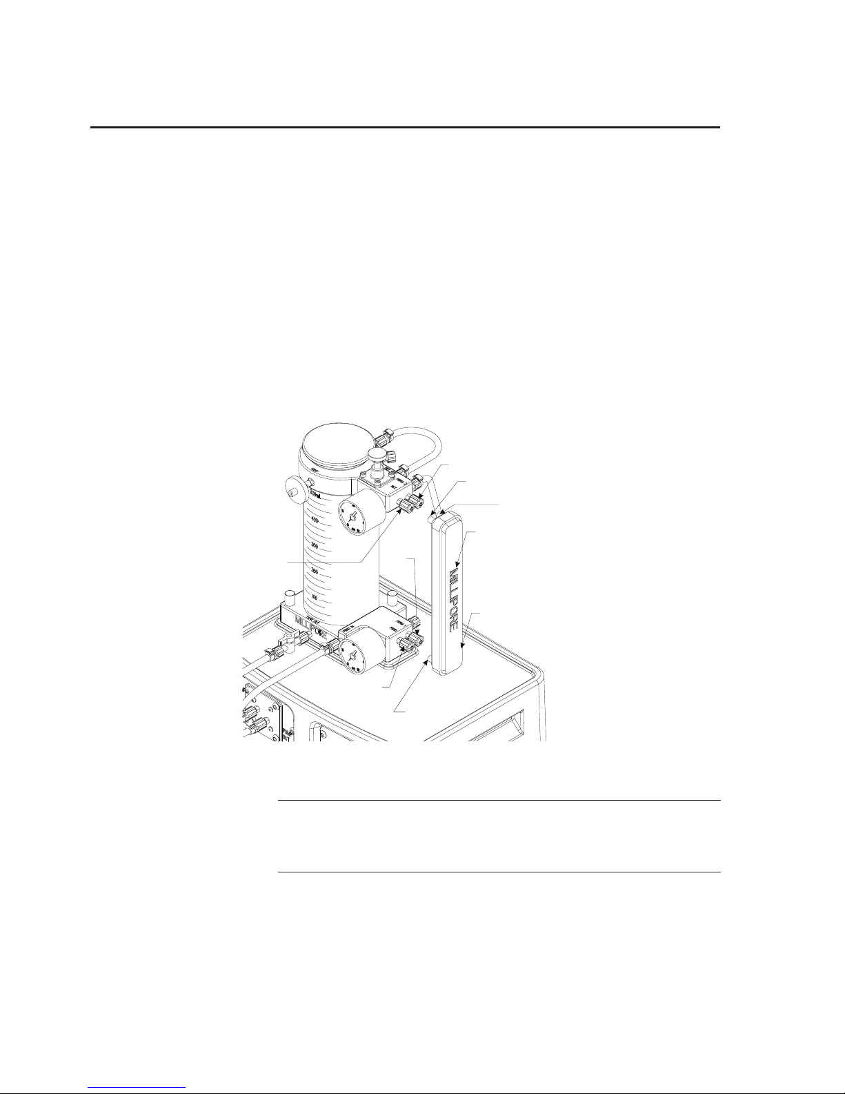
1. Remove plug from FEED, RET, PERM 1, and PERM 2 ports.
2. Align Pellicon XL device ports with Labscale 500 mL
Reservoir ports being sure that PERM and RET DEVICE
ports of device and reservoir match. Press device firmLy onto
reservoir ports. Turn the lock nuts until snug.
RESERVOIR
FEED PORT
RESERVOIR
PERM 1
PORT
RESERVOIR
PERM 2 PO RT
RESERVOIR
RET PORT
DEVICE
FEED PORT
DEVICE
PERM 1 PO RT
PELLICON XL DEVICE
DEVICE
PERM 2 PO RT
DEVICE
RET PORT
Figure 29: Install Pellicon XL Device
Note: Be sure pump tubing is installed before proceeding
and Sta-Pure (white) tubing is installed between pump
outlet and feed in port (FEED IN).
Page 31
Labscale Tangential Flow Filtration System User Guide 31
Flushing
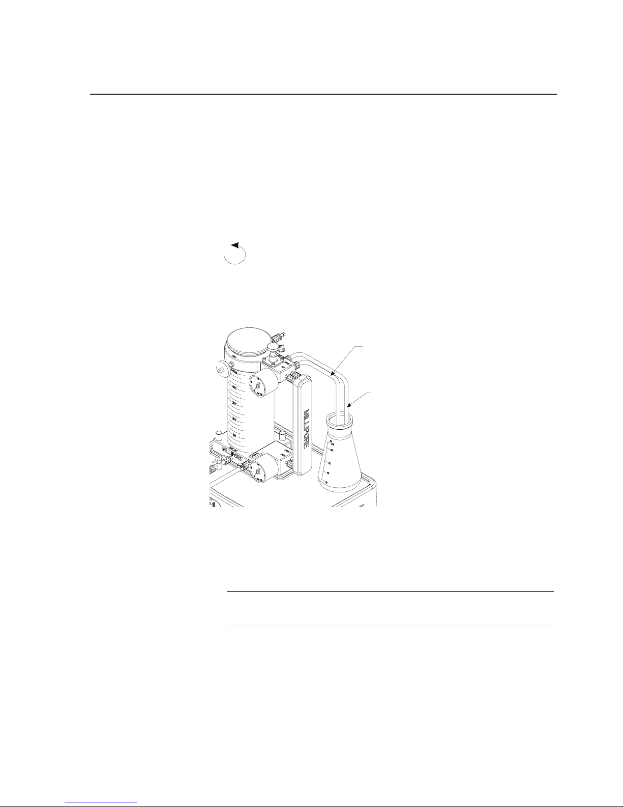
1. Disconnect retentate silicone (translucent) tubing from RET
IN port and place end of retentate tubing in waste collection
vessel.
2. Place end of permeate silicone (translucent) tubing into waste
collection vessel. Open retentate valve—turn counterclockwise
.
3. Remove reservoir cover and fill reservoir with 500 mL of
purified water. Remove plug from VENT port and open tank
outlet valve.
PERMEATE TUBING
RETENTATE TUBING
RESERVOIR
FEED PORT
RESERVOIR
PERM 1
PORT
RESERVOIR
PERM 2 PO RT
RESERVOIR
RET PORT
DEVICE
FEED PORT
DEVICE
PERM 1 PO RT
PELLICON XL DEVICE
DEVICE
PERM 2 PO RT
DEVICE
RET PORT
Figure 30: Flushing the Pellicon XL Device, steps 1–6.
4. Turn pump on - increase pump speed until feed pressure
gauge reads 1.38 Bar (20 psi).
Note: Check system connections for leaks—tighten connec-
tions if required
5. Continue pumping to the waste collection vessel until level in
the reservoir drops to 350 mL. Turn pump off.
Page 32
32 www.millipore.com
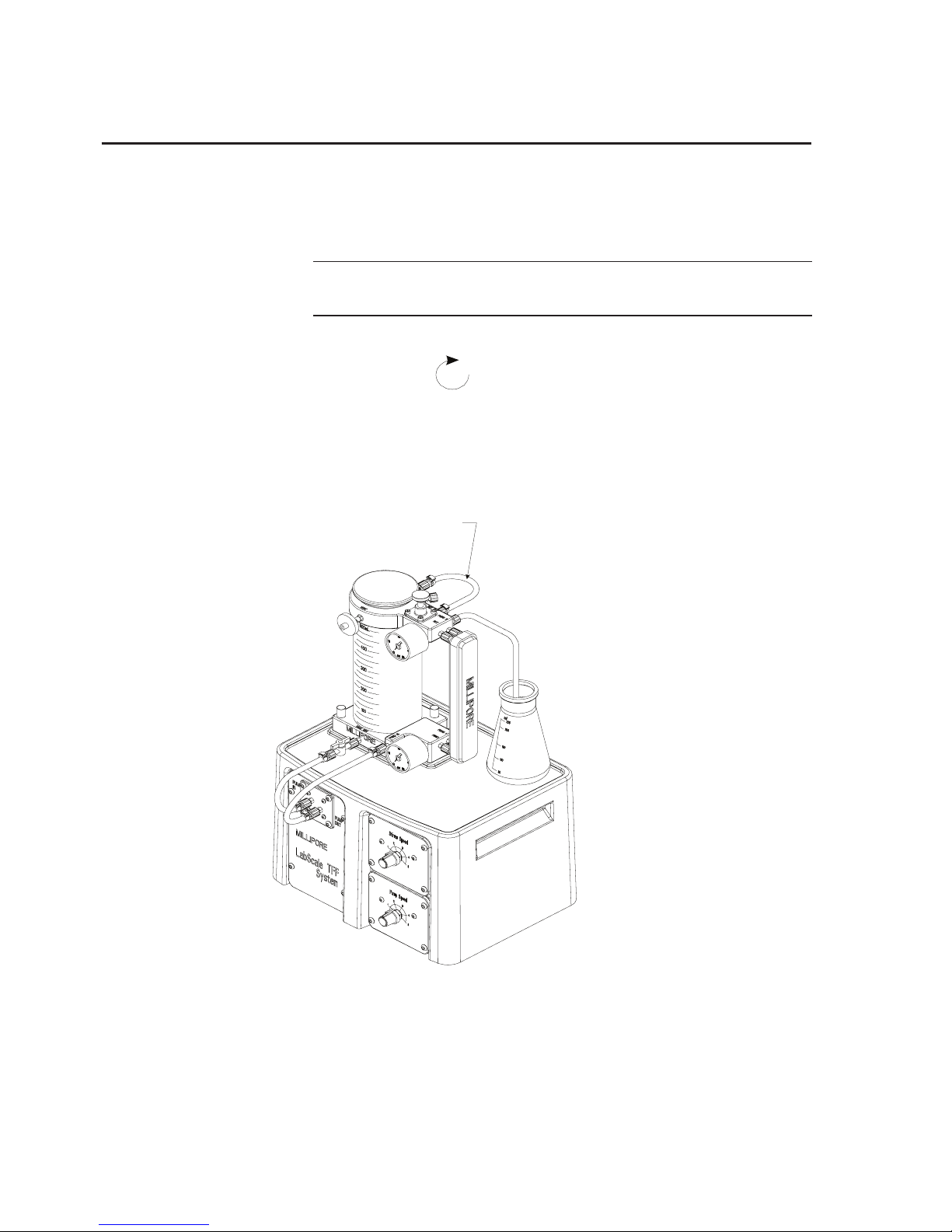
6. Reconnect the retentate silicone (translucent) tubing to the
RET IN port and turn pump on - increase pump speed until
feed pressure gauge reads 1.38 Bar (20 psi).
Note: Check system connections for leaks—tighten connec-
tions if required
7. Adjust retentate valve restriction by slowly turning retentate
valve clockwise
until the retentate pressure gage reads
0.69 Bar (10 psi).
8. Adjust pump speed and retentate valve restriction to achieve
2.07 Bar (30 psi) feed pressure and 0.69 Bar (10 psi) retentate
pressure.
RETENTATE TUBING
Figure 31: Flushing System Setup.
9. Continue flushing until the level in the reservoir drops to 50
mL. Turn pump off.
Page 33
Labscale Tangential Flow Filtration System User Guide 33
Drain System
See “Drain System” section, page 27.
Integrity Testing—Pellicon XL Device on System
Integrity Test Set Up
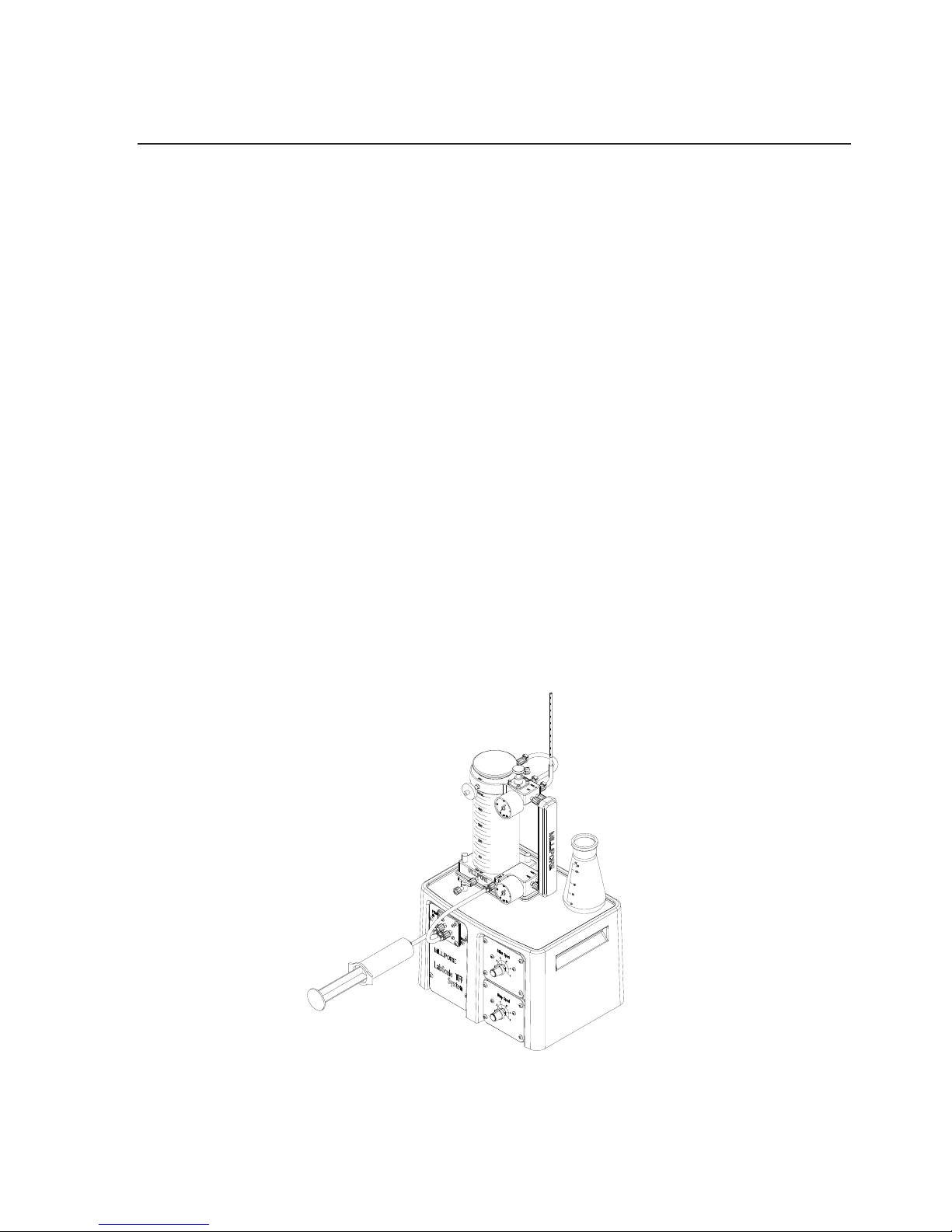
1. Close tank outlet valve and disconnect pump inlet tubing
(silicone, translucent) from the tank outlet valve. Close the
retentate valve.
Integrity Test Procedure
1. Obtain air integrity test pressure and airflow specifications
from the Certificate of Quality supplied with the device.
2. Insert syringe in the female luer end of the pump inlet tubing.
(silicone, translucent). Inject air into the tubing until the feed
pressure gauge reading reaches the recommended air integrity
test pressure.
Figure 32: Integrity Test Setup
Page 34

34 www.millipore.com
3. Add 0.1 mL of water to a 1 mL pipette. Insert bottom
of pipette into the end of the permeate tubing (silicone,
translucent).
4. Measure airflow by measuring the displacement of water in
the pipette for 30 seconds. Multiply the displaced volume by 2
to calculate the airflow (mL/min) and record.
5. Remove the pipette from the permeate tubing (silicone,
translucent). Open the retentate valve slowly to release the air
pressure in the system.
6. Reconnect the pump inlet tubing (silicone, translucent) to the
tank outlet valve.
The Pellicon XL device is integral if the measured airflow is
lessthan or equal to the airflow specification on the Certificate of
Quality.
Preconditioning
1. Place end of permeate tubing silicone (translucent) in waste
collection vessel.
2. Remove reservoir cover and fill reservoir with 50 mL of an
appropriate buffer. Remove plug from VENT port.
3. Open tank outlet valve. Turn pump on - increase pump speed
until feed pressure gauge reads 1.38 Bar (20 psi).
Note: Check system connections for leaks—tighten connec-
tions if required
4. Continue pumping to the waste collection vessel until the level
in the reservoir drops to the bottom of the reservoir stir bar
well.(Stop pump before air is pumped into the system.). Turn
pump off.
Page 35
Labscale Tangential Flow Filtration System User Guide 35
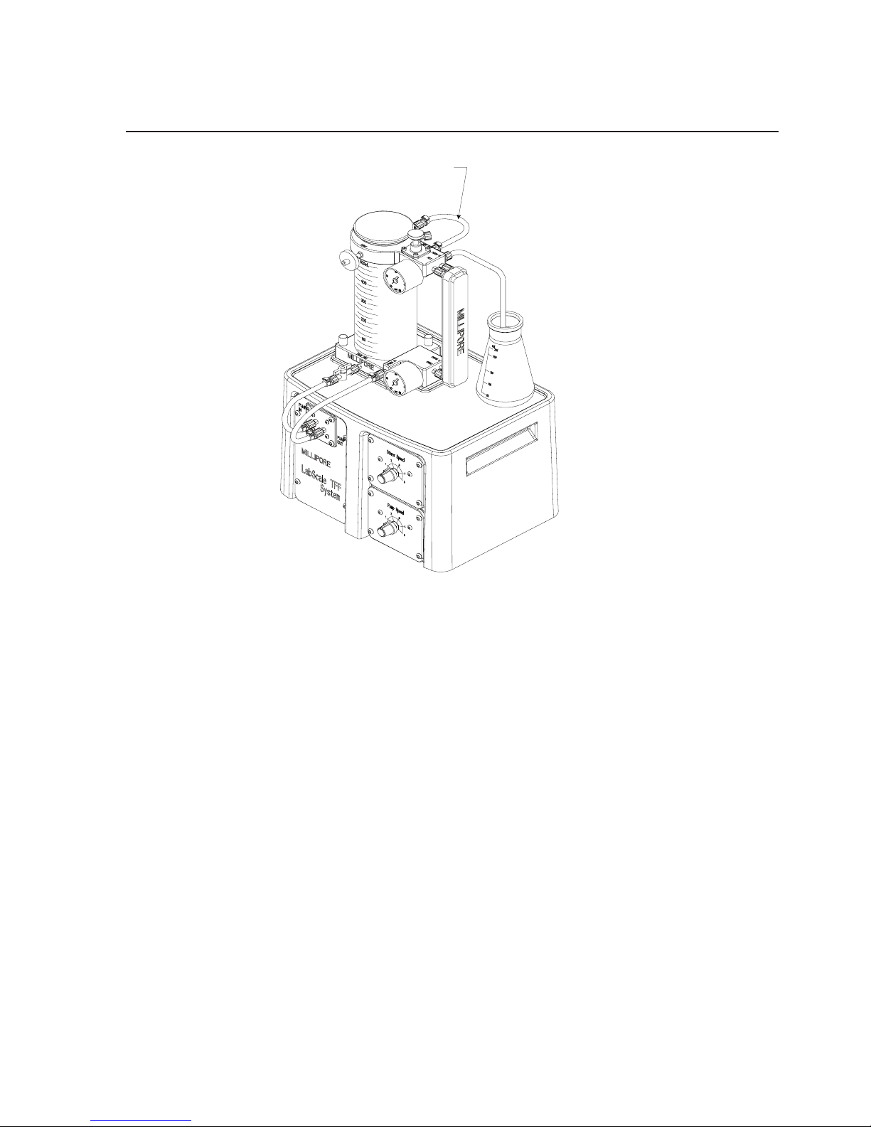
RETENTATE TUBING
Figure 33: Preconditioning Setup.
Drain Permeate Tubing
1. Disconnect the permeate tubing (silicone, translucent) from
the permeate outlet (PERM 2) port. Drain permeate tubing
into the waste collection vessel.
2. Reconnect the permeate tubing to the PERM 2 port.
Concentration
1. Remove reservoir cover and fill reservoir with sample to be
concentrated.
2. Ensure vent port is open by removing plug from VENT port
and leaving open or install a Millex Filter. Open tank outlet
valve.
Page 36
36 www.millipore.com
3. Turn pump on—increase pump speed until feed pressure
gauge reads 1.38 Bar (20 psi).
Note: Check system connections for leaks—tighten connec-
tions if required
4. Adjust retentate valve restriction by slowly turning retentate
valve clockwise
until the retentate pressure gauge reads
0.69 Bar (10 psi).
5. Adjust pump speed and retentate valve restriction to achieve
desired feed retentate pressures (recommend 2.07 Bar (30 psi)
feed / 0.69 Bar (10 psi) retentate).
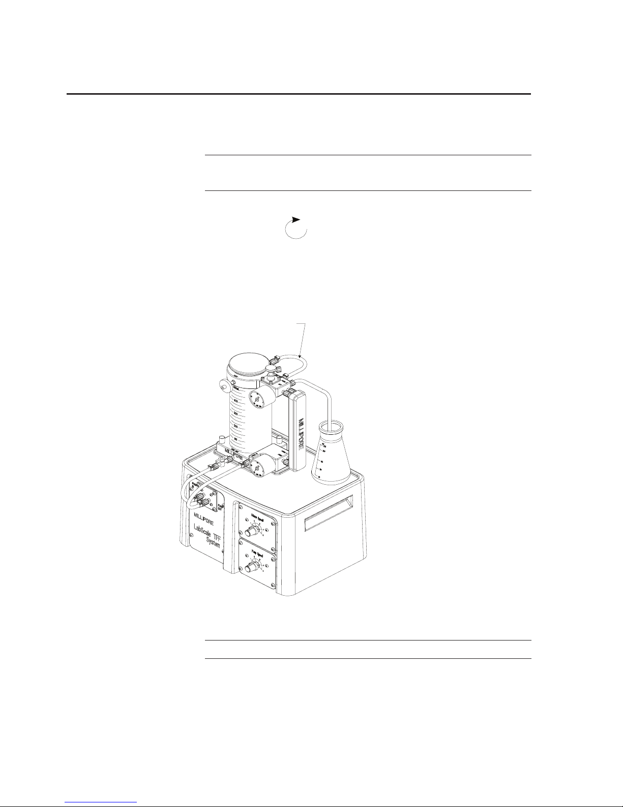
RETENTATE TUBING
Figure 34: Concentration Setup.
Note: Do not exceed 4.14 Bar (60 psi) feed pressure.
6. Continue processing until the desired concentration or volume
is reached. Turn pump off.
Page 37
Labscale Tangential Flow Filtration System User Guide 37
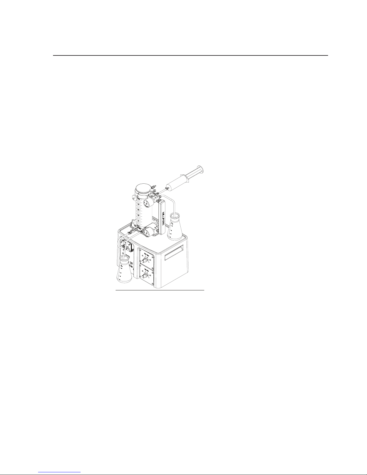
Product Recovery
1. Disconnect pump outlet tubing (Sta-Pure, white) from pump
outlet port and place in product recovery collection vessel.
2. Disconnect retentate tubing (silicone, translucent) from
retentate in port. Fluid should now drain by gravity. If
additional drainage is required, a syringe can be placed on the
end of the retentate tube and fluid can be blown down
RETENTATE TUBING
Figure 35: Product Recovery Setup.
3. Replace retentate tubing (silicone, translucent) in retentate
port. Reconnect pump outlet tubing (Sta-Pure, white).
4. Disconnect FEED IN tubing and place in collection vessel.
Open tank outlet valve, turn pump speed up to drain reservoir.
5. Reconnect the pump outlet tubing (Sta-Pure, white) to the
FEED IN port.
Page 38
38 www.millipore.com
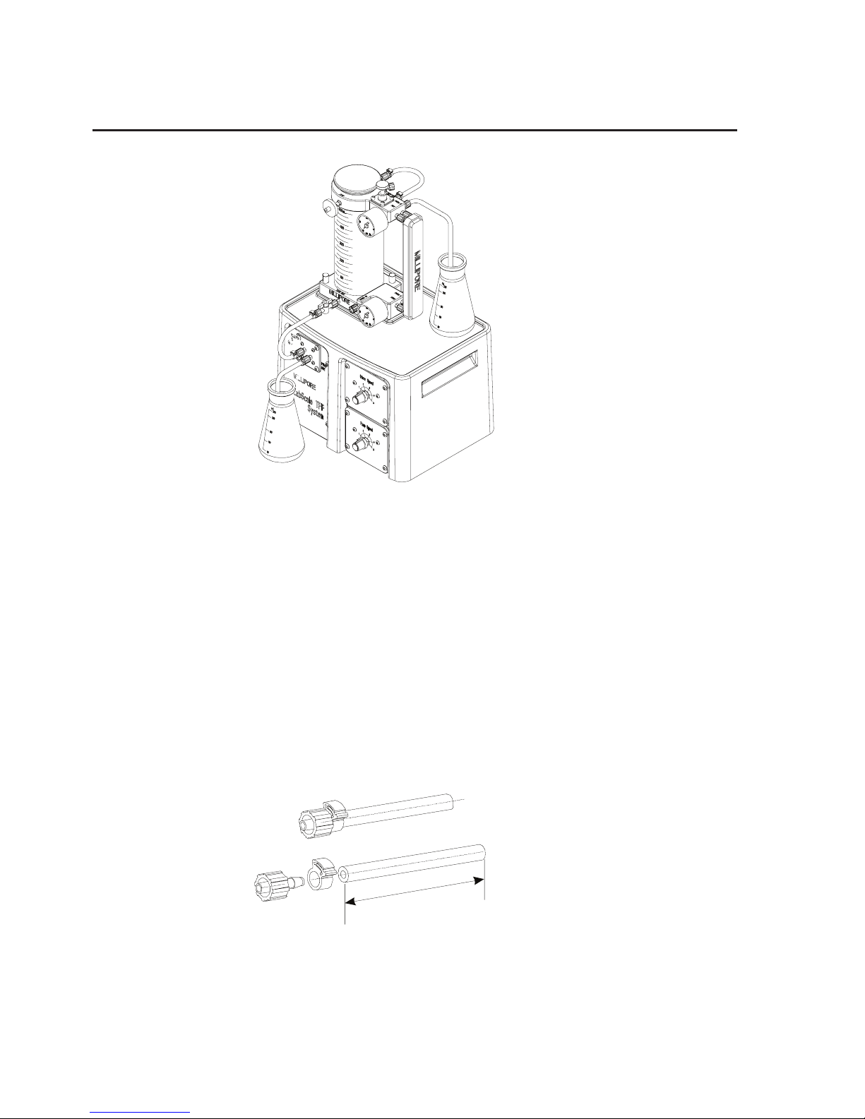
Figure 36: Product Recovery Setup.
Diafiltration—Vacuum
InstallDialtrationTubing
1. Cut silicone (translucent) tubing and insert a male luer x 1/8.
barb port in one end of the tubing as shown here. MALE
Place the other end of the diafiltration tubing in a vessel of
appropriate buffer.
L = 50 cm (20 inches)
Fittings: 1 male
L
Page 39
Labscale Tangential Flow Filtration System User Guide 39
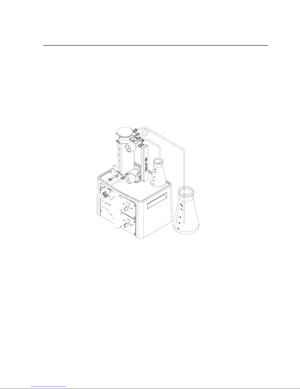
2. Connect male luer end of diafiltration tubing to the
diafiltration (DIA/RECIRC) port. Plug VENT port.
3. Insure that the end of the tubing remains below the buffer
level at all times.
As you remove permeate, a vacuum is created in the reservoir
which will siphon diafiltrate into the reservoir to maintain constant
volume.
L = 50 cm (20 inches)
Fittings: 1 male
L
Figure 37: Dialtration
Page 40

40 www.millipore.com
Shutdown
Cleaning Device
Recommended Cleaning Solutions
Note: Follow solution manufacturer’s directions for proper
handling. Please refer to the Pellicon XL Device
instructions packed with the device for the most
current cleaning solution information.
Cleaning
Agent
Concen-
tration
CatalogNos.withprex
PXBBiomax
®
(polyether-sulphone)
CatalogNos.withprex
PXC PL
(regenerated cellulose)
Temp
ºC
pH
Time
(min)
NaOH 0.1-
0.5N
X 40-45 13-13.7 30-60
NaOH 0.1N X 25-40 13 30-60
NaOC1 250
ppm
X 40-45 10-11 30-60
Note: Do not exceed 2.07 Bar (30 psi) feed pressure during
cleaning cycle.
Page 41

Labscale Tangential Flow Filtration System User Guide 41
Clean System
1. Disconnect retentate tubing (silicone, translucent) from RET
IN port and place in waste collection vessel. Place end of
permeate tubing in waste collection vessel.
2. Open retentate valve turn counterclockwise .
3. Remove reservoir cover and fill reservoir with 500 mL of
cleaning solution. Ensure vent port is open by removing plug
from VENT port and either leaving open or installing a
Millex Filter.
4. Open tank outlet valve.
5. Turn pump on - increase pump speed until feed pressure
gauge reads 1.38 Bar (20 psi).
Note: Check system connections for leaks—tighten connec-
tions if required
6. Continue pumping to the waste collection vessel until the level
in the reservoir drops to 250 mL.Turn pump off.Reconnect
the retentate (silicone, translucent) tubing to the RET IN port.
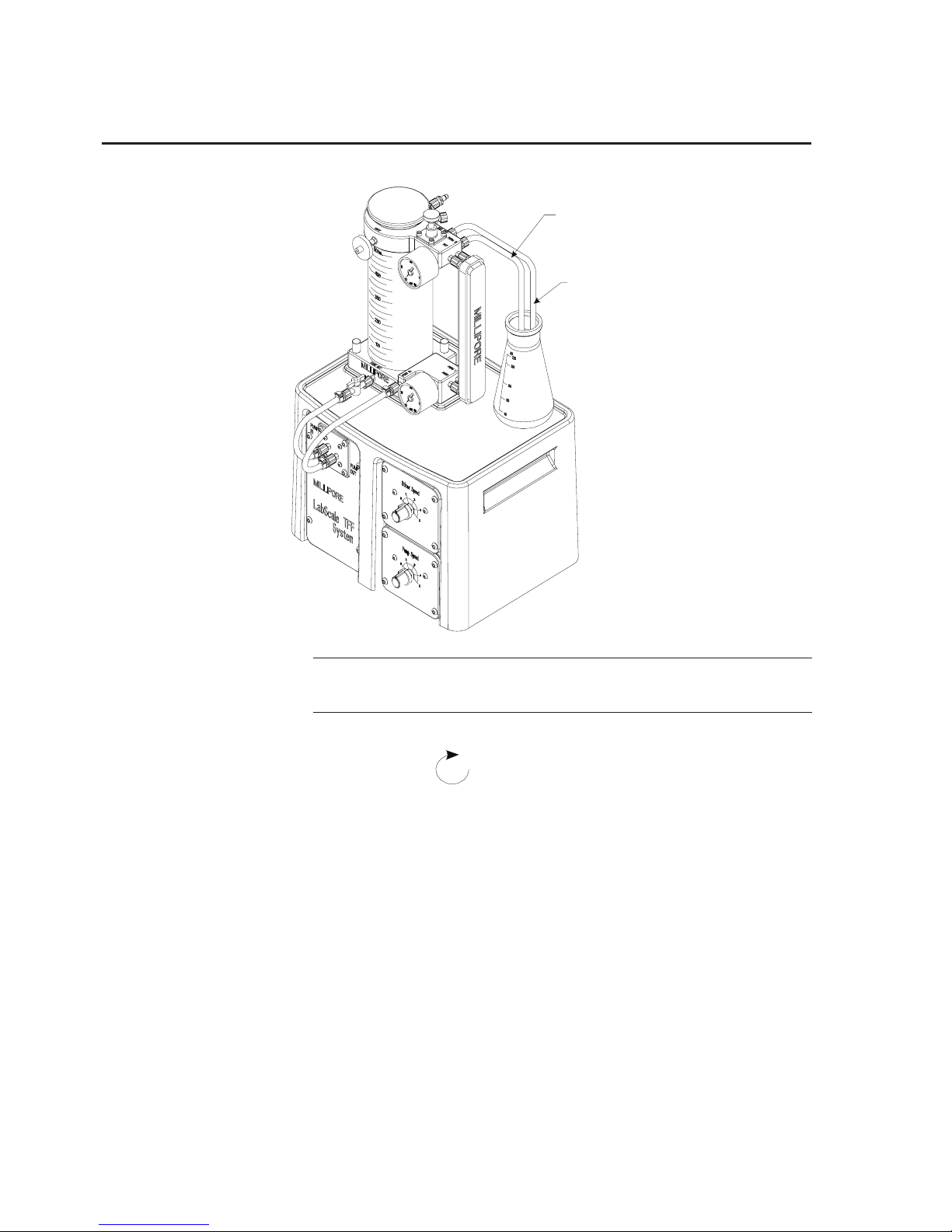
7. Connect the male luer end of the permeate tubing to the
recirculation (DIA/RECIRC) port. Turn pump on increase
pump speed until feed pressure gauge reads 1.38 Bar (20 psi).
Page 42
42 www.millipore.com
PERMEATE TUBING
RETENTATE TUBING
Note: Check system connections for leaks—tighten connec-
tions if required
8. Adjust retentate valve restriction by slowly turning retentate
valve clockwise
until the retentate pressure gage reads
0.69 Bar (10 psi). Adjust pump speed and retentate valve
restriction to achieve 2.07 Bar (30 psi) feed pressure and 0.69
Bar (10 psi) retentate pressure.
9. Recirculate the cleaning solution for 30 - 60 minutes. Turn
pump off.
Page 43

Labscale Tangential Flow Filtration System User Guide 43
Drain System
See “Drain System” section, page 27.
Flushing Device
Repeat flushing procedure detailed in “Flushing” section, page 31.
See instructions enclosed with the Pellicon XL device for storage
information.
Clean Base
1. Disconnect power.
2. Exterior surfaces of the Labscale 500 mL Reservoir and the
Labscale System Base may be cleaned with a mild soap and
water solution.
Page 44

44 www.millipore.com
Specications
Specifications
All wetted parts meet the requirements of USP Class VI testing
and CFR 21 regulations.
Dimensions
21.6 x 27.9 cm (8.5 x 11 inches)
Height: 45.7 cm (18 inches)
Weight 5.9 kg (13 lb)
Maximum pump outlet pres-
sure
5.86 Bar (85 psig)
Maximum gauge pressure: do not exceed gauge scale
Maximum Pellicon XL Device
operating pressure
see instructions
supplied with device
Operating temperature range 4.45°CFeedowrate:10.100
mL/min at 4.14 Bar (60 psi)
Minimum recirculation vol-
ume:
20 mL
Power 115V, 60 Hz or 230V, 50 Hz
CE mark
Page 45
Labscale Tangential Flow Filtration System User Guide 45
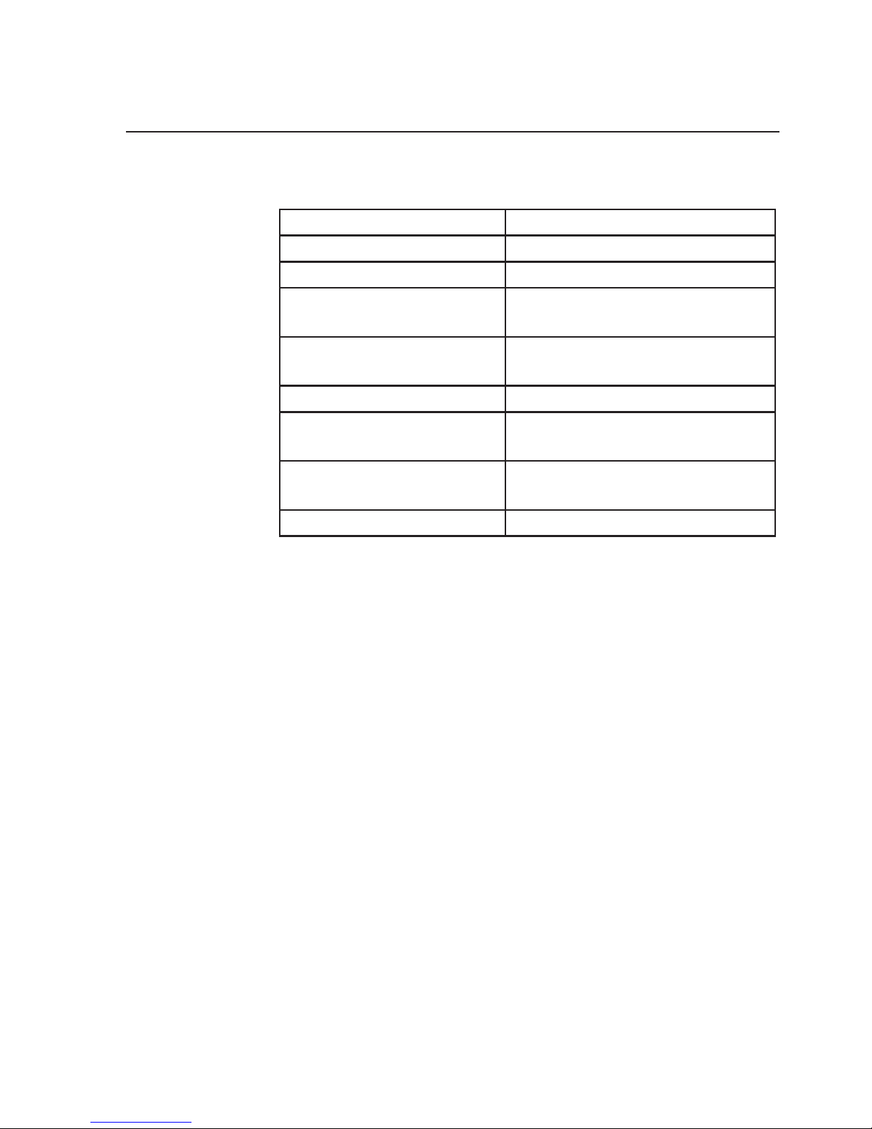
Materials of Construction
500 mL reservoir acrylic
Reservoir cover polypropylene
Reservoir cover gasket EPDM
Luerttings 316 stainless steel
and polypropylene
Tubing Platinum-cured silicone (translu-
cent) and Sta-Pure (white) tubing
Diaphragm pump housing glass-lledpolypropylene
Diaphragm pump dia-
phragm
PTFE coated
Diaphragm pump check
valve
polypropylene and Simriz® elas-
tomer
Housing/enclosure polyurethane
Page 46

46 www.millipore.com
EC Compliance Certificate
Certificate of Compliance
Millipore Corporation certifies that the part listed hereafter :
Product name : LABSCALE
Catalogue # :
XX42LSS12
XX42LSS13
,
• Are manufactured (or supplied) by a Millipore facility whose Quality Management System is
approved by an accredited registering body to the appropriate ISO 9001 Quality Systems Standard.
• Are manufactured in accordance with applicable Millipore Standard Procedures.
• Are tested in accordance with applicable Millipore Quality Specifications.
CE Compliance : Declaration of Conformity
We certify that this system is designed and manufactured in application of the following European Council directives :
• 73/23/CEE relating to Electrical equipment designed for used in certain voltage limits
• 89/336/CEE relating to Electromagnetic compatibility (EMC)
Standards to which conformity is declared applicable are the following :
EMC emissions
• EN61000-3-2 : Harmonic currents
• EN61000-3-3 : Voltage fluctuations and flicker
• EN 55011 : Conducted disturbances on power ports
• EN 55011 : Radiated disturbances electric component
EMC Immunity
• EN 61000-4-2 : Electrostatic discharges immunity test
• EN 61000-4-3 : Radiated , radio-frequency, electromagnetic field immunity test
• EN 61000-4-4 : Electrical fast transient burst immunity test
• EN 61000-4-5 : Surge immunity test
• EN 61000-4-6 : Conducted disturbances, induced by radio-frequency fields, immunity test
• EN 6100-4-11 : Shot interruptions and voltage variations immunity test
Electrical safety
• IEC 61010-1:2001 : Safety requirements for electrical equipment for measurement, control and laboratory use -
Part 1: General requirements
Guy Reymann
Quality Manager
Millipore, Hardware Systems Operations
Molsheim, France
®
Page 47
Labscale Tangential Flow Filtration System User Guide 47
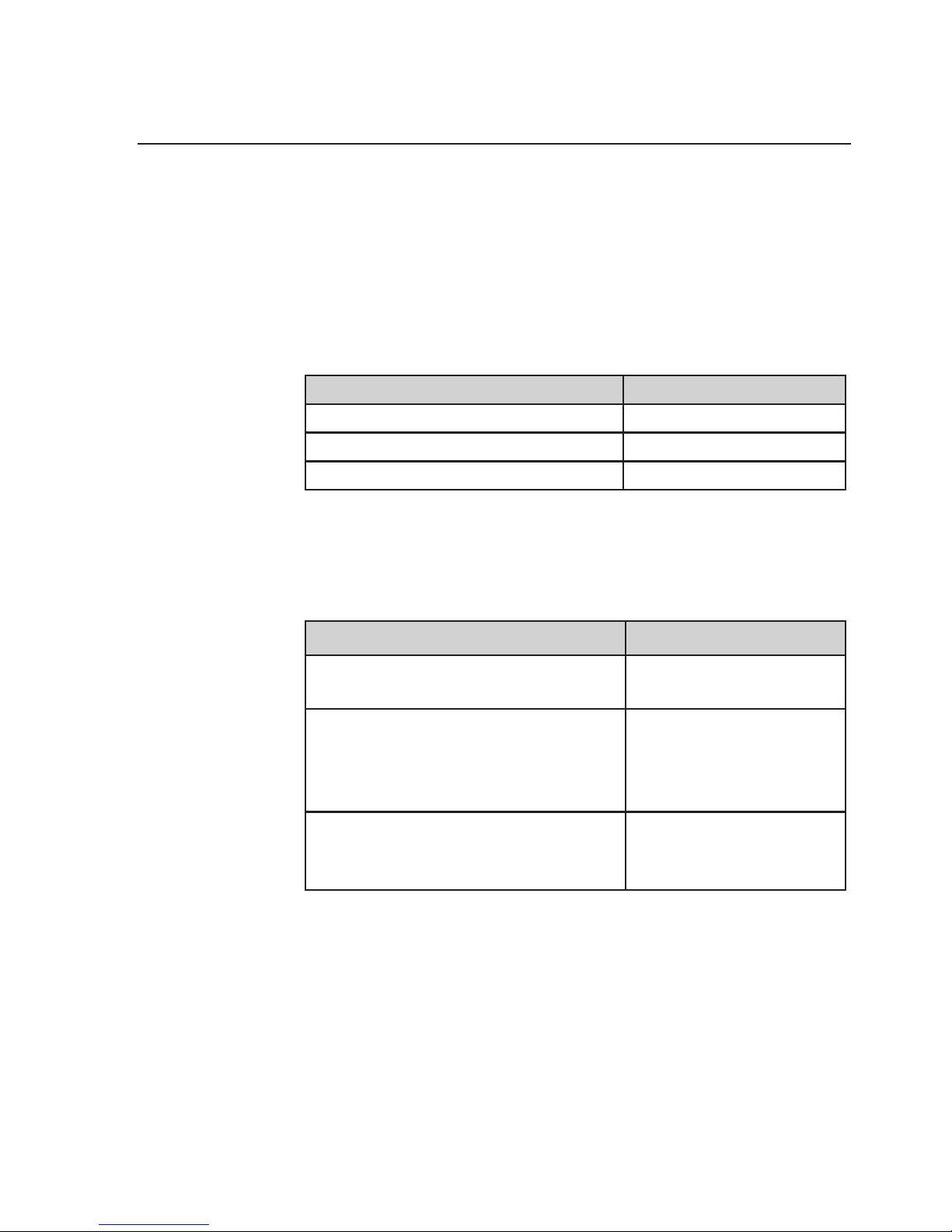
Labscale TFF System
Ordering Information
Labscale TFF system kit
Description Catalog Number
115V XX42LSS11
230V XX42LSS12
230V (GB) XX42LSS13
Includes: Labscale 500 mL Reservoir, Labscale Stir Base with
Labscale Pump Module installed.
Labscale TFF system components are also available
separately.
Description Catalog Number
Labscale 500 mL Reservoir
with gauges
XX42RES01
Labscale Stir Base
115V
230V
230V(GB)
XX42STR11
XX42STR12
XX42STR13
Labscale Pump Module
(can only be used with Millipore
Labscale Stir Base)
XX42PMP01
Page 48
48 www.millipore.com
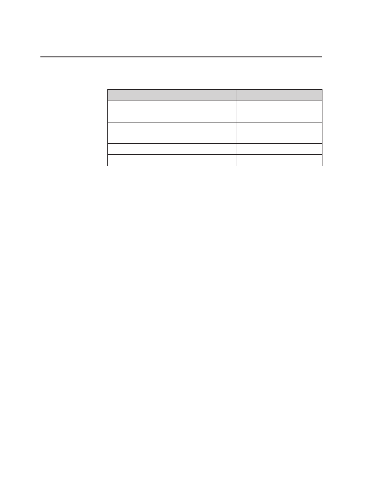
Compatible pumps and pump head
Description Catalog Number
Peristaltic pump drive, 115V, variable
speed, 60.600 rpm
XX8200115
Peristaltic pump drive, 230V, variable
speed, 60.600 rpm
XX8200230
Pump head, 480 mL/min (3 roller) XX8000003
Labscale system 1/8 in. tubing kit XX80LFL25
After prolonged storage, the tubing may absorb a small volume
of water. As a result, the tubing color may change from translucent to opaque, which is normal. Air or oven drying will return
the color to translucent.
Pellicon XL Devices
Please see instructions supplied with the Pellicon XL Device for
ordering information.
Page 49
Labscale Tangential Flow Filtration System User Guide 49
Labscale TFF System
Maintenance
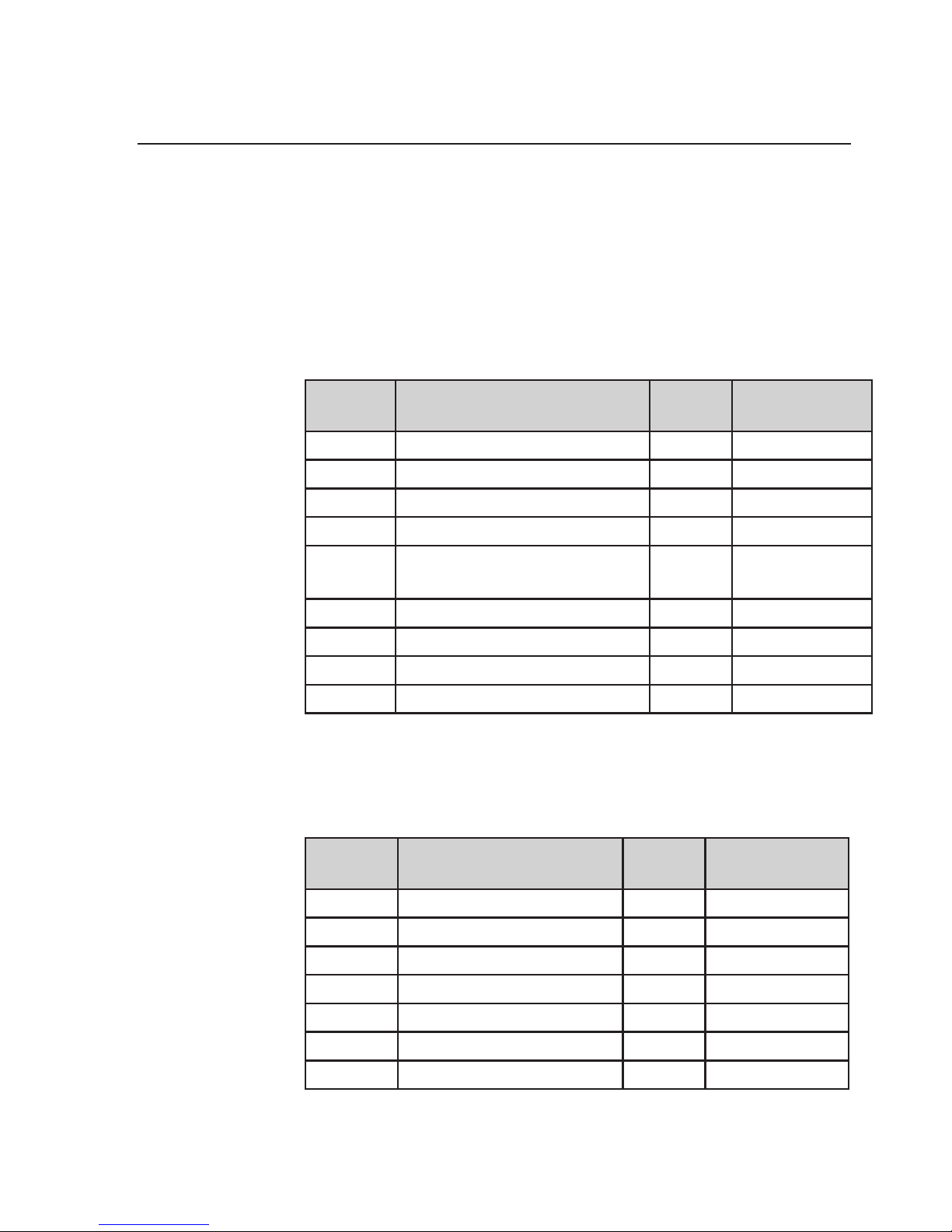
Labscale Stir Base Spare Parts
Item
Number
Description
Qty per
Cat #
Catalog
Number
1 Fuse 10 XX42LSP40
2 Thumb Screw 10 XX42LSP41
3 Transformer – 115V 1 XX42LSP42
4 Transfromer – 230V 1 XX42LSP43
5 Transformer – 230V (Great
Britain)
1 XX42LSP44
6 Motor, Stirrer 1 XX42LSP45
7 Pump Assembly, Diaphragm 1 XX42LSP46
8 Speed Controller, Stirrer 1 XX42LSP47
9 Speed Controller, Pump 1 XX42LSP48
Labscale 500 mL Reservoir Spare Parts
Item
Number
Description
Qty per
Cat. #
Catalog
Number
1 Pressure gauge 1 XX42LSP20
2 Stir Bar 5 XX42LSP21
3 Tank Outlet Valve 12 XX42LSP22
4 Valve Diapragm 1 XX42LSP23
5 Cover, Tank 1 XX42LSP24
6 O-Ring, Tank cover 5 XX42LSP25
7 Filter, Vent 50 SLFG025LS
Page 50

50 www.millipore.com
Item
Number
Description
Qty per
Cat. #
Catalog
Number
8 Fitting, Luer-LokTM
Female x 10-32 St. St’l
10 XX42LSP26
9 Fitting, Luer-Lok Male x
10-32 St. St’l
10 XX42LSP27
10
10-1
10-2
Tubing:
Platinum-cured
Sta-Pure Tubing
XX80LFL256 ft
2 ft
11
11-1
11-2
11-3
11-4
11-5
11-6
Plastic Fitting Kit:
Fitting, Female
Fitting, Male Luer-Lok
Plug
Fitting, Luer-Lok Ring
Fitting, Male Luer-Lok
x 1/8 in. Barb
Fitting, Female LuerLok x 1/8 in. Barb
Clamp, Ratchet
XX42LSP28
10
10
10
10
10
10
10
Page 51
Labscale Tangential Flow Filtration System User Guide 51
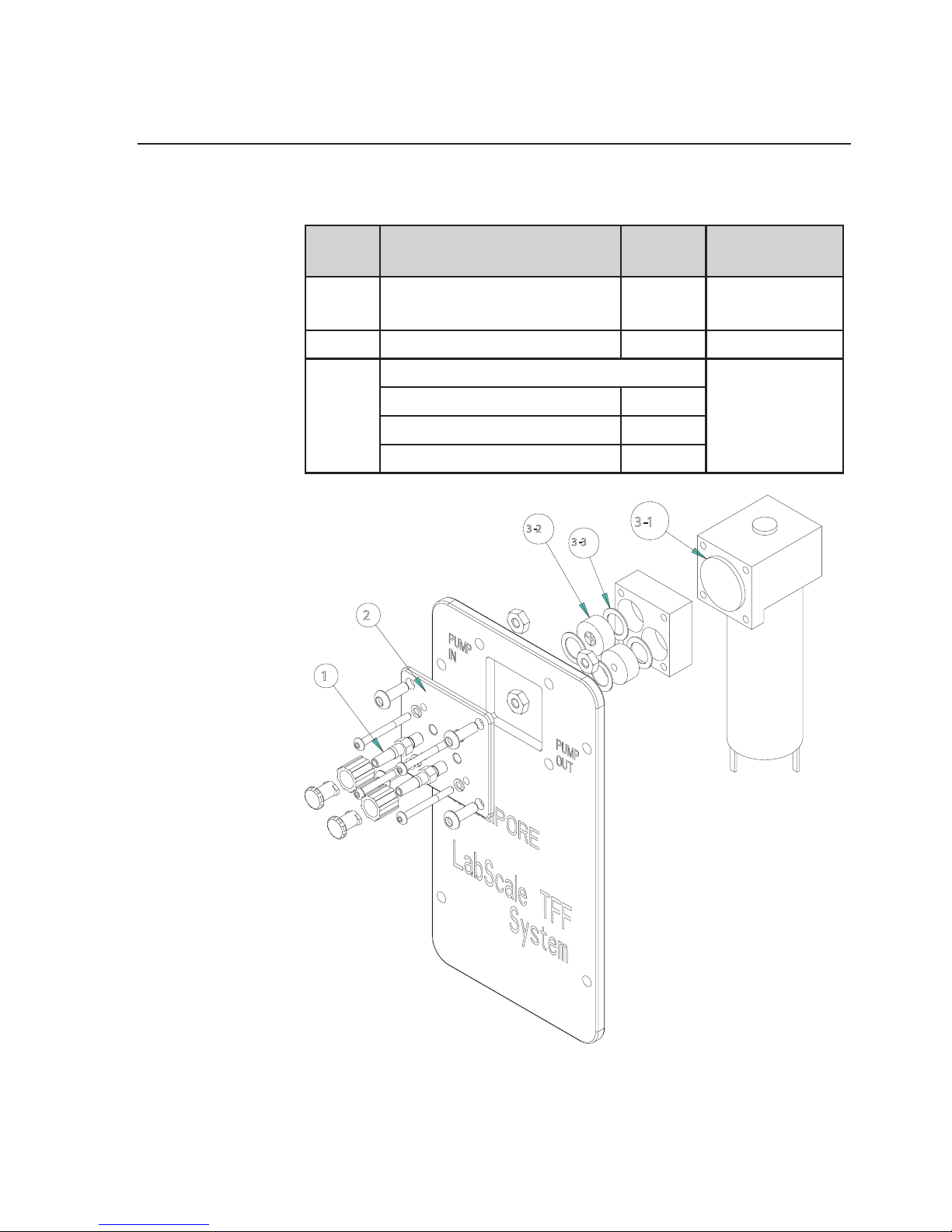
Labscale Pump Module Spare Parts
Item Description
Qty per
Cat #
Catalog
Number
1 Fitting, Male Luer-Lok x
10-32 St. St’l
10 XX42LSP27
2 Manifold, Pump 1 XX42LSP80
3
3-1
3-2
3-3
Pump Rebuild Kit Contains:
XX42LSP81
Diaphragm 1
Check Valve 2
Gasket, Check Valve 4
1
3-2
3-3
3-1
2
Page 52
52 www.millipore.com
PumpCheckValveFlushing
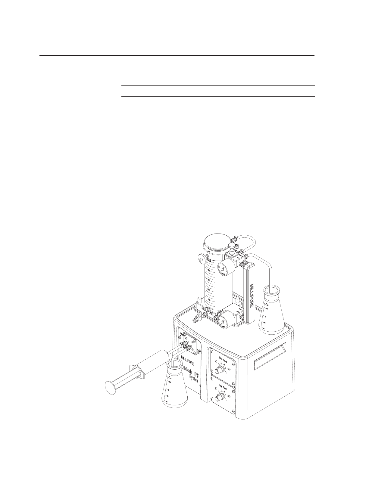
Note: The pump should be shut off during this procedure
1. Close the tank outlet valve
2. Disconnect the pump inlet tubing (silicone, translucent) from
the tank outlet valve.
3. Disconnect the pump outlet tubing (Sta-Pure, white) from
the reservoir FEED IN port and place the end in a waste
collection vessel
4. Fill a syringe with warm water and inject the water through
the pump and into the waste collection vessel.
5. Repeat Step 4 until approx. 100–200 mL of water flushed
through the check valves
Page 53

Labscale Tangential Flow Filtration System User Guide 53
Diaphragm Pump Maintenance
Pump Panel Disassembly
1. Disconnect the AC adapter from its power source
2. Disconnect the AC adapter from the enclosure
3. Remove the Pump Panel from the enclosure
4. Disconnect the wires from the pump
CheckValveReplacement
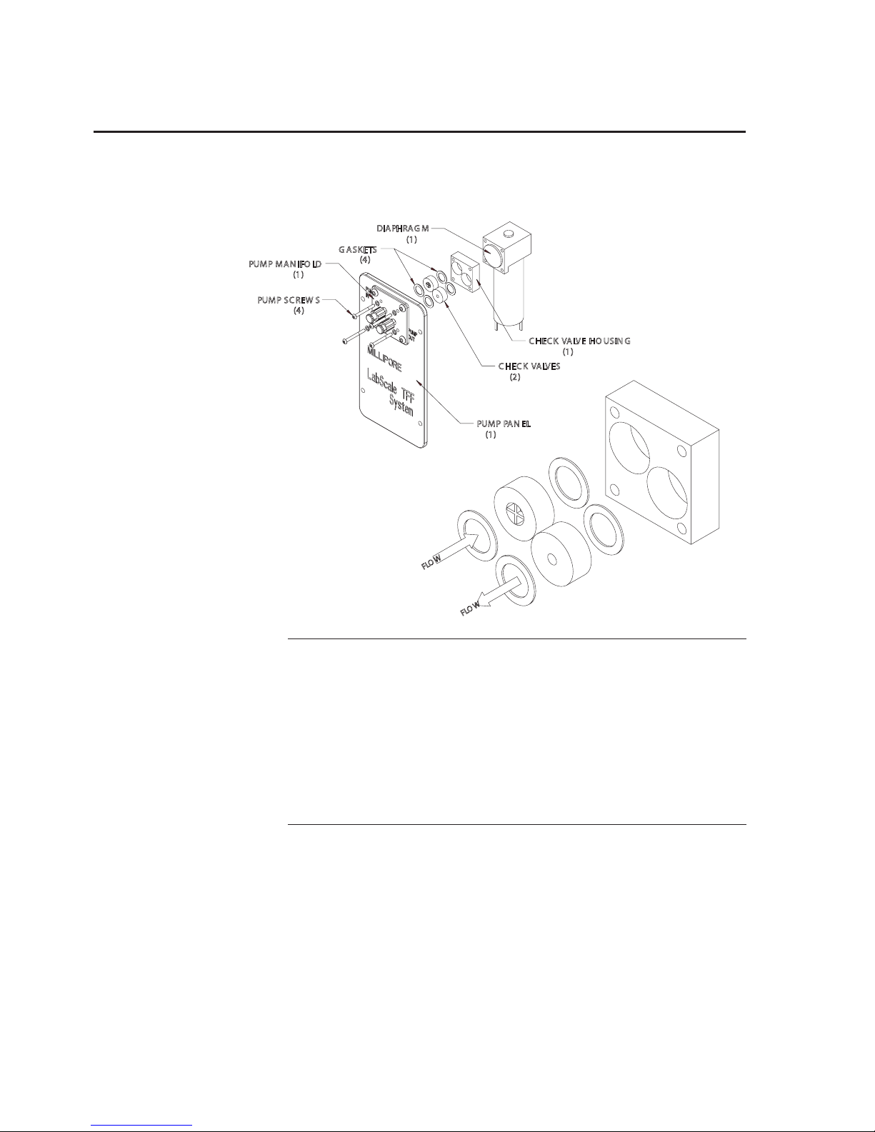
1. Remove the (4) Pump Screws
2. Disasemble the pump from the pump manifold
3. Remove the (2) check valves and (4) gaskets from the check
valve housing.
4. Install new check valves and gaskets as shown below
Diaphragm Replacement
1. Unscrew the diaphragm from the pump in a counterclockwise
direction.
2. Install the new diaphragm by screwing the diaphragm in a
clockwise direction until tight
Pump Reassembly
1. Seat the check valve housing onto the diaphragm
2. Seat the pump with check valve housing onto the pump
manifold
3. Install the (4) pump screws and tighten
Pump Panel Installation
1. Reconnect the pump wires
Page 54
54 www.millipore.com
2. Reinstall the pump panel on the enclosure
C HEC K VALVE HO US ING
(1)
PUMP PA N EL
(1)
PUMP MA NIFO LD
(1)
DIAPH RAG M
(1)
C HEC K VALVE S
(2)
G AS KETS
(4)
PUMP SC REW S
(4)
F
L
O
W
F
L
O
W
IMPORTANT:
Check Valve orientation is as shown. Improper orientation
of the check valves will damge the check valves and
cause the pump not to function. The check valves are
keyed to assist with proper orientation.
DO NOT FORCE CHECK VALVES INTO
HOUSING!
Page 55
Labscale Tangential Flow Filtration System User Guide 55
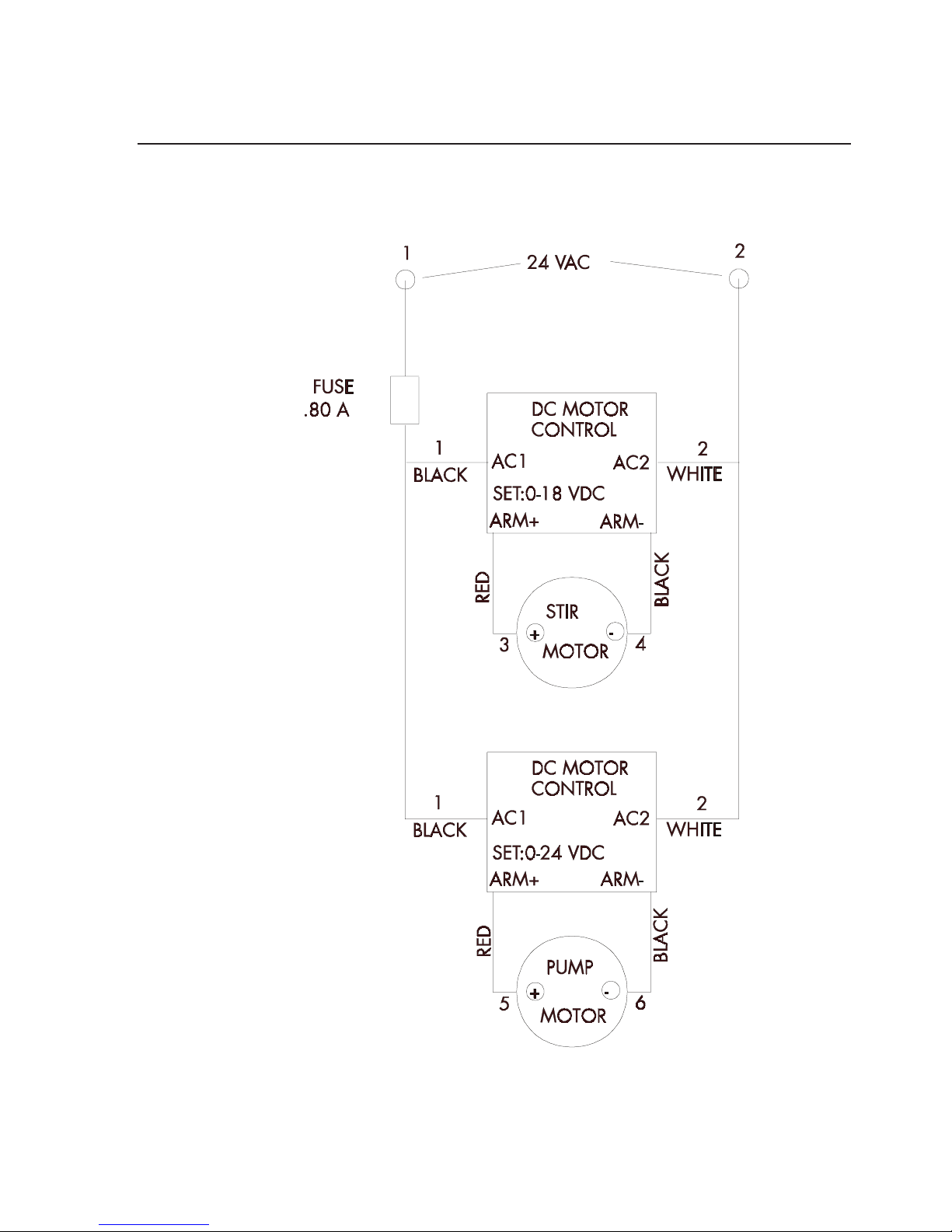
Electrical Schematic
Page 56

56 www.millipore.com
Labscale TFF System
Troubleshooting
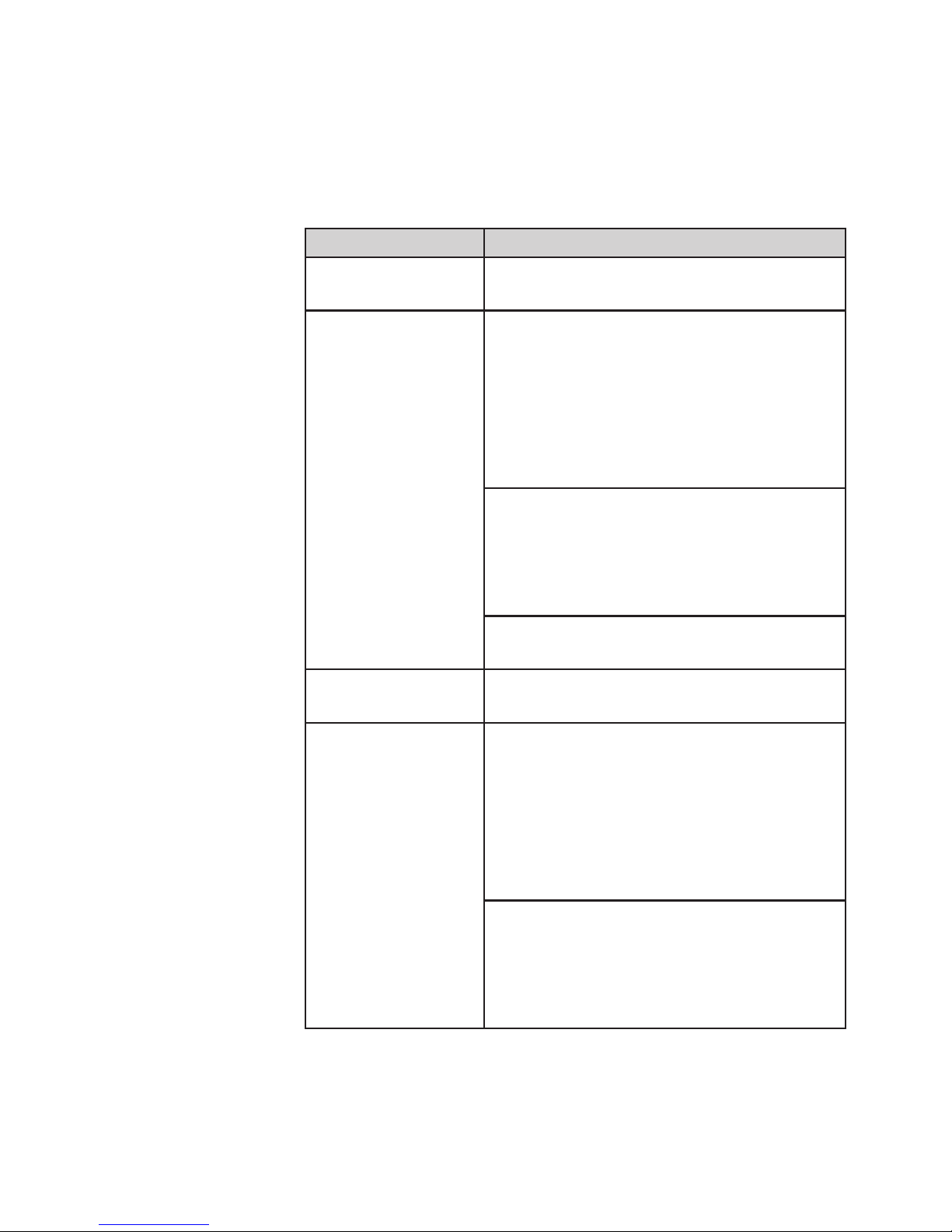
Electrical/Control
Symptom Solution
Pump and stirrer do
not operate
Check the following:
AC adapter plugged into live receptacle
with appropriate voltage
AC adapter plugged into receptacle on
the rear of system enclosure
Check fuse on the rear of the system
enclosure
Pump operates but
the stirrer does not
Haveaqualiedtechniciancheckthe
function of the stirrer speed controller
and the stirrer motor.
Stirrer operates but
the pump does not
Haveaqualiedtechniciancheckthe
function of the pump speed controller
and the pump motor.
Page 57
Performance
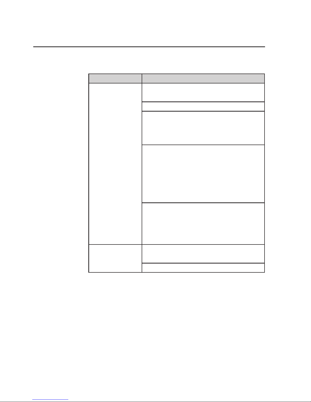
Symptom Solution
MixingStirrer speed
too slow
Haveaqualiedtechniciancheckthe
function of the stirrer speed controller.
FlowPumpow
too low
If theuidmovesbackandforthinthe
pump inlet or pump outlet tubing, particulates may be impairing the pump check
valves from closing. Ensure pump check
valvesareclean.Seecheckvalveushing
procedure in maintenance section “Pump
check Valve Flushing” of this manual.
If ushingthecheckvalvesdoesnoteliminate the problem, replace pump check
valves. See check valve replacement procedure in maintenance section “Diaphragm
Pump Maintenance” of this manual.
Haveaqualiedtechniciancheckthe
function of the pump speed controller.
No Flow (Pump
operating)
Ensure tank outlet valve is open.
Excessive pulsation Iftheuidmovesbackandforthinthe
pump inlet or pump outlet tubing, particulates may be impairing the pump check
valves from closing. Ensure pump check
valvesareclean.Seecheckvalveushing
procedure in maintenance section “Pump
check Valve Flushing” of this manual.
If ushingthecheckvalvesdoesnoteliminate the problem, replace pump check
valves. See check valve replacement procedure in maintenance section “Diaphragm
Pump Maintenance” of this manual.
Page 58
58 www.millipore.com
Pressure
Symptom Solution
System pressure
too low
Check the following:
Pressure gauge calibration.
Ensure tank outlet valve is open.
Ensure pump inlet and outlet tubing are
connected correctly. Ensure Sta-Pure
(white) tubing is connected from pump
outlet to feed in port (FEED IN).
If theuidmovesbackandforthinthe
pump inlet or pump outlet tubing, particulates may be impairing the pump check
valves from closing. Ensure pump check
valvesareclean.Seecheckvalveushing
procedure in maintenance section “Pump
check Valve Flushing” of this manual
If ushingthecheckvalvesdoesnot
eliminate the problem, replace pump check
valves. See check valve replacement procedure in maintenance section “Diaphragm
Pump Maintenance” of this manual
System Pressure
too high
Check the following:
Pressure gauge calibration
The retentate back-pressure valve is closed
Page 59

Labscale Tangential Flow Filtration System User Guide 59
Page 60

Technical Assistance
For more information, contact the Millipore office nearest you. In
the U.S., call 1-800-MILLIPORE (1-800-645-5476). Outside the
U.S., see your Millipore catalogue for the phone number of the
office nearest you or go to our web site at www.millipore.com/
offices for up-to-date worldwide contact information. You can also
visit the tech service page on our web site at http://www.millipore.
com/techservice.
Millipore,Pellicon,BiomaxandMillexareregisteredtrademarksofMilliporeCorporation.TheMlogoand
Labscale are trademarks of Millipore Corporation. Sta-Pure is a trademark of W. L. Gore & Associates.
Simriz is a trademark of Freudenberg & Company. Luer-Lok is a trademark of Becton, Dickinson and Company. ISO is a trademark of The International Organization for Standardization.
P73614 Rev B 04/2011 © 1997, 2009, 2011 Millipore Corporation. All rights reserved.
 Loading...