

Millimar C 1208, C 1240, C 1216 Operating Instructions Manual
Mahr GmbH, Standort Esslingen, Reutlinger Straße 48, 73728 Esslingen
Tel. +49711 9312-600, Fax +49 711 9312-756 mahr.es@mahr.de, www.mahr.de
Operating Instructions
3723047
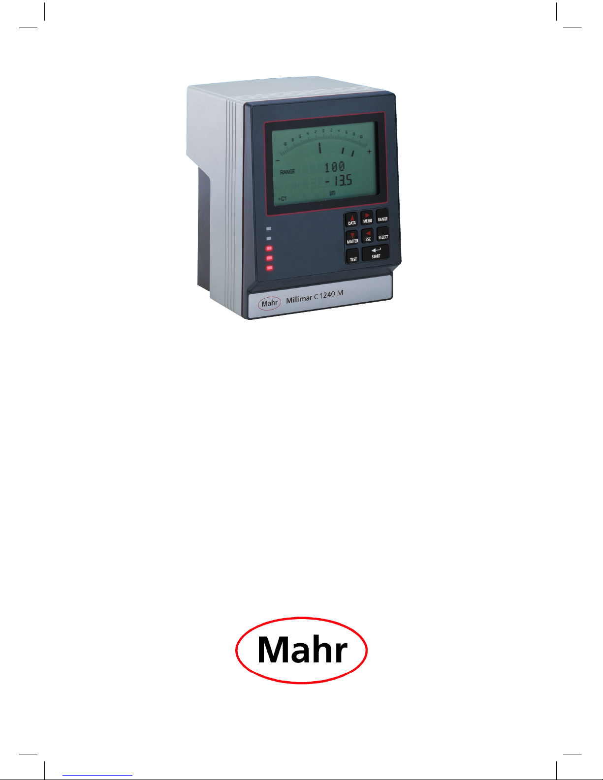
Millimar C 1208 /C 1216 / C 1240
08.11 .2016

1
Mahr GmbH, Millimar C1208/C1216/C1240
Dear valued customer,
Congratulations on choosing a product by Mahr
GmbH. We kindly request that you follow the
instructions below in order to ensure the longterm precision of your measuring instrument.
We operate a policy of continuous improvement and are constantly developing our products, especially with regard to renaming of type
designations. It is possible therefore that there
may be slight differences between the text and
illustrations in this document and the measuring
instrument in your possession. We reserve the
right to make changes to the design and scope
of supply, the right to undertake further technical
developments, and all rights relating to translation of this documentation.
© by Mahr GmbH, Standort Esslingen
Permitted Uses
The Millimar C 1208/C 1216/C 1240 is an electronic length measuring and evaluating instrument for use in a production environment.
Permitted use is subject to compliance with all
published information relating to this product.
Any other use is not in accordance with the permitted use. The manufacturer accepts no liability
for damages resulting from improper use. All
statutory and other regulations and guidelines
applicable to the area of use must be observed.
There are 3 different versions available:
C 1208/C 1216 M, T, F:
One or two inductive probes can be connected.
C 1208 PE:
a pneumatic sensor (air plug gage, air ring gage)
can be connected.
C 1240 M:
One or two Mahr compatible inductive
probes (including the probe type 1340,
which up to now could only be used
in conjunction with the evaluation unit
Millimar 1240) can be connected.
The operating, maintenance and repair information specified in these operating instructions and the operating instructions for
the measuring station components must
be observed.
These Operating Instructions contain the following symbols:
General information.
Important information. Non-observance of this information can result in incorrect measurements or even damage to the instruments!
2
Mahr GmbH, Millimar C1208/C1216/1240
Disposal
Electronic devices, including accessories and used batteries (rechargeable
and disposable), must not be disposed of as regular garbage, since they
contain high-value materials that can be recycled and reused. European
Directive 2012/19/EU (WEEE) requires that electrical and electronic devices
must be collected separately to unsorted municipal waste so that they
may be subsequently reprocessed. The crossed-out garbage can symbol
indicates that separate collection is necessary.
Mahr GmbH carries out the redemption and disposal of its electrical and
electronic products in accordance with legal requirements. Please contact
your local service representative.
Mahr GmbH
Standort Esslingen
Reutlinger Straße 48
73728 Esslingen
Mahr GmbH is registered in Germany with the Elektro-Altgeräte-Register
(EAR, 'national register for used electrical appliances') under WEEE Reg. No.
DE 56624193.
Voided warranty
Service that is due to viruses that were introduced via a network connection or other
data carrier, are generally excluded from the warranty services.
Storage temperatures below –10 °C or above +50 °C and relative humidity levels
above 85 % will invalidate the warranty for the instrument.
3
Mahr GmbH, Millimar C1208/C1216/C1240
Safety Instructions
This instrument complies with the relevant safety regulations. It was dispatched from
our production facility in good condition and perfect working order. However, failure
to follow the instructions given below can cause personal injury or death.
1. Before you connect up and use the equipment for the first time, read the accompanying documentation. Follow the safety precautions detailed in the operating instructions.
2. Keep the documentation close to the equipment ready for quick reference.
3. Follow safety precautions, accident prevention regulations and internal company instructions. You should request further information from your company
safety officer.
4. Before you connect up the equipment, check the local supply voltage to make
sure that it is within the working range of the AC adapter (100 V - 240 V, 50 Hz
- 60 Hz). If they do not match, the instrument may not be connected under any
circumstances!
5. The instrument may only be connected to a grounded power socket which
complies with the regulations of the local power supply company. This also applies to any extension cables used.
6. Only use original, intact AC adapters.
7. When connecting inductive probes make sure that the plugs are firmly screwed
onto the connection sockets.
8. When connecting pneumatic probes make sure that the compressed air is connected properly.
9. Do not drop the instrument and make sure it is positioned securely.
10. Do not operate the instrument in areas where there is a risk of explosion and
do not expose it to direct sunlight!
11. Do not clean the membrane keypad with cleaners that contain solvents.
12. Before opening the housing, disconnect the power supply.
13. The gages with which the Millimar is used are subject to gage monitoring.
For this reason, gage monitoring performed by the user or Mahr Service must
ensure adherence to the specified error limits.
4
Mahr GmbH, Millimar C1208/C1216/1240
EU Declaration of Conformity
This measuring instrument conforms to the
applicable EU directives.
A copy of the Declaration of Conformity can be
requested from the following address:
Mahr GmbH, Standort Esslingen, Reutlinger Str. 48,
73728 Esslingen, Germany, or can be
downloaded from:
www.mahr.de/de/Leistungen/Fertigungs
messtechnik/Produkte
Confirmation of traceability
We declare under our sole responsibility that
this product is in conformity with standards
and technical data as specified in our sales
documents (operating instructions, leaflet,
catalogue).
We certify that the measuring equipment used
to check this product, and guaranteed by our
Quality Assurance, is traceable to national
standards.
Thank you very much for your confidence in
purchasing this product.

5
Mahr GmbH, Millimar C1208/C1216/C1240
Order No. Last Modification Version
3723047 November 08, 2016 Valid from program version V3.86 onward
Table of Contents
0 Initial commissioning ............................ 8
1 General points .......................................11
2 Control elements .................................. 12
3 Performing basic settings .................. 19
3.1 Selecting the display language ...............19
3.2 Setting the contrast ...................................... 20
3.3 Setting the unit of measurement .........21
3.4 Setting the resolution/display format
of the measured value ................................ 22
3.5 Selecting the number of features/test
results to be displayed.................................23
4 Positioning the probe in the
measuring device (setup) .................. 25
5 Aligning probe sensitivity..................26
5.1 Calibrating a measuring channel .......... 27
5.2 Aligning the sensitivity of the probe
connected to C2 to that of the probe
connected to C1 ............................................. 28
6 Inputting settings for calculation
and display of a feature .....................29
6.1 Setting the factor for correcting
the indicated value of a feature ......29
6.2 Selecting a channel or channel
connection (formula) ....................................31
7 Selecting a feature ...............................32
8 Master measurement .......................34
8.1 How to select the type of master
measurement .................................................... 36
8.2 Entering the nominal master value for
a one-point master measurement ...... 36
8.3 Entering the nominal master value for
a two-point master mea sure ment ..... 37
8.4 Carrying out a one-point master
measurement .................................................... 39
8.5 Carrying out a two-point master
measurement .................................................... 39
9 Setting tolerances and limit values 40
9.1 Setting tolerance limits ............................... 40
9.2 Setting warning limits..................................42
9.3 Setting the color of the status lamps
for warning and tolerance limits .......... 44
9.4 Setting plausibility limits ............................. 45

6
Mahr GmbH, Millimar C1208/C1216/1240
10 Setting parameters for recor ding
measured values ..................................46
10.1 Setting filter parameters............................46
10.2 Specifying the measuring sequence .. 48
10.3 Operating mode “NORMAL“ ................. 50
10.4 Operating mode “AUTOM.“ ................. 50
10.5 Entering a start delay ....................................51
11 Password protection ............................ 52
12 Performing measurements ...............53
12.1 Performing an aggregate measure-
ment ........................................................................54
12.2 Performing a differential
measurement .................................................... 54
12.3 Performing a radial run-out measure-
ment ........................................................................55
13 Measured value memories ................56
14 Using the serial interface (RS 232) .58
14.1 Selecting the interface protocol ........... 58
14.2 Selecting the data transfer format ..... 60
14.3 Selecting the handshake .............................61
14.4 Selecting the transfer rate ........................ 62
14.5 Selecting how to initiate data transfer 63
14.6 Examples of interface configuration . 64
14.6.1 Interface configuration for
data transfer to a printer .........64
14.6.2 Interface configuration for data
transfer to a computer ..............64
M1240 interface protocol ......................... 65
OPTORSD interface protocol ..................67
OPTORSS interface protocol ................... 68
MARTALK interface protocol .................68
14.7 Connecting to a PC using a zero-
modem cable (circuit diagram ) ............ 69

7
Mahr GmbH, Millimar C1208/C1216/C1240
15 Using the parallel (I/O) interface ....70
15.1 Digital control output ...................................71
15.2 Digital control input ...................................... 72
15.3 Application examples for the use of
digital control inputs and outputs .......74
15.4 Analog output
(C 1216/C 1240 only !!) ................................. 75
15.4.1 Selecting the feature to be
indicated .............................................. 75
15.4.2 Setting the sensitivity of
the analog output ......................... 77
16 Restoring the factory settings .........78
17 Error messages ......................................79
18 Technical data ........................................80
19 Mahr contacts ........................................ 82
20 Warranty .................................................. 82
21 Index .........................................................83
Navigating the catalog of functions
and parameters ..................................... 89
8
Mahr GmbH, Millimar C1208/C1216/1240
0 Initial commissioning
1. Carefully unpack the Millimar, probes, and
power supply unit.
i
Do not dispose of the original packaging. In the case of a complaint or repair,
the appropriate components will need
to be returned to the manufacturer
in the original packaging. Damage
caused during transit when components are not suitably packaged is not
covered by the Mahr GmbH warranty!
2. Connect the Millimar to the power supply
using the power supply unit supplied.
i
No other power supply unit should
be used. Damage caused by using
any other power supply unit is not
covered by the Mahr GmbH warranty!
3. Connect the probes to the C1 and/or C2 inputs.
i
C 1208 PE units have only one
probe input for pneumatic probes
C 1208/C 1216/C 1240 M, T, F units
have two probe inputs. One inductive probe can be connected to
each input. If only one probe is being used, this should always be connected to the C1 input.
4. Turn on the unit using the on/off switch.
The unit will automatically carry out a self-
test. Once the self-test is completed the
word “DEUTSCH” flashes“.
5. Use DATA and MASTER to select the ap-
propriate display language (Deutsch, English, Français, Español, Italiano, Português,
Svensk).
The selected setting can be changed at any
time.
6. Press START when the desired language is
displayed.
The letters “MM” flash on the display.
7. Use DATA and MASTER to select the mea-
suring unit (mm, µm or inch) that should be
used to display measured values.
The selected setting can be changed at any
time.
8. Press START when the desired measuring
unit is displayed.
The standard display elements appear (ana-
log scale, display range, current measured
value, the selected measuring unit, and the
probe connection formula).
9. The default connection formula for units with
an inductive module is “+C1 +C2” and for
units with a PE module “+C1”. These settings
can be changed at any time in the catalog of
functions and parameters (see point 12).
10. Set the display range of the scale.
To do this –
– Press the RANGE key.
The current display range for the select-
ed measuring unit is displayed flashing
(e.g. ± 1 mm).
– Use the DATA and MASTER keys to set
the required display range.
– Press START to adopt the set display
range.
11. Set the indicated value of the probe(s) to
zero. To do this, press first the MASTER then
the START keys.
9
Mahr GmbH, Millimar C1208/C1216/C1240
12. Change the instrument settings as required.
To do this, press the MENU key to open the
Millimar catalog of functions and parameters. The following appears on the digital
display: FEATURE
1.
The designation that appears in the top
line (in this case “FEATURE”) indicates the
current function, the numerical value in the
bottom line (in this case “1”) indicates the internal numbering of the relevant function or
setting in the catalog. The number of digits
in the bottom line therefore indicates where
in the catalog of functions and parameters
the operator is currently located.
Navigating the catalog of functions and
parameters
i
The red arrows on the keys indicate
the direction in which the operator
will move in the catalog of functions
and parameters by pressing the respective keys.
Use the DATA and MASTER keys to display further functions/settings located on the same level
of the catalog.
Press the MENU key to access the subfunctions/
settings of a function/subfunction that is currently displayed.
Press the ESC key to return to the higher function level.
Press START to accept parameter settings. This
automatically returns you to the higher function
level.
Changing numerical values for parameter
settings
– To do this, select the appropriate parameter
for the numerical value as described above
and press the MENU key. An algebraic sign
now begins to flash in front of the numerical
value.
– Use the DATA and MASTER keys to set the
algebraic sign (“+” or “–”).
– Use MENU to move to the first digit of the
numerical value (which then begins to flash)
and set the required value using the DATA
and MASTER keys.
– Use MENU to move to the next digit of the
numerical value and set the value here too.
i
If a digit in the numerical value is
not to be changed, simply continue to press MENU until the next
digit that requires changing begins
to flash. If a digit is unintentionally
skipped, return to it by pressing ESC
and change the digit as described
above. If ESC is pressed when the
algebraic sign is flashing, the final
digit of the numerical value begins
to flash.
– Set the remaining digits of the numerical
value as described above.
– Once the numerical value has been set as re-
quired, press the START key. This terminates
the process and the set numerical value
flashes. The flashing values are then accepted with START. Accepting the value returns
you to the higher function level. Pressing any
of the other keys brings you back to the numerical value entry.
i
Further information on the keypad
keys can be found in the Chapter
entitled “Control elements”.

10
Mahr GmbH, Millimar C1208/C1216/1240

11
Mahr GmbH, Millimar C1208/C1216/C1240
1 General points
The Millimar C 1208/1216/1240 is an electronic
length measuring and evaluating instrument for
use in a production environment. It is available in
three versions:
C 1208/C 1216 M, T, F: one or two inductive
probes can be connected.
C 1208 PE: a pneumatic sensor (air plug gage,
air ring gage) can be connected.
C 1240 M:
One or two Mahr compatible inductive probes
(including the probe type 1340, which up to
now could only be used in conjunction with the
evaluation unit Millimar 1240) can be connected.
All 3 versions are suitable for dynamic and static
measurement.
The current measured value is shown on the display in both analog format (as a value on a scale)
and digital format (as a numerical value below
the scale). If required, numerical values from two
probes can also be displayed simultaneously.
However, this is only possible when performing
static measurements.
Resolution can be set in several stages as required. The lowest possible resolution with
a C 1208 unit is 0.1 µm and 0.01 µm with a
C 1216/ C 1240 unit.
As well as displaying the current measured value,
it is also possible to display the aggregate of, or
the difference between, measured values from
two probes. The required connection formula
between the two channels is indicated on the
display.
Internal measured value memories also enable
the acquisition of maximum, minimum and
mean values over a certain period of time (measurement period). At the end of the measurement period, these values are used to calculate
the features, which are then indicated on the
display.
The measurement period can be set using the
Millimar keypad, an external control signal or an
internal timer.
Depending on the interface protocol that is selected, the RS 232 interface enables measurement results to be transferred to/queried by an
external computer and instrument parameters to
be queried or set by a computer. It is also possible to connect a printer.
Other instruments such as other instruments
from the Millimar range, or a programmable
controller can be connected to the interface for
auxiliary appliances (I/O).
The Millimar C 1208/C 1216/ C 1240 offers:
• Static or dynamic measurement
• Analog results display
• Digital results display
• Easy-to-adjust functions using 8 function
keys
• Fast access to popular functions by assigning up to 6 functions to the freely programmable SELECT key
• Convenient programming with a connected
Windows-based computer using MarTalk.
• RS 232 interface for sequence control or for
integration into a quality assurance system
• (C 1216/ C 1240 units only!) Parallel interface
for auxiliary appliances with three optocoupler digital inputs and three optocoupler
digital outputs and one analog output.
• Saving the last 400 measured values in
Millimar and reading these out over the
RS 232 interface.
• Customer calibration
• Connection to the inductive probe Millimar
1340 (only C 1216/C 1240 !)
12
Mahr GmbH, Millimar C1208/C1216/1240
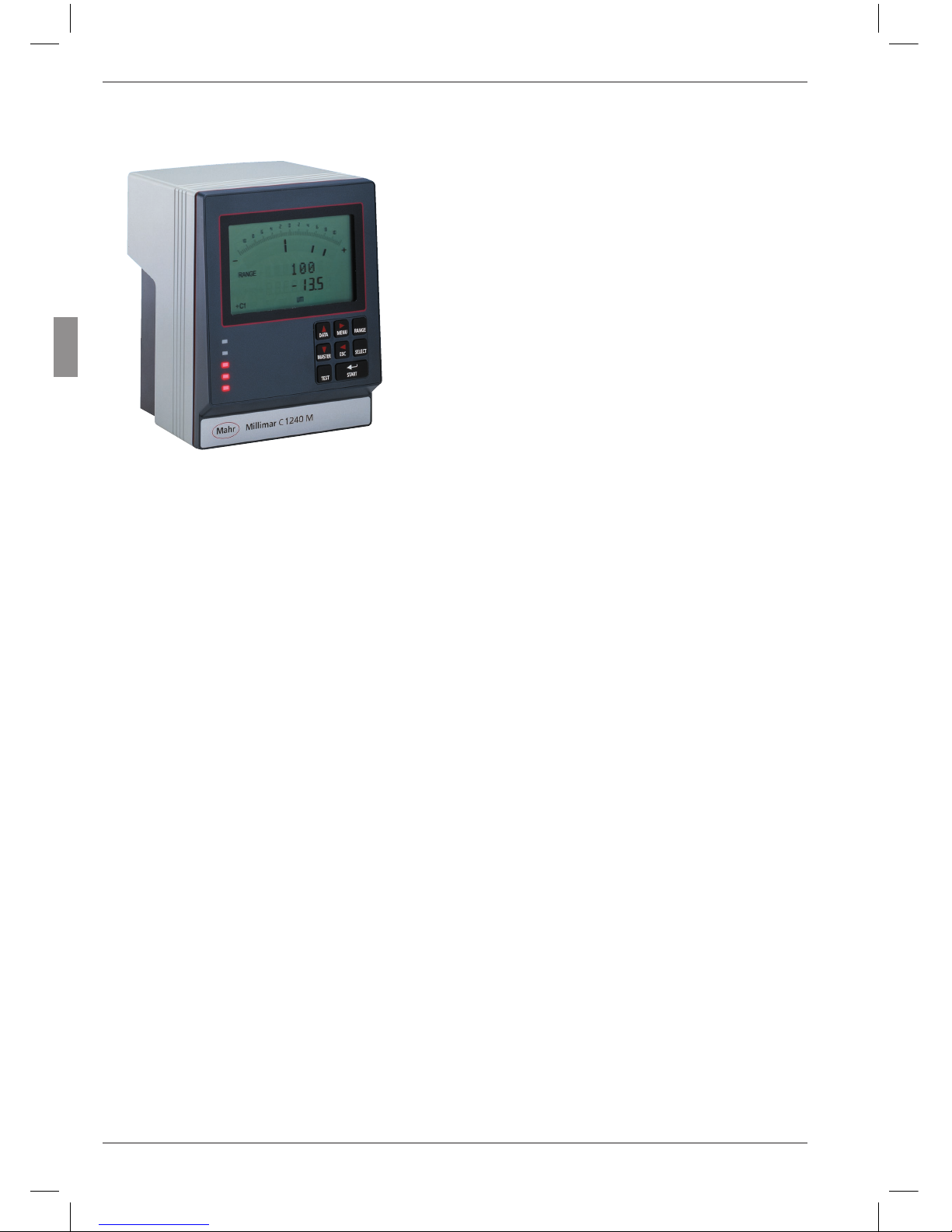
2 Control elements
Display (1)
All important measurement information is depicted on the display – measured value (analog
and digital), connection formula, display range
(not when 2 features are displayed simultaneously), measuring unit, indication of whether the
displayed value is a maximum, minimum, aggregate or differential value, and indication (letter
“T”) that the measured value memory is active
(if applicable).
It also displays the catalog of functions and parameters.
Keypad (2)
The keypad comprises 8 keys. Four keys are used
to navigate Millimar’s catalog of functions and
parameters (DATA, MENU, MASTER and ESC).
Fig. 1
Front of Millimar C 1208/C 1216/C 1240
1 Display
2 Keypad
3 Status lamps
13
Mahr GmbH, Millimar C1208/C1216/C1240
MENU
Displays Millimar’s catalog of functions and parameters.
In the catalog of functions and parameters itself,
this key is used to switch between subfunctions
and enter numerical values.
When entering numerical values, this key is used
to move from one digit to the next (to the right).
The selected digit flashes to show that it can be
changed.
DATA
Used to navigate the catalog of functions and
parameters and to begin data transfer.
Within a function level of this catalog, this key is
used to scroll up in order to show further functions/settings.
When setting numerical values, this key is used
to increase the value of the flashing (and therefore selected) digit by 1. If the number 9 is displayed when the DATA key is pressed, this will
change to 0.
i
Press the START key to stop entry
of numerical values. The numerical
value that has been entered flashes.
Press the START key again to adopt
the numerical value.
If the DATA key is pressed at the end of a measurement and the interface has been set appropriately, data is transferred to a connected PC,
see Chapter 14.
MASTER
In measuring mode, this key is used to start a
master measurement.
In the catalog of functions and parameters, this
key is used within the selected function level to
scroll down in order to show further functions/
settings.
When setting numerical values in the catalog of
functions and parameters, this key is used to decrease the value of the flashing (and therefore
selected) digit by 1. If 0 is displayed when the
MASTER key is pressed, this will change to the
number 9.
i
Press the START key to stop entry
of numerical values. The numerical
value that has been entered flashes.
Press the START key again to adopt
the numerical value.

14
Mahr GmbH, Millimar C1208/C1216/1240
ESC
This key is used in the catalog of functions and
parameters to move from function sublevels to
the higher level.
When entering numerical values, this key is used
to move from one digit to the next (to the left).
The selected digit flashes to show that it can be
changed.
Pressing ESC when in setup mode exits this
mode.
Restoring factory settings
Pressing the ESC key immediately after switching
on the unit initializes the instrument, restoring all
the original factory settings. This is indicated by
“INITALL” appearing on the display.
— Hold down the ESC key when switching on
Millimar. The unit boots up and “INITALL”
is displayed. Once the boot-up process has
been completed “DEUTSCH (4.3.1)” flashes.
— Use the DATA and MASTER keys to set the
display language and press START (twice)
to adopt the selected language. “MM (4.4.1)“
flashes.
— Use the DATA and MASTER keys to set the
measuring unit and press START (twice) to
adopt the selected unit. “MAHR“ appears on
the display, followed by the standard display
elements.
15
Mahr GmbH, Millimar C1208/C1216/C1240
* additional settings for C 1216 / C 1240 instruments
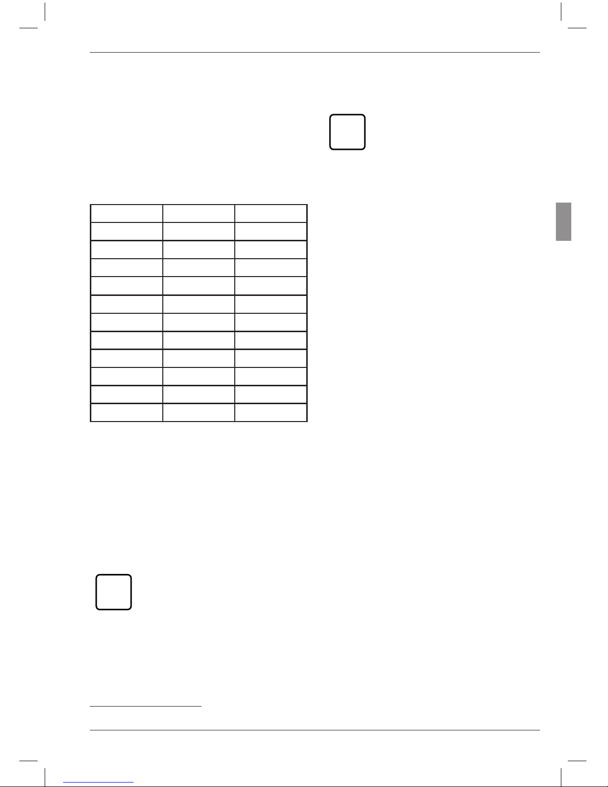
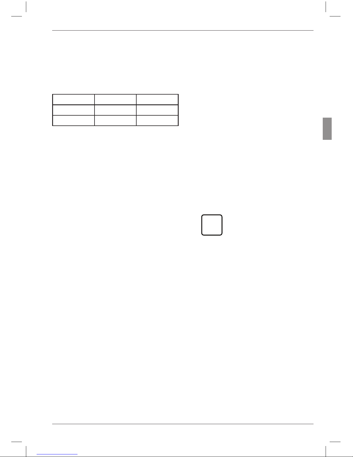
RANGE
Opens the selection list in which the size of the
display range can be selected. The increments of
the analog scale and the number format of the
numerical display are changed accordingly. The
following increments are available for the different measuring units:
mm µm inch
10 10 000 0.3
3 3 000 0.1
1 1 000 0.03
0.3 300 0.01
0.1 100 0.003
0.03 30 0.001
0.01 10 0.0003
0.003 3 0.0001
0.001* 1* 0.00003*
0.0003* 0.3* 0.00001*
I — — — — — I I — — — — — I I — — — — — I
"I — — — — — I“ stands for “tolerance limited”.
This means that the display range depicts the
range between the lower and upper tolerance
limit. This can be used with the analog display to
quickly identify where the current measured value lies in the tolerance range. This enables trends
(e.g. ever larger dimensions) to be rapidly identified, enabling appropriate countermeasures to
be implemented.
i
As tolerance ranges vary, the lettering of the analog scale (the numerical values) is removed.
i
The unit of measurement of the
display (mm, µm or inch) cannot
be changed with this key. If an alternate unit of measurement is required for the display, this has to be
selected via the catalog of functions
and parameters under “SETTING”
--> “UNIT”. The current measuring
unit is indicated in the bottom line
of the display.
16
Mahr GmbH, Millimar C1208/C1216/1240
SELECT
This key is freely programmable. Up to six frequently used functions or subfunctions can be
assigned to this key.
To assign a function to the key, simply select
the required function in the catalog of functions
and parameters and press the SELECT key. The
message “SELECT x” appears, whereby the “x”
stands for one of the key’s six memory locations
.
i
It is not possible to save different
parameter values (e.g. the factor
“0.3”) or settings (e.g. the measuring
unit “MM”) to the SELECT key.
If SELECT is pressed in measuring mode, the
function assigned to memory location 1 is displayed. Continually pressing SELECT scrolls
through the other functions saved to the key.
Press MENU to make parameter settings or enter numerical values for the selected function.
Settings and values are selected, changed, set,
and accepted as indicated in the catalog of functions and parameters.
If all the assignments of the key are to be deleted, select “SETTING” --> “CLR-SEL (4.8)”
in the catalog of functions and parameters then
press the MENU key. Answer the Safety inquiry
by pressing START.
i
Press ESC to exit deletion of SELECT
key assignments. The DATA and
MASTER keys have no effect here.

17
Mahr GmbH, Millimar C1208/C1216/C1240
TEST (indication of raw values)
This function is required for moving and correctly positioning (i.e. setting up) the probe in the
measuring device as the current position of the
probe(s) is indicated directly i.e. without being
multiplied by a factor or corrected by the master
correction value.
The measured value of channel C1 is indicated
on the analog scale and in the upper line of the
numerical display. The measured value of C2 is
indicated in the lower line of the numerical display.
On pressing either the DATA or MASTER key,
the word CALIBRA. and the currently set display range are indicated. If one of the two keys
is pressed again, the display range is enlarged
or reduced according to the programmed increments and the scaling of the analog scale and
the number format of the numerical display are
changed accordingly.
Press either the ESC or START key to exit setup
mode.
START
This key is used to select settings or set numerical values in the catalog of functions and parameters. The most recently selected settings
and numerical values flash. Press the START key
again to adopt the flashing settings. The display
then moves to the next level up in the catalog of
functions and parameters. The changed settings
are used for the next measurement.
Press START in the first (1., …, 4.) or second (1.1,
…, 4.9) function level to exit the catalog of functions and parameters.
Pressing START in setup mode (TEST) exits
setup mode.
Depending on the settings selected under
“PROCESS“ (of measurement), pressing START
initiates individual measurements or measuring
cycles. If the appropriate settings have been selected, START can also be used to end measure-
ments (see Chapter 10.2).
Status lamps (3)
These are used to indicate the positioning of the
current measured value or result in relation to
the tolerance limits. The colors used to indicate
values that are within tolerances, that are borderline, or that breach tolerances can be selected in
the catalog of functions and parameters under
“FEATURE”--> “TOLERNCE”--> “COLOR”.
18
Mahr GmbH, Millimar C1208/C1216/1240
Serial RS 232 interface (rear side of Millimar)
A printer or computer can be connected to this
9 channel interface. If necessary (e.g. if the measured value memory is full and there is a risk that
the first entry will be overwritten by the most
recent), data that has already been acquired can
be printed out on a connected printer and then
deleted.
If a computer is connected, the following processes can be executed depending on the setting of the Millimar interface
– Measured values can be transferred to, or
queried from, the computer
– Parameter settings can be changed or que-
ried by the computer
– Measurements can be initiated or terminat-
ed by the computer.
Data saved on the computer can be processed
using appropriate programs (statistics programs,
QA programs) – see Chapter 14 “Using the serial
interface (RS 232)”.
Parallel interface (rear side of Millimar)
The 25-pin interface marked with “I/O” enables
data to be transferred to and from other instruments in the Millimar range (e.g. footswitches)
or a programmable controller for e.g. automatic
sorting processes (see Chapter 15 “Using the
parallel I/O interface”).
Connection for power supply unit (rear
side of the Millimar )
The power supply unit is plugged into the connection marked with “9 V =”. This power supply
unit covers a voltage range between 100 V and
240 V and a frequency range of between 47 Hz
and 63 Hz.
i
No other power supply must be
used.
On/off switch (rear side of the Millimar)
Millimar is switched on and off using the on/off
switch.
Once the unit has been switched on, the software boots and the display indicates in sequence the type of instrument (C 1208 C 1216
or C 1240), the software version number, the
compatibility of the probe inputs, and finally the
standard display elements.
19
Mahr GmbH, Millimar C1208/C1216/C1240
3 Performing basic settings
8. Press START again to adopt the flashing
display language. The display then returns
to the catalog of functions and parameters
item “LANGUAG. (4.3)”.
i
If at this point either the MASTER or DATA key is pressed
instead of START, the display
returns to the language selection list (cf. point 6). An alternative display language can be
selected.
9. If no further settings are to be made in the
catalog of functions and parameters, press
the START key. The standard display ele-
ments appear.
If further settings are necessary, navigate
to the appropriate point of the catalog of
functions and parameters using the ESC,
MASTER, DATA and MENU keys and carry
out the settings as required.
3.1 Selecting the display language
The information, functions and settings that appear on the Millimar display are available in the
following languages :
German English French
Spanish Italian Portuguese
Swedish
The appropriate language can be selected when
commissioning the instrument (see Chapter
“Initial commissioning”). However, the language
selection made at this point can be changed at
any time. To do this:
1. Press the MENU key when the standard
display elements are shown. The catalog of
functions and parameters is opened and the
setting “FEATURE (1)” is displayed.
2. Use the DATA and MASTER keys to select
the setting “SETTING (4)”.
3. Press MENU again. The setting “DISPLAY
(4.1)” is displayed.
4. Use the DATA and MASTER keys to select
the setting “LANGUAG. (4.3)”.
5. Press MENU again. The most recently se-
lected language setting flashes.
6. Use the DATA and MASTER keys to select the new display language (ENGLISH,
FRANC., ITAL., ESPANOL, PORTUG.,
SVENSKA or DEUTSCH).
7. Press START. The selected display language
flashes.

20
Mahr GmbH, Millimar C1208/C1216/1240
3.2 Setting the contrast
The contrast can be adjusted to the light conditions of the location. On delivery, contrast is set
to medium. However, this can be changed at any
time. To do this:
1. Press the MENU key when the standard
display elements are shown. The catalog of
functions and parameters is opened and the
setting “FEATURE (1)” is displayed.
2. Use the DATA and MASTER keys to select
the setting “SETTING (4)”.
3. Press MENU again. The setting “DISPLAY
(4.1)” is displayed.
4. Press MENU again. The setting “FEATURE
(4.1.1)” is displayed.
5. Use the DATA and MASTER keys to select
the setting “CONTR. (4.1.3)”.
6. Press MENU again. Setting “CONT.+/-”
and the numerical value of the current contrast setting are displayed.
7. Use the DATA and MASTER keys to select
the new contrast (16, 13, .….., 1, 0).
i
The highest contrast setting is
“16” and the lowest “1”. When
“0” is selected, the display becomes blank. This setting is not
recommended!
8. Press START. The numerical value of the
contrast setting that has been selected flashes.
9. Press START again to adopt the flashing
contrast setting. The display then returns
to the catalog of functions and parameters
item “CONTR. (4.1.3)”.
i
If at this point either the DATA
or MASTER key is pressed instead of START, the dis play
returns to the contrast set ting
selection list (cf. point 7). The
contrast can be changed again.
10. If no further settings are to be made in the
catalog of functions and parameters, press
the START key. The standard display ele-
ments appear.
If further settings are necessary, navigate
to the appropriate point of the catalog of
functions and parameters using the ESC,
MASTER, DATA and MENU keys and carry
out the settings as required.
21
Mahr GmbH, Millimar C1208/C1216/C1240
3.3 Setting the unit of measurement
Tolerances are usually set for workpiece measurements and deviations using a specific unit of
measurement. To simplify checking, it is recommended that this specific unit of measurement is
also used to display measured values. Workpiece
measurements and deviations can be depicted
on the Millimar in the following units of measurement: millimeters, micrometers or inches.
The unit of measurement can be selected when
commissioning the instrument (see Chapter
“Initial commissioning”). However, the unit selected during this procedure can by changed at
any point. To do this:
1. Press the MENU key when the standard
display elements are shown. The catalog of
functions and parameters is opened and the
setting “FEATURE (1)” is displayed.
2. Use the DATA and MASTER keys to select
the setting “SETTING (4)”.
3. Press MENU again. The setting “DISPLAY
(4.1)” is displayed.
4. Use the DATA and MASTER keys to select
the setting “UNIT (4.4)”.
5. Press MENU again. The current unit of mea-
surement flashes.
6. Use the DATA and MASTER keys to select
the new unit of measurement (MM, INCH or
MICRON)
7. Press START. The selected unit of measure-
ment flashes.
8. Press START again to adopt the flashing unit
of measurement. The display then returns
to the catalog of functions and parameters
item “UNIT (4.4)”.
i
If at this point either the DATA
or MASTER key is pressed instead of START, the display
returns to the unit of measurement selection list (cf. point 6).
The unit of measurement can
be changed again.
9. If no further settings are to be made in the
catalog of functions and parameters, press
the START key. The standard display ele-
ments appear. The selected measuring unit
is indicated in the bottom line of the display
as mm, µm or inch.
If further settings are necessary, navigate
to the appropriate point of the catalog of
functions and parameters using the ESC,
MASTER, DATA and MENU keys and carry
out the settings as required.

22
Mahr GmbH, Millimar C1208/C1216/1240
3.4 Setting the resolution/display format of the measured value
The resolution of the numerical display can be
adjusted to match the type and size of the expected indicated value. To do this:
1. Press the MENU key when the standard
display elements are shown. The catalog of
functions and parameters is opened and the
setting “FEATURE (1)” is displayed.
2. Use the DATA and MASTER keys to select
the setting “SETTING (4)”.
3. Press MENU again. The setting “DISPLAY
(4.1)” is displayed.
4. Press MENU again. The setting “FEATURE
(4.1.1)” is displayed.
5. Use the DATA and MASTER keys to select
the setting “RESOL. (4.1.2)”.
6. Press MENU again. The (schematized) num-
ber of places before and after the decimal
point of the numerical display are indicated.
7. Use the DATA and MASTER keys to select
the new display format. The options are:
mm µm inch
ooo.oo ooooo o.oooo
ooo.ooo ooooo.o o.ooooo
ooo.oooo ooooo.oo* o.ooooo5
o.ooooo* o.oooooo*
8. Press START. The selected display format
flashes.
9. Press START again to adopt the flashing dis-
play format. The display then returns to the
catalog of functions and parameters item
“RESOL. (4.1.2)”.
i
If at this point either the DATA
or MASTER is pressed instead
of START, the display returns to
the display format selection list
(cf. point 7). The display format
can be changed again.
10. If no further settings are to be made in the
catalog of functions and parameters, press
the START key. The standard display ele-
ments appear.
If further settings are necessary, navigate
to the appropriate point of the catalog of
functions and parameters using the ESC,
MASTER, DATA and MENU keys and carry
out the settings as required.
* This format is only available for the Millimar C 1216/C 1240.
23
Mahr GmbH, Millimar C1208/C1216/C1240
3.5 Selecting the number of features/
test results to be displayed
Up to two features can be displayed simultaneously on Millimar. However, this is only possible
when static measurements are being carried out.
The number of features that are to be simultaneously displayed (either 1 or 2) must be specified
before measuring starts. To do this:
1. Press the MENU key when the standard
display elements are shown. The catalog of
functions and parameters is opened and the
setting “FEATURE (1)” is displayed.
2. Use the DATA and MASTER keys to select
the setting “SETTING (4)”.
3. Press MENU again. The setting “DISPLAY
(4.1)” is displayed.
4. Press MENU again. The setting “FEATURE
(4.1.1)” is displayed.
5. Press MENU again. The setting “1 FEAT.”
is displayed.
6. Use the DATA and MASTER keys to select
the feature display mode. The options are:
1 FEAT. One feature from one static or
dynamic measurement is displayed in the bottom line of the
numerical display.
2 FEAT. Two features from one static
measurement are displayed. One
is displayed in the top line of the
numerical display, one in the bottom line.
i
This, however, is
only possible up to
a certain point. The
Millimar switches
about four times
per second from on
probe channel to
the other and digitizes the encountered measured
value. Only suitable
for static measurements!
AUTODET From the two features of a static
or dynamic measurement just
one at a time is displayed in the
bottom line of the numerical display. The display switches from
one feature to the other when
the set area limits are exceeded
or fallen short of.

24
Mahr GmbH, Millimar C1208/C1216/1240
7. Press START. The selected feature display
mode flashes.
8. Press the START key again to adopt the
flashing mode. The display then returns to
the catalog of functions and parameters
item “FEATURE (4.1.1)”.
If at this point either the MASTER or DATA
key is pressed instead of START, the display
returns to the feature display mode selection
list (cf. point 7). The feature display mode can
be changed again.
9. If no further settings are to be made in the
catalog of functions and parameters, press
the START key. The standard display ele-
ments appear.
If further settings are necessary, navigate
to the appropriate point of the catalog of
functions and parameters using the ESC,
MASTER, DATA and MENU keys and carry
out the settings as required.
i
If the “2 FEAT.” or
“AUTODET” mode has been selected, changes will have been
applied to the standard display
elements and/or the catalog of
functions and parameters.
AUTODET
If this mode has been selected,
the FEAT.2 function appears
in the catalog of functions
and parameters in addition to
FEAT. 1 or FEATURE. The
DET LIM function is also avail-
able under FEAT.1 (1) and
FEAT.2 (2). This function en-
ables limits to be set for automatic feature detection.
2 FEAT.
If this mode has been selected,
the FEAT. 2 function appears in the catalog of functions
and parameters in addition to
FEAT. 1. The value of the second feature is indicated in the
top line of the numerical display
instead of the current display
range and the value of the first
feature is displayed in the bottom line.

25
Mahr GmbH, Millimar C1208/C1216/C1240
4 Positioning the probe in the measuring device (setup)
5. Move the probe by hand or using a positioning device if available, so that the measured
value is zero.
6. Clamp the probe in this position.
7. Press either the ESC or START key to exit
setup mode.
To use a probe to take measurements across the
full measuring range available, it has to be correctly positioned in the measuring instrument. If
this is not the case, the measuring range can be
exceeded or fallen short of.
1. Insert the probe into the measuring instrument.
2. Fit a setting master or a workpiece of known
size into the measuring instrument.
3. Press the TEST key.
The measured value transmitted by the
probe across channel C1 is depicted on the
scale and in the top line of the numerical display. If applicable, the bottom line of the numerical display depicts the measured value
transmitted by the probe across C2.
4. If the Millimar display range is too small or
large to allow the probe to be correctly positioned, it can be changed using the DATA
and MASTER keys. To do this: Press either
the DATA or MASTER key. The current display range is shown. Press one of the two
keys again to resize the display range in line
with the programmed increments and to
change the analog scale accordingly.
26
Mahr GmbH, Millimar C1208/C1216/1240
5 Aligning probe sensitivity
When calibrating the sensitivity of the probe connected to C1, the probe is used to record the
measured values at two measuring points that
are known to be a certain distance apart. Gage
blocks and setting masters of various sizes are
particularly suited to this purpose and can be
used to calibrate the entire measuring chain. This
means that production-related deviations in sensitivity affecting both the display and probe can
be measured and corrected. The setting masters and/or gage blocks should differ by at least
500 µm for a Millimar C 1216 with a measuring
range of ± 2000 µm. For measurements within
a range of ±200 µm, or for the Millimar C 1208
resp. C 1240, the difference should be at least
100 µm.
Probe sensitivity is subject to variations caused
during production. These variations are usually
less than 0.5 %. Deviations such as this can be
tolerated for many measuring tasks. In these
instances, there is no need to align sensitivity.
However, in the case of differential measurements (C1-C2), these deviations can distort measurement results to an unacceptable extent.
i
The sensitivity of the display is also
subject to variations caused during
production processes. If only the
Millimar display is to be calibrated,
a nominal value selector (e.g. the
1283 WN) can be attached to the
C 1208/C 1216/C 1240 instead of
the probe. However, to enable precise measurements, the entire measuring chain should be calibrated.
The C 1208/C 1216/C 1240 offers two options
for correcting these deviations – firstly, the signals of both probes/channels can be multiplied
with a common factor, or secondly, the sensitivity
of the probe connected to C1 can be determined
(calibrated) then the sensitivity of the probe connected to C2 aligned to that of the first probe.
27
Mahr GmbH, Millimar C1208/C1216/C1240
5.1 Calibrating a measuring channel
i
Three standards are required:
one for the zero point, one for
the positive indication value
and one for the negative indication value. A nonimal value
adjuster (e.g. Millimar 1283
WN) may be used instead of
the standards.
1. Press the MENU key. The catalog item
"FEATURE (1)" is displayed.
2. Press the DATA key. The catalog item
"SETTING (4)" is displayed.
3. Press the MENU key again. The catalog item
"DISPLAY (4.1)" is displayed.
4. Press the DATA key again. The entry
"CALIBR (4.9)" is displayed.
5. Press the MENU key. The entry "PASSWRD"
is displayed along with seven zeroes below
it. The first zero is flashing.
6. Enter the password (1 000 000) and confirm
with START. "CHAN 1 (4.9.1)" is displayed.
7. Press the MENU key. "ZERO LO" is dis-
played.
8. Adjust the value 0 on the nominal value adjuster and confirm with START. „OFFSET“
will be displayed for about 2 seconds and
then menu item „NEG VAL (4.9.1.1.1) together with a numerical value.
9. Use the MENU, DATA and MASTER keys
to set the numerical value displayed to the
negative value of the nominal value adjuster
and accept it with START.
10. Set the nominal value adjuster to the negative calibration value and confirm with
START. „POS VAL (4.9.1.1.1.1) is displayed.
11. Adjust the positive calibration value as detailed for the negative one (see points 9 and
10 of this description). „CHAN 1 (4.9.1) is displayed then.
12. A correction factor is calculated from the
measuring values and the nominal values
entered. In subsequent measurements, all of
the measuring values of the probe at C1 will
be multiplied by this factor.
i
Correction factors may lie in a
range between 0.3 and 3.0. If
the calculated factor exceeds
this range in either direction, the
previously set factor remains in
effect and the error message
"OUT LIM" is displayed.
13. If no other settings are to be made in the
catalog of functions and parameters, press
START. The current measuring value or result is displayed again.
To make further settings, use the ESC,
MASTER, DATA and MENU keys to navigate to the corresponding item in the catalog of functions and parameters and make
the required settings.
 Loading...