

Millett NuHybrid Assembly Instructions Manual

"NuHybrid" Solid-State Headphone Amplifier
Assembly instructions
What you need:
The bare PCB plus Korg Nutube 6P1 (from pmillett.com via eBay)
The parts (from Mouser)
A soldering iron and solder (Tin/Lead 63/37 is the easiest to work with - lead-free
solder is more difficult)
Wire cutters ("diagonal cutters")
DMM (Digital Multimeter)
The following are optional, but recommended:
Needle-nose pliers
To order the parts from Mouser, go to
http://www.mouser.com/ProjectManager/ProjectDetail.aspx?AccessID=b68a30231c, or go to the
"Tools" page at http://www.mouser.com/Tools/Tools.aspx and enter this access code in "Cart
Sharing" towards the bottom of the page: b68a30231c
The Mouser BOM includes all of the parts needed to build the NuHybrid except for the PCB
and the Korg Nutube, which are available from http://stores.ebay.com/pmillett. You can also
refer to the bill of materials at the end of this document for additional info.
Occasionally one of the parts on the BOM may be out of stock. The BOM has some
suggestions for alternate parts that can be used instead, as well as alternate parts that are
available from Digi-Key. Note that the Mouser BOM may be updated from time to time as
parts become difficult to source.
When assembling, keep the BOM and schematic handy, in case you have any questions
about what parts go where.
It is assumed that the builder has some basic electronics knowledge, like knowing which end
of the soldering iron to hold in the hand, and hopefully some experience building electronics.
However, this is a very easy project and is suitable for a first-time builder.
If you are new to soldering, it's highly recommended that you review one or more of the
excellent on-line soldering tutorials. Just search "soldering tutorial" on the web and/or
YouTube.
There is nothing sacred about the order that is listed for assembly. It can be convenient to
build starting with low-profile components, and work your way up to taller parts, so it's easier
to solder on the board backside. That is the way the instructions read. But you can install
parts in any order you want.
PCB Assembly
Step 1. Introduction
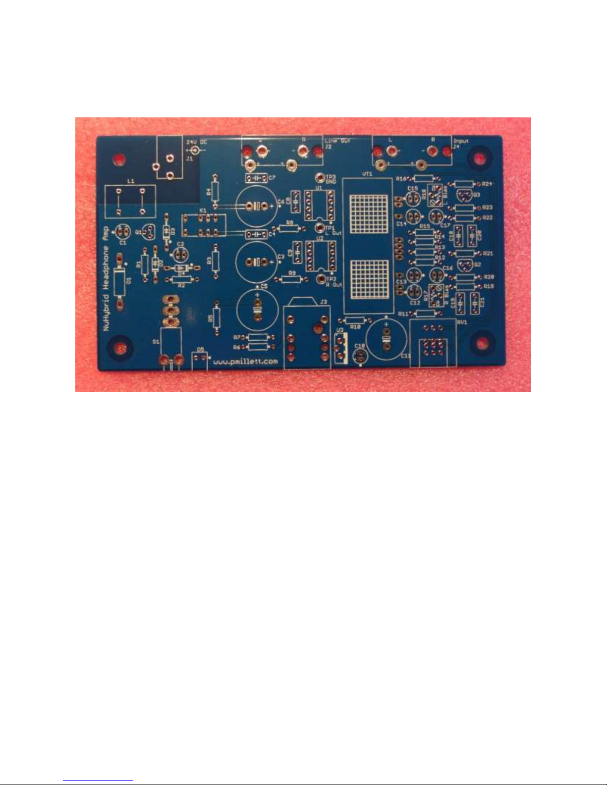
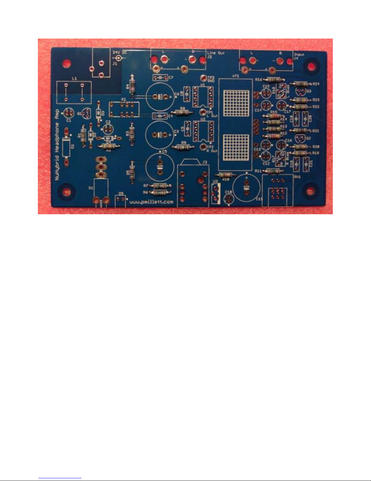
Start with familiarizing yourself with the bare PC board:
You'll see that each part has an outline silkscreened on the board, and a reference
designator (name) next to it. Parts are numbered starting at the lower left, so you can expect
to find resistor R1 somewhere near the lower left corner.
Some parts, like resistors, have no polarity and can be installed in either orientation. Others,
like diodes and electrolytic capacitors, need to be installed in a particular direction. These
parts have the orientation clearly marked on the silkscreen with a dot for the positive terminal
for capacitors, and a bar and dot for the cathode side of diodes.
2. Install resistors
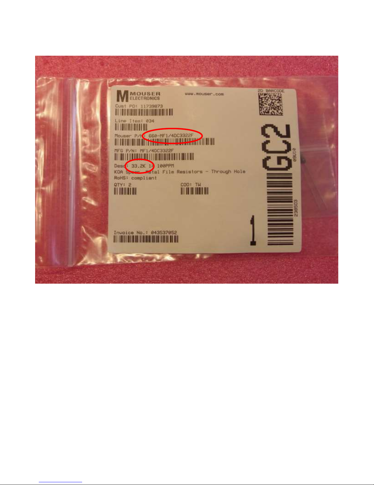
Each bag of parts from Mouser looks like this:
Match the Mouser part number or the description with the parts on the BOM. In this case,
you will see that 33.2k resistors are installed at R12 and R15.
Note that the resistors may be different colors.
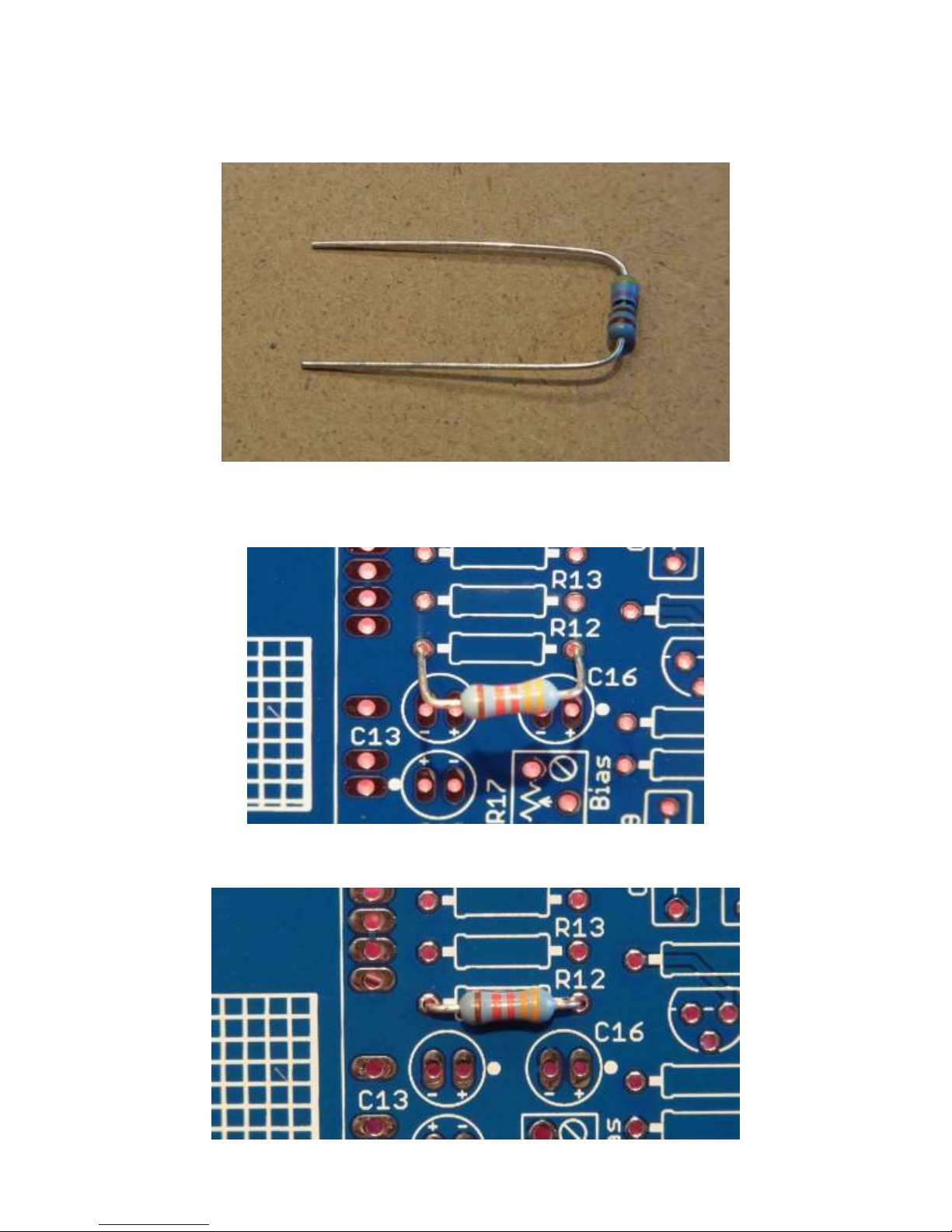
In no particular order, install the resistors. After you remove them from the bag, you'll need to
bend the leads (you can just use your fingers) so they look like this:
Next, insert them into the PCB in the appropriate spots:
Push them down flush with the board:
And bend the leads on the backside slightly:
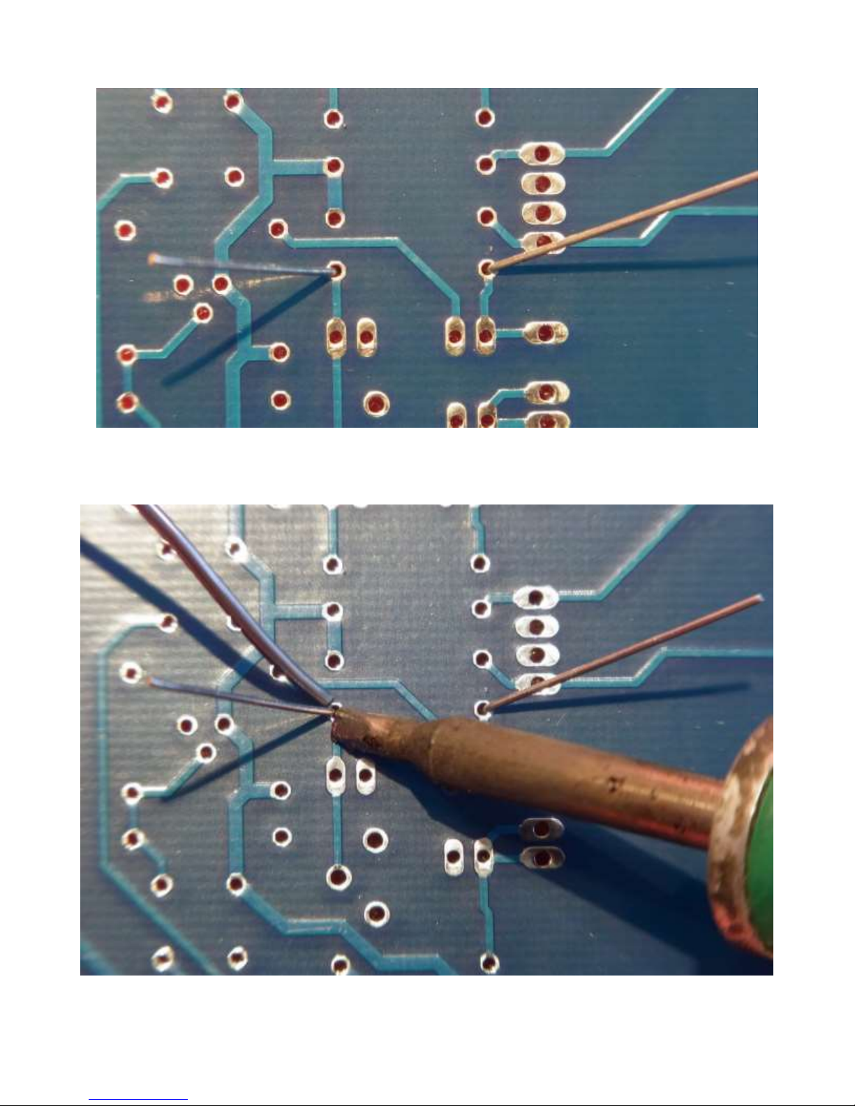
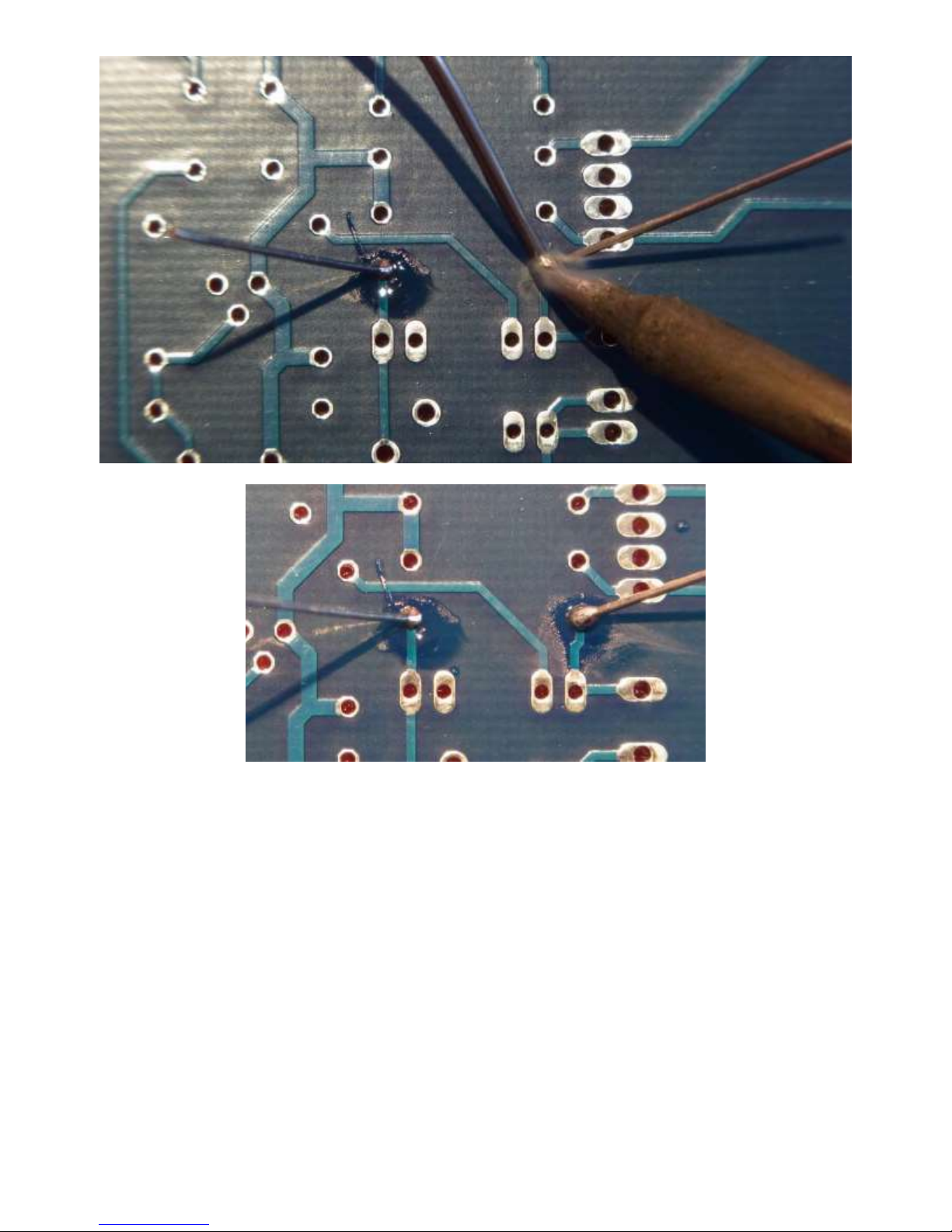
Next, solder the leads. Touch the soldering iron tip to both the pad and the lead, and apply a
little solder:
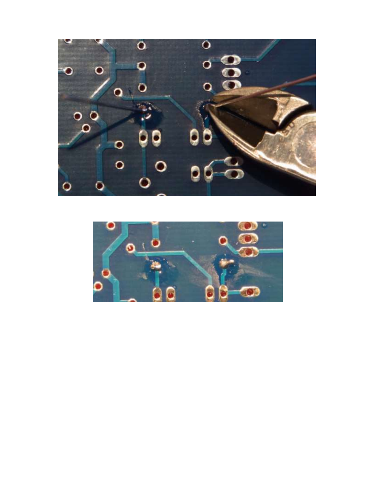
Next, using wire cutters ("diagonal cutters"), trim the excess wire leads:
It should wind up looking like this:
Now, repeat this process for all of the resistors.
When you’re done, the board should look like this:
2. Install diodes
The diodes are installed the same way as the resistors.
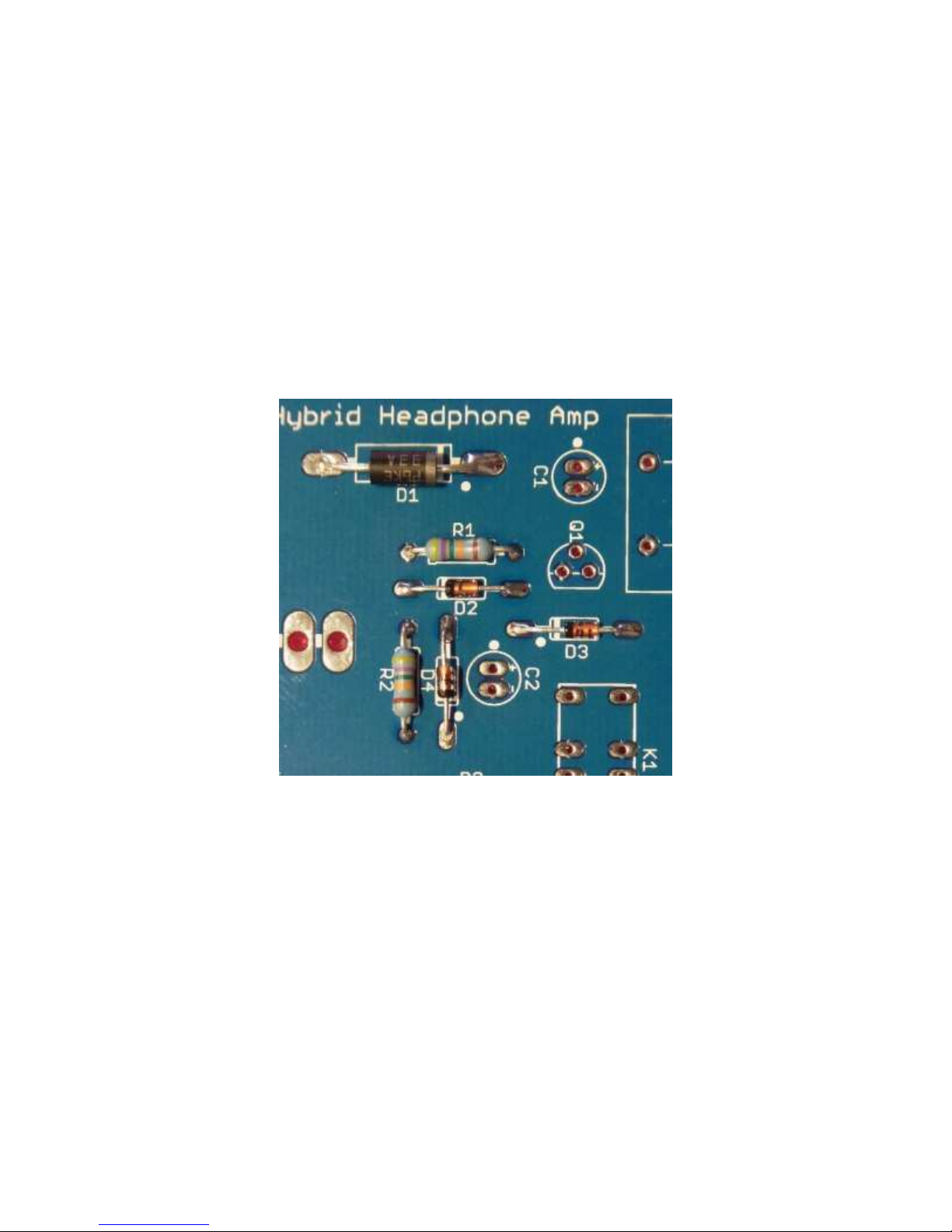
Diodes need to be installed in the correct orientation, so be careful and double-check to make
sure they are pointed the right way before soldering.
Note the diodes have a band on one end that matches with the band on the PCB silkscreen,
and the PCB also has a dot near that end.
Be careful, as the two 1N4148 diodes (D3 and D4) look virtually identical to the 1N5245B
Zener diode (D2)!
As with the resistors, bend the leads and solder, then trim the excess lead wires.
Check again that they are in the right way by matching them to this photo:
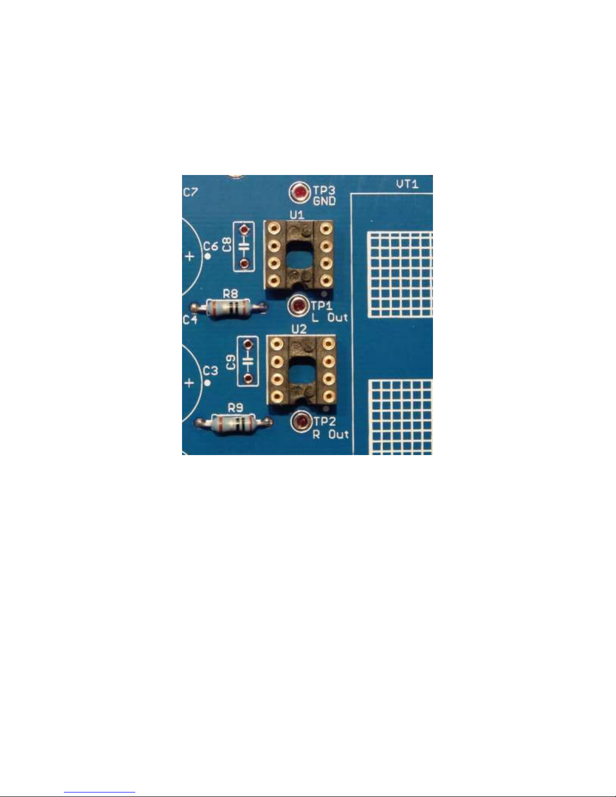
3. Install IC sockets
Two IC sockets are installed for the opamps, so you can change them to different ones if
desired. Note the orientation of the sockets - there is a small notch to indicate pin 1, which is
aligned with the PCB silkscreen:
 Loading...