

Miller Weldmaster T-100, T-500 User Manual

Chapter 1: Machine Overview
Section 1.1: Intended Use
The T-500 and T-100 are rotary hot air welders intended to heat
seal weldable thermal plastics such as:
-Vinyl (PVC) laminated fabrics
-Vinyl (PVC) coated fabrics
-Vinyl (PVC) films
-Polyurethane (PU) coated fabrics
-Polyurethane (PU) films
-Polypropylene (PP) coated fabrics
-Polyethylene (PE)
Page 1-1
-Thermoplastic Rubber (TPR) film
-Thermoplastic Rubber (TPR) fabrics
-Non-woven Polyester
-Non-woven Polypropylene
-Various Fusing Tapes
-Weldable Webbing
-Rigid Extruded Products
• The manufacturer does not approve of any other uses for these
machines.
• The manufacturer does not approve of the removal of any safety
guards while in operation.
• The manufacturer does not approve of any unauthorized modification of the machines.
• Only a properly trained technician may operate the T-500 and T-
100.
• Only a properly trained technician may perform any routine main-
tenance to the T-500 and T-100.
Chapter 1: Machine Overview | Section 1.1: Intended Use

Page 1-2
•Only a properly trained technician may perform any repairs to the T500 and T-100.
• Only manufacturer approved replacement parts are to be used for
the T-500 and T-100.
NOTE:The manufacturer will not be held liable for any damage or injuries occurring
from any inappropriate use of this machine.
Section 1.2: Electrical and Air Requirements
Warning! Only a qualified electrician may connect the
electrical power.
Module 1.2.1: Electrical Supply
The Miller Weldmaster T-500 and T-100 includes a power cord that
is approximately 6 feet in length. Due to the number of different
style outlets available, the cord will not include a plug. You may
choose to have your power cord hard wired into your power supply. It
is recommended that your electrician use a junction box with an on/
off switch.
The Miller Weldmaster T-500 and T-100 are available in both single
phase and three phase power, refer to your quotation for this
specification.
The Miller Weldmaster T-500 and T-100 require the following
electrical requirements:
• 208/240 volts
• 50Hz or 60Hz
• 40 amperes
If using the Miller Weldmaster T-500 and T-100 with a carriage,
this requires the following electrical requirements:
• 208/240 volts
• 50Hz or 60Hz
• 60 amperes
Module 1.2.2: Shop Air Supply
The Miller Weldmaster T-500 and T-100 include an In Shop Air
Supply Valve that allows quick connects and disconnects to your shop
air supply. Due to the number of different style airline connectors, a
male quick connect is not included. You will want to select a male
quick connect with a ¼ inch NPT (National Pipe Thread) to match
Chapter 1: Machine Overview | Section 1.2: Electrical and Air Requirements

your female quick connect.
The Miller Weldmaster T-500 and T-100 require the following shop
air requirements:
• Minimum of 65 psi at 3 cubic feet per minute.
•Not to exceed 125 psi.
• An in line water and dirt separator.
• It is not recommended to use an oiler for the air supply.
Section 1.3: Principles of Heat Sealing
Module 1.3.1: Heat
Hot Air
The heat required for the welding operation is created
electrically by two heating elements located inside the heat element
housing. The internal air compressor pumps air over the heat
elements and carries the heat through the hot air nozzle, applying
the heat to the material to be welded. The hot air temperature
ranges from 100 to 1350 Degrees Fahrenheit or 25 to 730 Degrees
Celsius.
Page 1-3
Hot Wedge
The heat required for the welding operation is created
electrically by heating elements located inside the wedge. Heat
dissipates through the aluminum core of the wedge, to the contact
area, applying heat to the material to be welded. The temperature
ranges from 100 to 900 Degrees Fahrenheit or 25 to 490 Degrees
Celsius.
Module 1.3.2: Speed
The speed of the weld rollers determines the amount of time the
heat is applied to the material being welded. The slower the speed
setting, the less heat needed to be applied to the material. The
faster the speed setting, the more heat will have to be applied to the
material. To achieve the best weld, a minimal amount of heat should
be applied to the material while still achieving a full weld. Too much
heat will cause distortion of the material while not enough heat will
prevent the material from welding.
Module 1.3.3: Pressure
The pressure of the weld rollers is the final step when creating a
weld. The pressure of the weld rollers compresses the heated
Chapter 1: Machine Overview | Section 1.3: Principles of Heat Sealing
Page 1-4
material together completing the welding process.
Module 1.3.4: Summary
When heat sealing, the correct combination of heat, speed, and
roller pressure will allow you to achieve a properly welded seam.
Section 1.4: Transportation, Specifications, and Storage
Warning! It is recommended to use a forklift when moving a
crated machine or removing crated machine from pallet.
Module 1.4.1: Transporting Within Production Facility
Due to the weight of the Miller Weldmaster T-500 and T-100, the
manufacturer requires a forklift or tow motor to be used. The forks
are to be inserted below the bottom frame along the center of
gravity. Lift slowly to insure proper placement of forks.
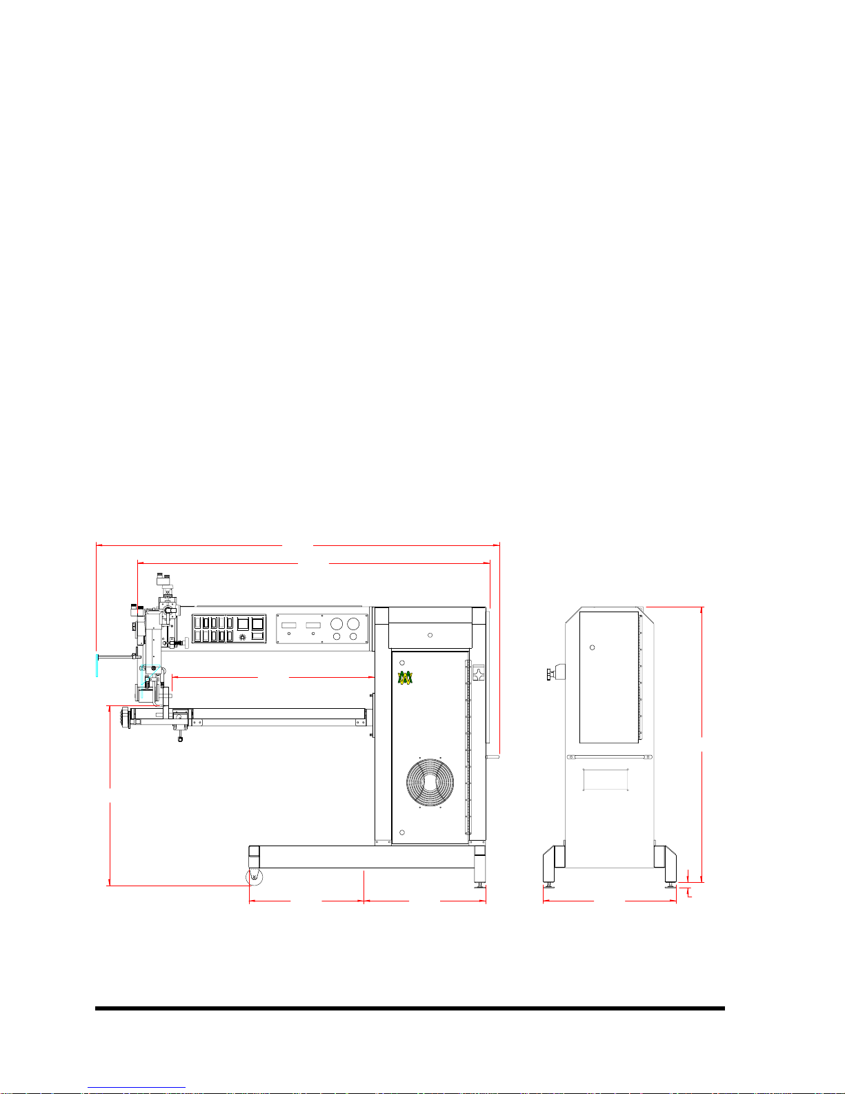
Figure 1.1: T-100
32.500
36.625
72.843
63.603
Center of Gravity
Units in Inches
MILLER
WELDMASTER
CORPORATION
T-100
22.00020.750
24.000
49.750
1.000
Chapter 1: Machine Overview | Section 1.4: Transportation, Specifications, and Storage
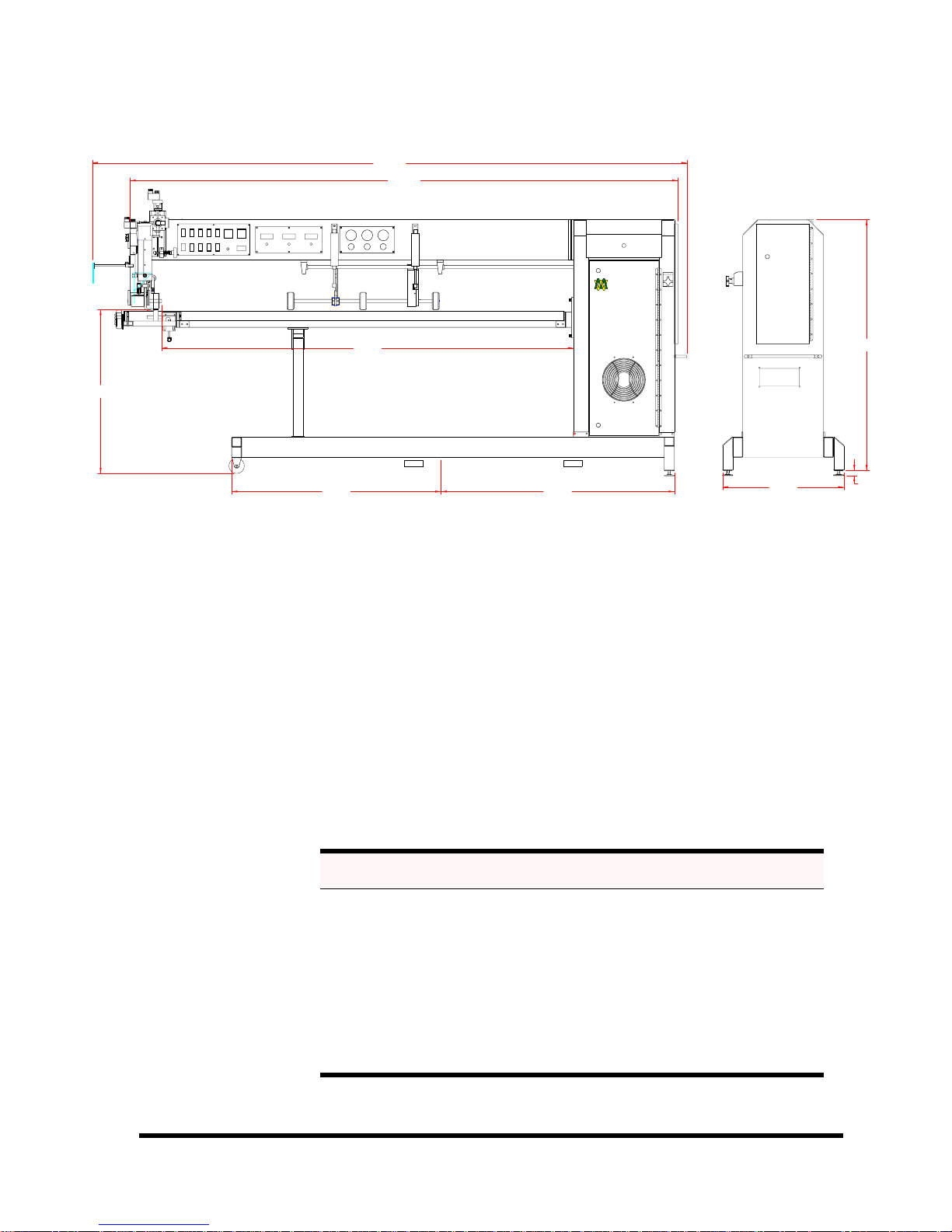
Figure 1.2: T-500
117.843
108.603
MILLER
WELDMASTER
CORPORATION
T-500
Page 1-5
32.500
81.625
ForkFork
46.25041.500
Center of Gravity
Units in Inches
24.000
Module 1.4.2: Transporting Outside Production Facility
The manufacturer requires the Miller Weldmaster T-500 and T-100
be placed on a pallet using a forklift or tow motor. The forks are to
be inserted below the bottom frame along the center of gravity.
Secure the machine to the pallet. To protect the various controls and
features, crate the machine. When loading into a truck for
transportation, use a forklift or tow motor.
Module 1.4.3: Storage
The manufacturer recommends that any time the machine is not
in use, it must be protected from excess dust and moisture.
49.750
1.000
Chapter 1: Machine Overview | Section 1.4: Transportation, Specifications, and Storage
Table 1-1:
Specifications T-100 T-500
Approximate Weight 510 lbs 780 lbs
Approximate Crated Weight 800 lbs 1090 lbs
Crated Width 32 in 32 in
Crated Length 75 in 120 in
Crated Height 65 in 65 in
Noise level during operation 90 dB(A) 90 dB(A)
Page 1-6
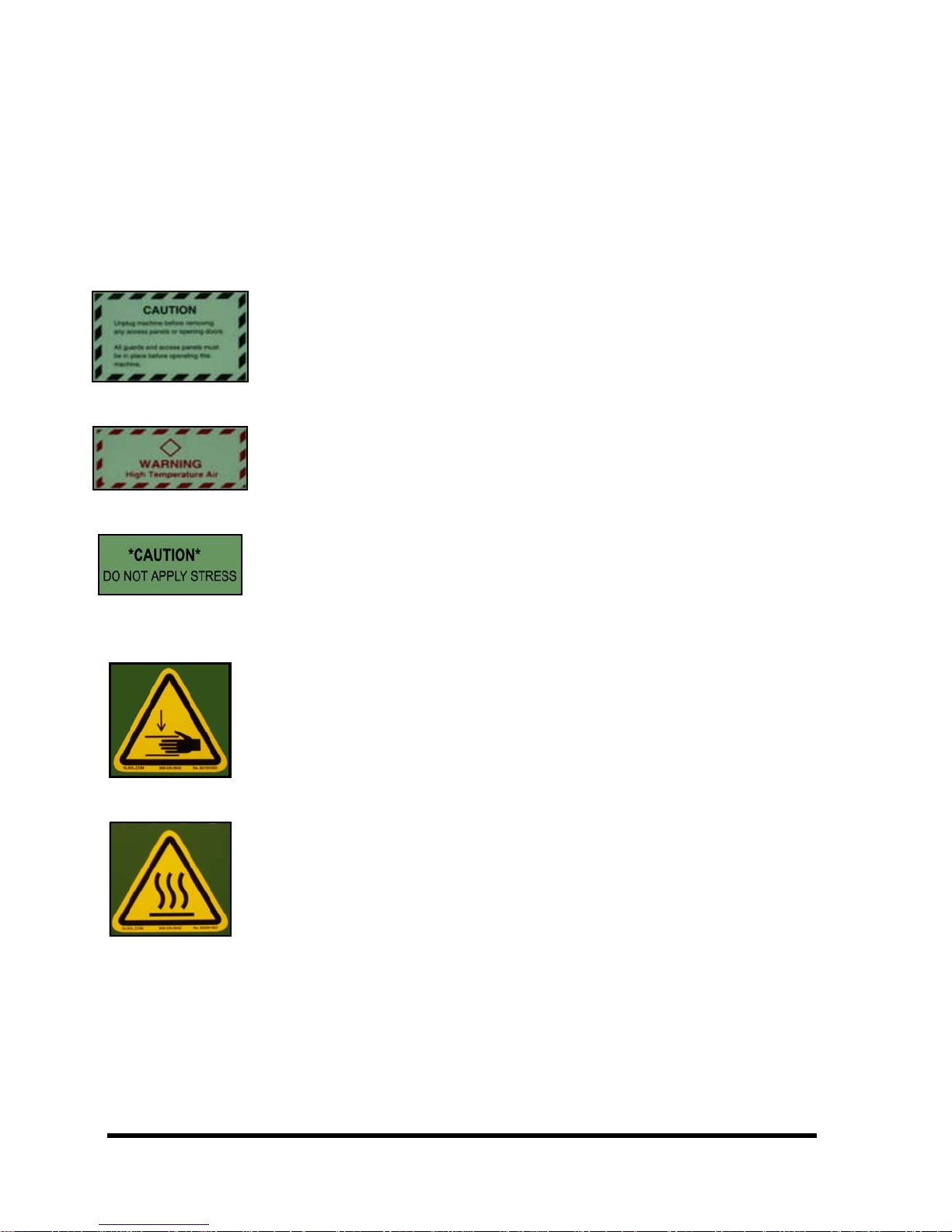
Section 1.5: Explanation of Symbols
There are several different warning symbols placed on the Miller
Weldmaster T-500 and T-100. These symbols are to alert the operator
of potentially hazardous areas on the machine. Familiarize yourself
with the their placement.
Figure 1.3: Caution, Unplug Machine…
The Caution, Unplug Machine sticker is placed near the opening of
the cabinet and all access panels. To prevent electrocution, the
welder should always have the power disconnected before the cabinet
door is opened.
Figure 1.4: Warning, High Temperature Air...
The Warning High Temperature Air sticker is placed on the Heater
Assembly. The T-500 and T-100 are capable of temperatures reaching
1350 degrees F.
Figure 1.5: Caution, Do Not Apply Stress...
The Caution, Do Not Apply Stress sticker is placed on the Heater
Assembly. Do not apply any unnecessary force on this part of the T500 and T-100.
Figure 1.6:
Pinch Points...
The Pinch Point decal is placed on the protective guard of the T100 and T-500. The symbol is to alert the user of the pinch point of
the two weld rollers.
Figure 1.7: Heat...
The Heat decal is placed on the protective guard of the T-100 and
T-5 0 0. Th e sy mb ol i s t o al er t th e us er o f t he h ot a ir or h ot w ed g e.
Chapter 1: Machine Overview | Section 1.5: Explanation of Symbols
Page 1-7
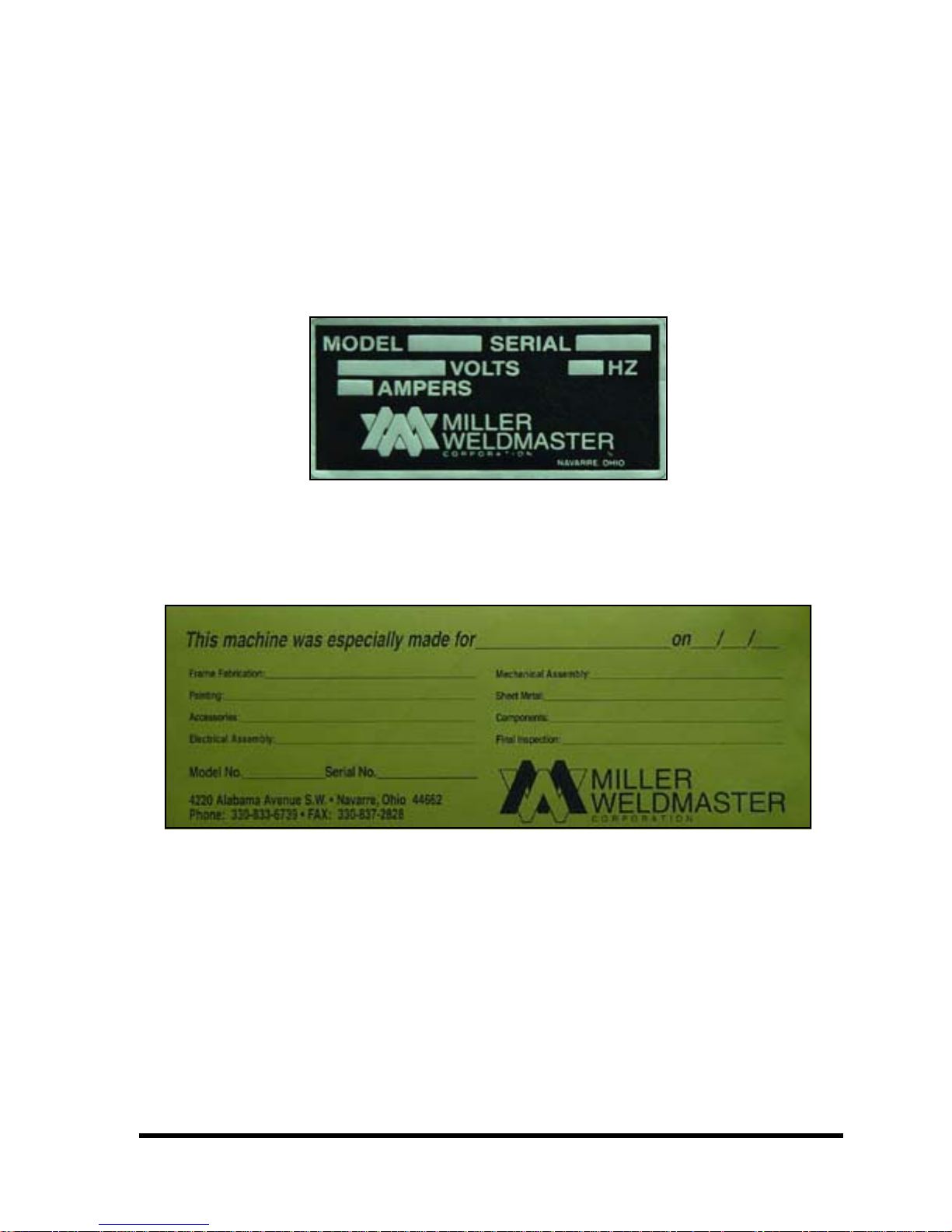
About Your Miller Weldmaster
Each Miller Weldmaster has this sticker located on the rear of the
machine. It identifies the model number and serial number of each
welder. It will also state the voltage, amperes, and hertz required
for operation.
Figure 1.8: Model & Serial Number Tag
At Miller Weldmaster, we take pride in the quality and
craftsmanship that goes into each machine. Each welder is built
specifically to your needs. Each technician that helped to
manufacture your welder is proud to leave his or her signature.
Figure 1.9: Quality Control Sticker
NOTE: Contact information is listed here, for your convenience.
Chapter 1: Machine Overview | Section 1.5: Explanation of Symbols
Page 1-8
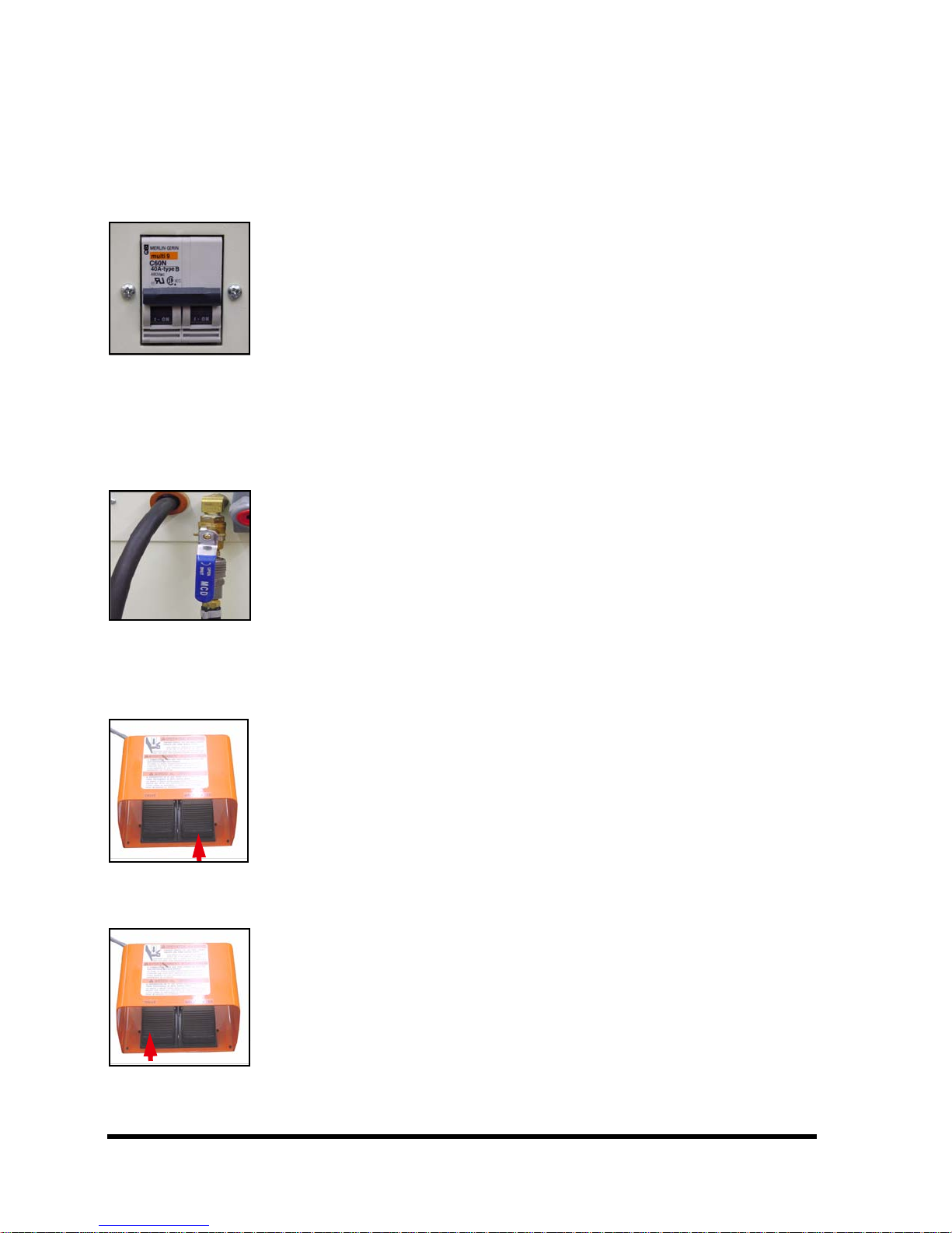
Section 1.6: Controls: Purposes and Functions
Figure 1.10:
Circuit Breaker Circuit Breaker
The purpose of the Circuit Breaker is to protect the machine if a
short were to occur somewhere in the system. It is also used to
disconnect the machine from the power source if needed.
Flipped to the on position, the Circuit Breaker will supply the
machine with electricity for operation.
Flipped to the off position, the Circuit Breaker will prevent the
supply of electricity to the machine.
Figure 1.11:
In Line Shop Air
Valve
In Line Shop Air Valve
The purpose of the In Shop Air Supply Valve is to connect and
disconnect the shop air supply to the machine.
Figure 1.12:
Weld Roller Foot
Switch
Figure 1.13:
Drive Foot Switch
Tu rn e d to th e o pe n p os i ti on as sh ow n
run the pneumatics of the machine.
Tu rn e d to th e o ff po si t io n, sh o p ai r w il l b e c ut of f f ro m t he
machine. This will disable the machine from working properly.
(Figure 1.11), shop air will
Weld Roller Foot Switch
The purpose of the Weld Roller Foot Switch is to control the
raising and lowering of the weld rollers.
Engaging or depressing the Weld Roller Foot Switch will raise the
top weld roller assembly.
Disengaging or releasing the Weld Roller Foot Switch will lower
the top weld roller assembly in a controlled manner.
Drive Foot Switch
The purpose of the Drive Foot Switch is to begin and end the
welding process. When the Drive Foot Switch is depressed, the heat
source will swing into place and the weld rollers and puller rollers
will begin to turn.
When the Drive Foot Switch is released, the heat source will
Chapter 1: Machine Overview | Section 1.6: Controls: Purposes and Functions
return to the static position and the weld rollers and puller rollers
will cease to rotate.

Figure 1.14:
Power Switch Power Switch
The purpose of the Power Switch is to turn the machine on and
off.
When using hot air, if the Power Switch is turned to the on
position, the internal air compressor will run if the drive system is
ready for operation.
When using hot wedge if the Power Switch is turned to the on
position, the drive system is ready for operation.
When using hot air and the Power Switch is turned to the off
position, the machine will continue to run for approximately 3
minutes through a cool down cycle and then automatically shut off.
When using hot wedge and the Power Switch is turned to the off
position, the machine will immediately shut off
Figure 1.15:
Hot Air Switch Hot Air Switch
The purpose of the Hot Air Switch is to control the power supply
to the hot air temperature controller, w h i c h g e ne r a t es h e at f ro m th e
heat elements.
Page 1-9
When the Hot Air Switch is turned to the on position, the
temperature controller will be activated and begin raising the
temperature to the preset temperature. It will take approximately
3-5 minutes for the temperature to reach the set point.
When the Hot Air Switch is turned off, the hot air temperature
controller will shut down and power will be removed from the heat
elements.
Figure 1.16: Wedge Switch
Wed ge S wit ch
The purpose of the wedge switch is to control the power supply to
the wedge temperature controller, which generates heat to the
wedge.
When the wedge switch is turned to the on position, the wedge
temperature controller will be activated and begin raising the
temperature to the preset temperature. It will take approximately
3-5 minutes for the wedge to reach the set point.
When the wedge switch is turned off the wedge temperature
controller will shut down and power will be removed from the
wedge.
Chapter 1: Machine Overview | Section 1.6: Controls: Purposes and Functions

Page 1-10
Figure 1.17:
Heat Swing
Switch
Heat Swing
The purpose of the Heat Swing Switch is to control the swing
action of the heat swing assembly.
When the Heat Swing Switch is turned to the on position, the heat
source will automatically swing into position for welding operation
when the Drive Foot Switch is depressed.
When the Heat Swing Switch is turned to the off position, the
heat source will remain in the static position when the Drive Foot
Switch is depressed.
Figure 1.18:
Drive Switch Drive Switch
The purpose of the Drive Forward/Reverse Switch is to control
the rotational direction of the weld rollers and puller rollers.
When the Drive Switch is turned to the forward position, the weld
rollers and puller rollers will rotate in the welding direction, when
the Drive Foot Switch is depressed.
When the Drive Switch is turned to the reverse position, the weld
rollers and puller rollers will rotate in the opposite or reverse
direction when the Drive Foot Switch is depressed. The hot air nozzle
will not swing into position in the reverse setting. The hot wedge
however, will for maintenance purposes.
Figure 1.19:
Override Switch Override Switch
The purpose of the Override Switch is to engage the complete
welding process without using the Drive Foot Switch.
When the Override Switch is turned to the run position, the heat
source will swing into place and the weld rollers and puller rollers
will turn for welding operation, as if the Drive Foot Switch were
depressed.
When the Override Switch is turned to the stop position, the heat
source will swing out and the weld rollers and puller rollers will cease
to rotate, stopping the welding operation as if the Drive Foot Switch
were released.
Chapter 1: Machine Overview | Section 1.6: Controls: Purposes and Functions
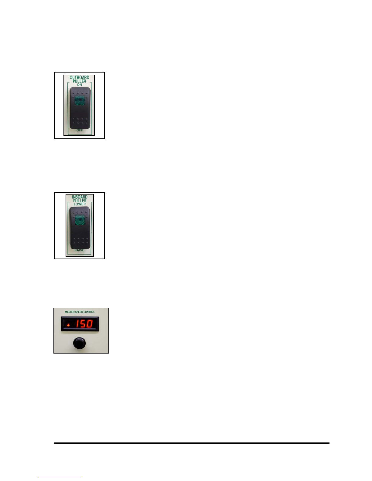
Figure 1.20:
Outboard Puller
Switch
Figure 1.21:
Inboard Puller
Switch
Page 1-11
Outboard Puller Switch
The purpose of the Outboard Puller Switch is to control the
Outboard Puller Assembly, which assists moving material from the
welding area, in conjunction with the double roller beam.
When the Outboard Puller Switch is turned to the on position, the
Outboard Puller Assembly will automatically lower into the pulling
position and the puller rollers will rotate when the Drive Foot Switch
is engaged.
When the Outboard Puller Switch is turned to the off position, the
Outboard Puller Assembly will remain in the raised position when the
Drive Foot Switch is engaged. The puller rollers will not rotate.
Inboard Puller Switch
The purpose of the Inboard Puller Switch is to control the Inboard
Puller, which assists feeding material into the welding area, in
conjunction with T-500 welders with a double roller beam.
When the Inboard Puller Switch is turned to the lower position,
the inboard puller assembly will automatically lower itself to the
pulling position. The rollers will turn when the Drive Foot Switch is
engaged.
When the Inboard Puller Switch is turned to the raise position,
the Inboard Puller Assembly will return to the raised position. The
puller rollers will not rotate when the Drive Foot Switch is engaged.
Figure 1.22: Master Speed Control
Master Speed Control
The purpose of the Master Speed Control is to control the speed
of the weld rollers and puller rollers during the welding process.
By turning the Master Speed Control dial clockwise, the speed of
the weld rollers and puller rollers will increase.
By turning the Master Speed Control dial counter clockwise, the
speed of the weld rollers and puller rollers will decrease.
Outboard Puller Sync
The purpose of the Outboard Puller Sync Control is to synchronize
the outboard puller rollers to the weld rollers. The Outboard Puller
Sync numbers are only used as a reference and do not have any
relationship and should not match the master speed control settings.
By turning the Outboard Puller Sync Control dial clockwise, the
Outboard Puller will increase in speed in relation to the weld rollers.
Chapter 1: Machine Overview | Section 1.6: Controls: Purposes and Functions
Page 1-12
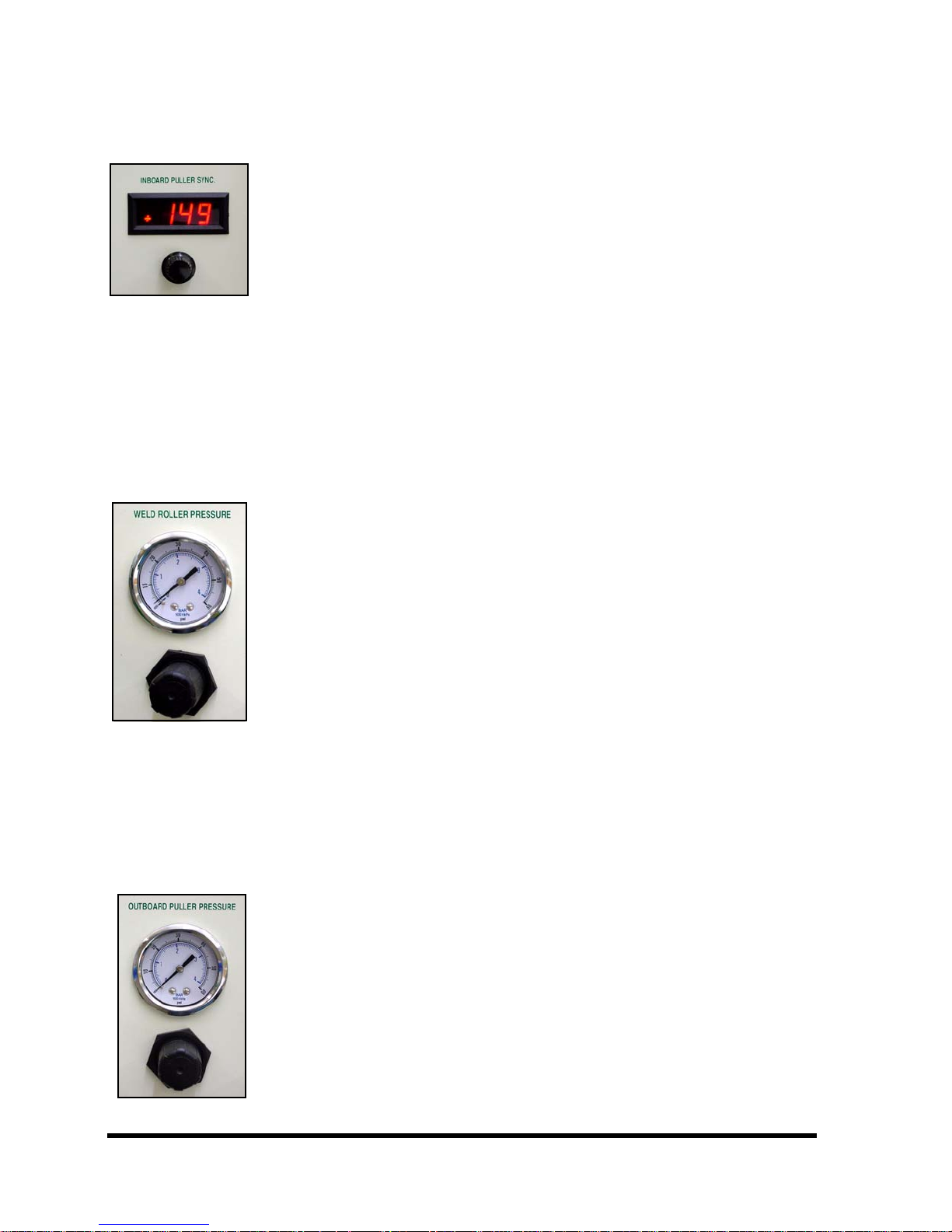
Figure 1.23: By turning the Outboard Puller Sync Control dial
Inboard Puller Sync
counterclockwise, the Outboard puller will decrease in speed in
relation to the weld rollers.
The Master Speed Control for the machine determines the overall
speed of the weld rollers and puller rollers. The speed ratio between
the weld rollers and puller rollers will remain the same whether
increasing or decreasing the Master Speed Control.
Inboard Puller Sync
The purpose of the Inboard Puller Sync Control is to synchronize
the inboard puller rollers with the weld rollers. The Inboard Puller
Figure 1.24: By turning the Inboard Puller Sync Control dial clockwise, the
Weld Roller
Pressure
Sync numbers are only used as a reference and do not have any
relationship and should not match the Master Speed Control settings.
Inboard Puller will increase in speed in relation to the weld rollers.
By running the Inboard Puller Sync Control dial counterclockwise,
the Inboard Puller will decrease in speed in relation to the weld
rollers.
The Master Speed Control for the machine determines the overall
speed of the weld rollers and puller rollers. The speed ratio between
the weld rollers and puller rollers will remain the same whether
increasing or decreasing the Master Speed Control.
Weld Roller Pressure
The purpose of the Weld Roller Pressure Regulator is to vary the
amount of pneumatic pressure between the weld rollers.
By turning the Weld Roller Pressure Regulator clockwise, the
pressure between the weld rollers will increase.
Figure 1.25: By turning the Weld Roller Pressure Regulator counterclockwise,
Outboard Puller
Pressure
the pressure between the weld rollers will decrease.
Outboard Puller Pressure
The purpose of the Outboard Puller Pressure Regulator is to vary
the amount of pneumatic pressure on the outboard puller rollers.
By turning the Outboard Puller Pressure Regulator clockwise, the
pressure of the Outboard Puller will increase.
By turning the Outboard Puller Pressure Regulator
counterclockwise, the pressure of the Outboard Puller will decrease.
Chapter 1: Machine Overview | Section 1.6: Controls: Purposes and Functions
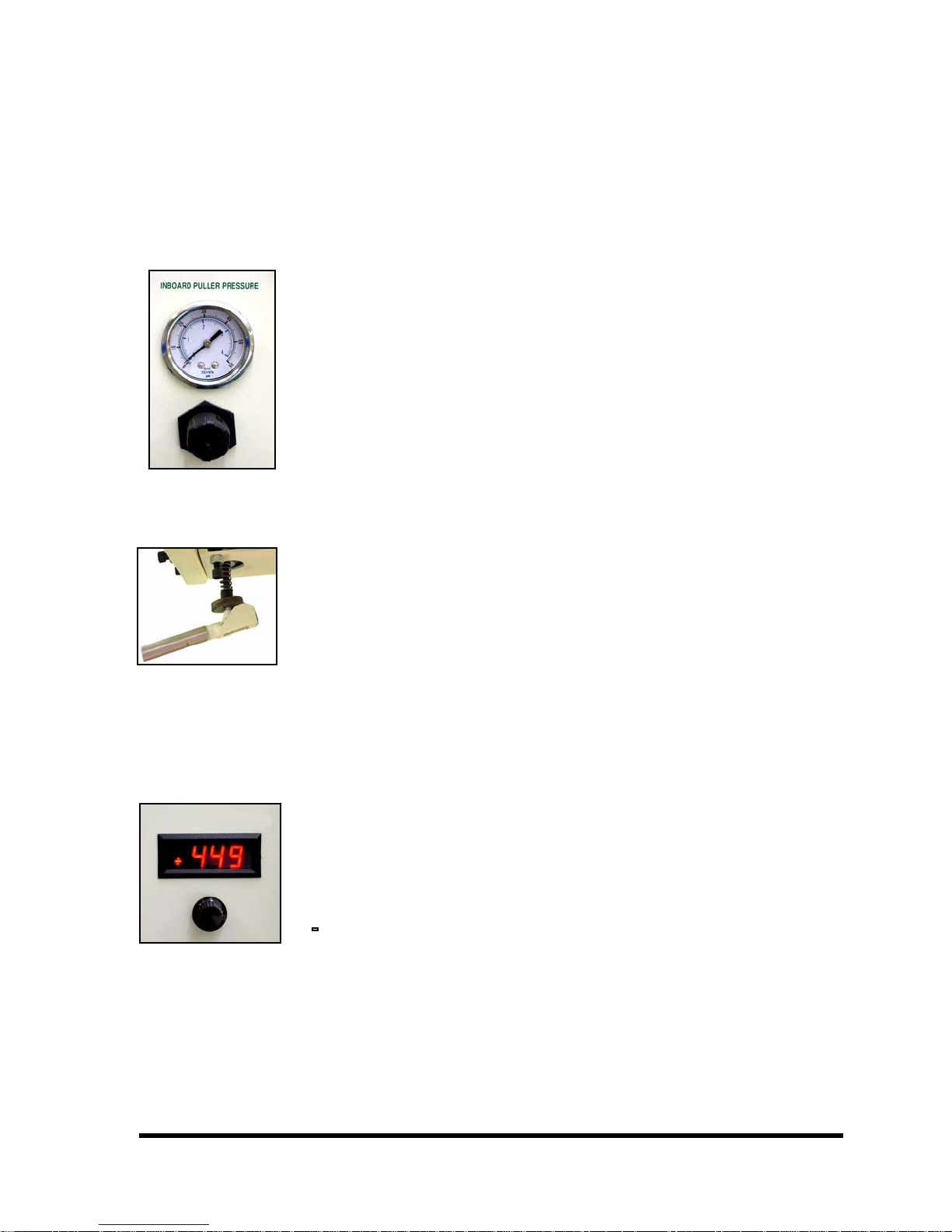
Figure 1.26: Inboard Puller Pressure
Inboard Puller
Pressure
NOTE: Whenever decreasing the pressure you need to drop the
pressure to 0 psi then move to your desired pressure, which is usually
30 psi.
The purpose of the Inboard Puller Pressure Regulator is to vary
the amount of pneumatic pressure on the inboard puller rollers.
By turning the Inboard Puller Pressure Regulator clockwise, the
pressure of the Outboard Puller will increase.
By turning the Inboard Puller Pressure Regulator
counterclockwise, the pressure of the Outboard Puller will decrease.
Page 1-13
Figure 1.27:
Rear Roller
Rear Roller Tensioner
T e n s i o n e r
NOTE: Whenever decreasing the pressure you need to drop the
pressure to 0 psi then move to your desired pressure, which is usually
30 psi.
The purpose of the Rear Roller Tensioner is to stretch material
that shrinks due to the heat from the welding process, in conjunction
with the double roller welding arm. Engaging the Rear Roller
Te nsi on er L eve r to t he ve rt ic al po sition will apply pressure between
the two rear rollers.
By turning the Rear Roller Tensioner Lever clockwise, the
pressure between the Rear Rollers will increase, causing more stretch
in the material.
Figure 1.28: By turning the Rear Roller Tensioner Lever counterclockwise, the
Upper Weld Roller
Sync
pressure between the Rear Rollers will decrease, causing less stretch
in the material.
Upper Weld Roller Sync/Vari-Drive
Every Miller Weldmaster T-500 and T-100 comes with some type of
Upper Weld Roller Sync Control. It may have a digital Upper Weld
Roller Sync Control, or it will have a mechanical Vari-Drive Control.
Drive is to vary the synchronization between the upper and lower
weld rollers.
upper weld roller speed will increase in relation to the lower weld
roller.
Chapter 1: Machine Overview | Section 1.6: Controls: Purposes and Functions
The purpose of the Upper Weld Roller Sync Control and the Vari-
By increasing the Upper Weld Roller Sync or the Vari-Drive, the
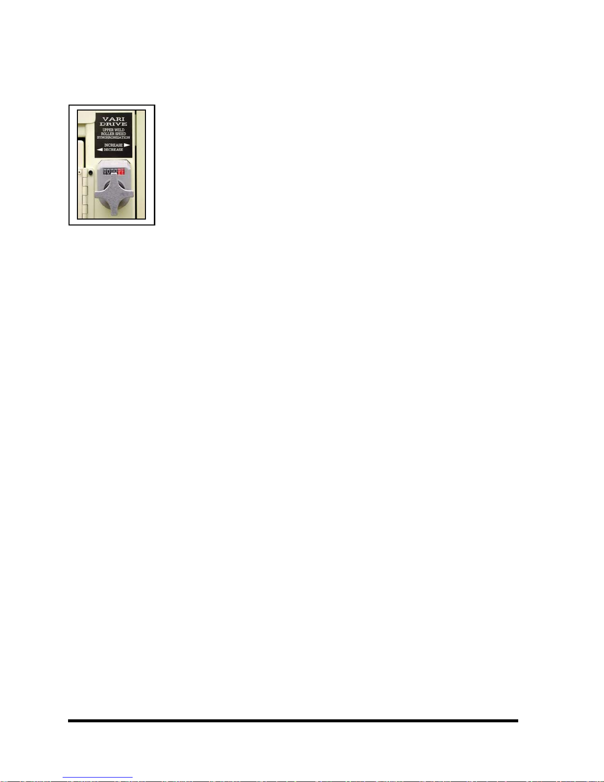
Page 1-14
Figure 1.29: By decreasing the Upper Weld Roller Sync or the Vari-Drive, the
Vari-Drive
upper weld roller speed will decrease in relation to the lower weld
roller.
Chapter 1: Machine Overview | Section 1.6: Controls: Purposes and Functions

Page 2-1
Chapter 2: Heating System Overview and
Adjustments
Section 2.1: Hot Air Heating System
Nozzle placement is a key component in heat sealing. A properly placed nozzle will be
centered on the weld rollers approximately 1/4 - 1/2 inches away and have a slight whistle
during the welding process.
WA RN I NG ! The Hot Air Heating System near the Nozzle and the Nozzle Clamp is very
hot and will cause burning if not allowed to cool before handling. Turn the
Heat and Power Switches to the off position and allow the Hot Air Heating
System to cool for at least 30 minutes before touching with bare skin.
Length of time may vary depending on ambient temperature and
environmental conditions.
Adjusting Nozzle
When an adjustment is needed, set the desired Weld Roller pressure (or P.S.I.) and turn
the Speed Control to the lowest setting. Make the adjustment, and then check the Nozzle
placement by engaging the Drive Foot Switch.
The angle of the Nozzle must be adjusted after the machine has cooled down to avoid
personal injury. While all other Nozzle adjustments must be made after the machine has
been brought up to welding temperature.
The Weld Roller Pressure and the temperature of the Nozzle both play an important
role in the placement of the Nozzle. Varying Weld Roller Pressure (or P.S.I.) will change the
position of the Weld Roller Pinch Point causing the Nozzle to become misaligned. The
Nozzle placement will also change when welding at different temperatures. As the
temperature increases, the Nozzle expands lowering it’s position on the Weld Rollers. As
the Temperature decreases, the Nozzle contracts raising it’s position on the Weld Rollers.
Check the placement of the Nozzle when the temperature is changed more than 200
degrees F (93 degrees C) or the Weld Roller Pressure is changed more than 10 p.s.i.
NOTE: Every 200° F change in temperature will require realignment of Nozzle.
Chapter 2: Heating System Overview and Adjustments | Section 2.1: Hot Air Heating System
Page 2-2
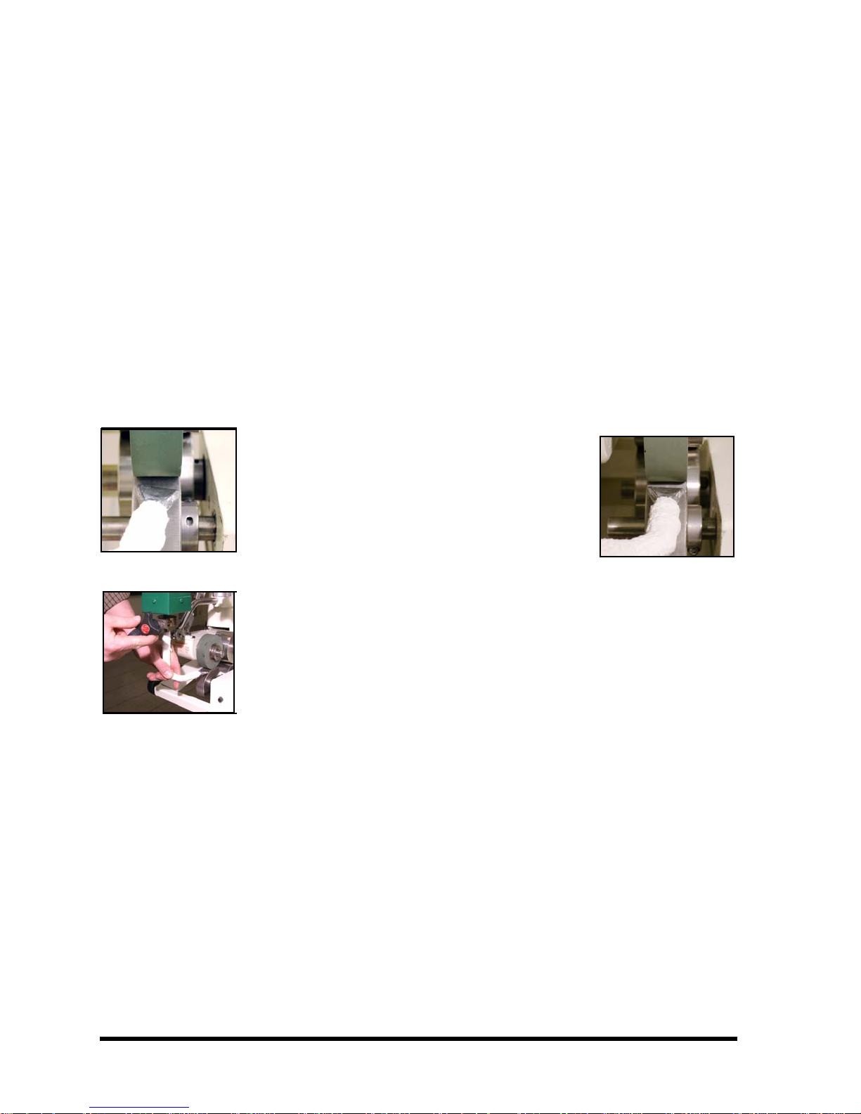
Adjusting Nozzle Angle
The Nozzle angle is the angle at which the Nozzle Tip is blowing air in at the Weld
Rollers. This relationship should be parallel so that air flow is directed into the Weld Roller
Pinch Point. Having the angle of the Nozzle misaligned will cause the fabric to become
overheated leaving the seam under heated and unwelded. Before proceeding with
adjusting the angle you must be certain that the temperature of the Nozzle is cool to the
touch. Turn the Heat Switch to the off position and wait for the machine to cool down.
Depress the Drive Foot Switch to swing Nozzle into place and check angle of the Nozzle. If
not properly placed, (Figure2.1) release the Drive Foot Switch to swing Nozzle out and
proceed with the following:
The angle of the Nozzle must be adjusted after the machine has cooled down to avoid
personal injury.
Figure 2.1:
Figure 2.2:
1. Turn the Override Switch to the on position
which will swing the Nozzle into place so
that the angle can be adjusted.
2. Loosen the Nozzle Clamp enough to let the
Nozzle rotate but not become
disconnected. (Figure2.2)
3. Rotate the Nozzle accordingly so that the
angle of the Nozzle Tip is parallel with the
Weld Rollers
4. Tighten the Nozzle Clamp so that the
Nozzle is held securely in place forming a
tight seal around the ball end of the Nozzle
and the Dual Element Housing. (Figure2.2)
Check to see if the proper adjustment of
the Nozzle has been made. (Figure2.3)
Repeat steps 1 through 4 until correct.
Figure 2.3:
Chapter 2: Heating System Overview and Adjustments | Section 2.1: Hot Air Heating System
 Loading...