

Page 1
OM-196 188K
July 2003
Processes
MIG (GMAW) Welding
Pulsed MIG (GMAW-P)
Flux Cored (FCAW) W elding
Automatic Welding
Description
Automatic Welding Interface And
Arc Welding Power Source
Operating Instructions and
Programming Instructions for
Auto Invision II
Visit our website at
www.MillerWelds.com
Page 2

From Miller to You
Thank you and congratulations on choosing Miller. Now you can get
the job done and get it done right. We know you don’t have time to do
it any other way.
That’s why when Niels Miller first started building arc welders in 1929,
he made sure his products offered long-lasting value and superior
quality. Like you, his customers couldn’t afford anything less. Miller
products had to be more than the best they could be. They had to be the
best you could buy.
Today, the people that build and sell Miller products continue the
tradition. They’re just as committed to providing equipment and service
that meets the high standards of quality and value established in 1929.
This Owner’s Manual is designed to help you get the most out of your
Miller products. Please take time to read the Safety precautions. They
will help you protect yourself against potential hazards on the worksite.
We’ve made installation and operation quick
and easy. With Miller you can count on years
of reliable service with proper maintenance.
And if for some reason the unit needs repair,
there’s a Troubleshooting section that will
help you figure out what the problem is. The
Miller is the first welding
equipment manufacturer in
the U.S.A. to be registered to
the ISO 9001:2000 Quality
System Standard.
parts list will then help you to decide the
exact part you may need to fix the problem.
Warranty and service information for your
particular model are also provided.
Working as hard as you do
– every power source from
Miller is backed by the most
hassle-free warranty in the
business.
Miller Electric manufactures a full line
of welders and welding related equipment.
For information on other quality Miller
products, contact your local Miller distributor to receive the latest full
line catalog or individual catalog sheets. To locate your nearest
distributor or service agency call 1-800-4-A-Miller, or visit us at
www.MillerWelds.com on the web.
Miller offers a Technical
Manual which provides
more detailed service and
parts information for your
unit. T o obtain a Technical
Manual, contact your local
distributor. Your distributor
can also supply you with
Welding Process Manuals
such as SMAW, GTAW,
GMAW, and GMA W-P.
Page 3

WARNING
This product, when used
for welding or cutting,
produces fumes or
gases which contain
chemicals known to the
State of California to
cause birth defects and,
in some cases, cancer.
(California Health &
Safety Code Section
25249.5 et seq.)
TABLE OF CONTENTS
SECTION 1 – SAFETY PRECAUTIONS - READ BEFORE USING 1. . . . . . . . . . . . . . . . . . . . . . . . . . . .
1-1. Symbol Usage 1. . . . . . . . . . . . . . . . . . . . . . . . . . . . . . . . . . . . . . . . . . . . . . . . . . . . . . . . . . . . . . . .
1-2. Arc Welding Hazards 1. . . . . . . . . . . . . . . . . . . . . . . . . . . . . . . . . . . . . . . . . . . . . . . . . . . . . . . . . .
1-3. Additional Symbols For Installation, Operation, And Maintenance 3. . . . . . . . . . . . . . . . . . . . .
1-4. Principal Safety Standards 3. . . . . . . . . . . . . . . . . . . . . . . . . . . . . . . . . . . . . . . . . . . . . . . . . . . . . .
1-5. EMF Information 4. . . . . . . . . . . . . . . . . . . . . . . . . . . . . . . . . . . . . . . . . . . . . . . . . . . . . . . . . . . . . .
SECTION 1 – CONSIGNES DE SECURITE – LIRE AVANT UTILISATION 5. . . . . . . . . . . . . . . . . . . . .
1-1. Signification des symboles 5. . . . . . . . . . . . . . . . . . . . . . . . . . . . . . . . . . . . . . . . . . . . . . . . . . . . . .
1-2. Dangers relatifs au soudage à l’arc 5. . . . . . . . . . . . . . . . . . . . . . . . . . . . . . . . . . . . . . . . . . . . . . .
1-3. Dangers supplémentaires en relation avec l’installation, le fonctionnement
et la maintenance 7. . . . . . . . . . . . . . . . . . . . . . . . . . . . . . . . . . . . . . . . . . . . . . . . . . . . . . . . . . . . . .
1-4. Principales normes de sécurité 8. . . . . . . . . . . . . . . . . . . . . . . . . . . . . . . . . . . . . . . . . . . . . . . . . .
1-5. Information sur les champs électromagnétiques 8. . . . . . . . . . . . . . . . . . . . . . . . . . . . . . . . . . . .
SECTION 2 – DEFINITIONS 9. . . . . . . . . . . . . . . . . . . . . . . . . . . . . . . . . . . . . . . . . . . . . . . . . . . . . . . . . . . .
2-1. Manufacturer’s Warning Label Definitions 9. . . . . . . . . . . . . . . . . . . . . . . . . . . . . . . . . . . . . . . . .
2-2. Symbols And Definitions 11. . . . . . . . . . . . . . . . . . . . . . . . . . . . . . . . . . . . . . . . . . . . . . . . . . . . . . .
2-3. Manufacturer’s Rating Label 11. . . . . . . . . . . . . . . . . . . . . . . . . . . . . . . . . . . . . . . . . . . . . . . . . . . .
2-4. Harmonic Data 11. . . . . . . . . . . . . . . . . . . . . . . . . . . . . . . . . . . . . . . . . . . . . . . . . . . . . . . . . . . . . . .
SECTION 3 – INSTALLATION 12. . . . . . . . . . . . . . . . . . . . . . . . . . . . . . . . . . . . . . . . . . . . . . . . . . . . . . . . . . .
3-1. Specifications 12. . . . . . . . . . . . . . . . . . . . . . . . . . . . . . . . . . . . . . . . . . . . . . . . . . . . . . . . . . . . . . . .
3-2. Dimensions And Weight 12. . . . . . . . . . . . . . . . . . . . . . . . . . . . . . . . . . . . . . . . . . . . . . . . . . . . . . . .
3-3. Selecting A Location 13. . . . . . . . . . . . . . . . . . . . . . . . . . . . . . . . . . . . . . . . . . . . . . . . . . . . . . . . . . .
3-4. Connection Diagram 13. . . . . . . . . . . . . . . . . . . . . . . . . . . . . . . . . . . . . . . . . . . . . . . . . . . . . . . . . . .
3-5. Weld Output Terminals And Selecting Cable Sizes 14. . . . . . . . . . . . . . . . . . . . . . . . . . . . . . . . . .
3-6. 115 Volts AC Duplex Receptacle And Circuit Breakers 14. . . . . . . . . . . . . . . . . . . . . . . . . . . . . .
3-7. Electrical Service Guide 15. . . . . . . . . . . . . . . . . . . . . . . . . . . . . . . . . . . . . . . . . . . . . . . . . . . . . . . .
3-8. Connecting Input Power 15. . . . . . . . . . . . . . . . . . . . . . . . . . . . . . . . . . . . . . . . . . . . . . . . . . . . . . . .
3-9. Rear Panel Connections 16. . . . . . . . . . . . . . . . . . . . . . . . . . . . . . . . . . . . . . . . . . . . . . . . . . . . . . .
3-10. Peripheral Receptacle Functions 17. . . . . . . . . . . . . . . . . . . . . . . . . . . . . . . . . . . . . . . . . . . . . . . .
3-11. Touch Sensor Operation 18. . . . . . . . . . . . . . . . . . . . . . . . . . . . . . . . . . . . . . . . . . . . . . . . . . . . . . . .
3-12. Touch Sensor Board PC18 Switch S1 Settings 18. . . . . . . . . . . . . . . . . . . . . . . . . . . . . . . . . . . . .
3-13. Connecting Setup Pendant To Welding Power Source 19. . . . . . . . . . . . . . . . . . . . . . . . . . . . . . .
SECTION 4 – OPERATION 20. . . . . . . . . . . . . . . . . . . . . . . . . . . . . . . . . . . . . . . . . . . . . . . . . . . . . . . . . . . . .
4-1. Operational Terms 20. . . . . . . . . . . . . . . . . . . . . . . . . . . . . . . . . . . . . . . . . . . . . . . . . . . . . . . . . . . . .
4-2. Lower Front Panel Controls 21. . . . . . . . . . . . . . . . . . . . . . . . . . . . . . . . . . . . . . . . . . . . . . . . . . . . .
4-3. Meter Functions 21. . . . . . . . . . . . . . . . . . . . . . . . . . . . . . . . . . . . . . . . . . . . . . . . . . . . . . . . . . . . . .
4-4. Upper Front Panel Controls 22. . . . . . . . . . . . . . . . . . . . . . . . . . . . . . . . . . . . . . . . . . . . . . . . . . . . .
4-5. Duty Cycle And Overheating 23. . . . . . . . . . . . . . . . . . . . . . . . . . . . . . . . . . . . . . . . . . . . . . . . . . . .
4-6. Volt-Ampere Curves 23. . . . . . . . . . . . . . . . . . . . . . . . . . . . . . . . . . . . . . . . . . . . . . . . . . . . . . . . . . .
4-7. Setup Pendant Controls 24. . . . . . . . . . . . . . . . . . . . . . . . . . . . . . . . . . . . . . . . . . . . . . . . . . . . . . . .
SECTION 5 – MAINTENANCE & TROUBLESHOOTING 25. . . . . . . . . . . . . . . . . . . . . . . . . . . . . . . . . . . .
5-1. Routine Maintenance 25. . . . . . . . . . . . . . . . . . . . . . . . . . . . . . . . . . . . . . . . . . . . . . . . . . . . . . . . . .
5-2. Blowing Out Inside Of Unit 25. . . . . . . . . . . . . . . . . . . . . . . . . . . . . . . . . . . . . . . . . . . . . . . . . . . . . .
5-3. Removing Case and Measuring Input Capacitor Voltage 26. . . . . . . . . . . . . . . . . . . . . . . . . . . . .
5-4. Voltmeter/Ammeter Help Displays 27. . . . . . . . . . . . . . . . . . . . . . . . . . . . . . . . . . . . . . . . . . . . . . . .
5-5. Front Panel Error Displays 28. . . . . . . . . . . . . . . . . . . . . . . . . . . . . . . . . . . . . . . . . . . . . . . . . . . . . .
5-6. Weld Interface Board PC12 Diagnostic LED’s 29. . . . . . . . . . . . . . . . . . . . . . . . . . . . . . . . . . . . . .
5-7. Diagnostic LED’s On Weld Interface Board PC12 30. . . . . . . . . . . . . . . . . . . . . . . . . . . . . . . . . . .
5-8. Customer Interface Board PC14 Diagnostic LED’s 31. . . . . . . . . . . . . . . . . . . . . . . . . . . . . . . . . .
5-9. Diagnostic LED’s On Customer Interface Board PC14 32. . . . . . . . . . . . . . . . . . . . . . . . . . . . . . .
5-10. Motor Board PC13 Diagnostic LED’s 33. . . . . . . . . . . . . . . . . . . . . . . . . . . . . . . . . . . . . . . . . . . . .
5-11. Diagnostic LED’s On Motor Board PC13 34. . . . . . . . . . . . . . . . . . . . . . . . . . . . . . . . . . . . . . . . . .
5-12. Troubleshooting 34. . . . . . . . . . . . . . . . . . . . . . . . . . . . . . . . . . . . . . . . . . . . . . . . . . . . . . . . . . . . . . .
SECTION 6 – ELECTRICAL DIAGRAMS 36. . . . . . . . . . . . . . . . . . . . . . . . . . . . . . . . . . . . . . . . . . . . . . . . .
SECTION 7 – PARTS LIST 70. . . . . . . . . . . . . . . . . . . . . . . . . . . . . . . . . . . . . . . . . . . . . . . . . . . . . . . . . . . . . .
(continued)
Page 4

TABLE OF CONTENTS
SECTION 8 – INTRODUCTION TO PROGRAMMING 76. . . . . . . . . . . . . . . . . . . . . . . . . . . . . . . . . . . . . . .
8-1. Pulse MIG Programs 76. . . . . . . . . . . . . . . . . . . . . . . . . . . . . . . . . . . . . . . . . . . . . . . . . . . . . . . . . .
8-2. Standard Pulse Welding Programs 76. . . . . . . . . . . . . . . . . . . . . . . . . . . . . . . . . . . . . . . . . . . . . . .
8-3. Program 1 – 1.2 mm Steel (.045”), 98-2 Argon-Oxy 77. . . . . . . . . . . . . . . . . . . . . . . . . . . . . . . . .
8-4. Program 2 – 1.0 mm Steel (.040”), 80-20 Argon-CO2 77. . . . . . . . . . . . . . . . . . . . . . . . . . . . . . . .
8-5. Program 3 – 1.2 mm Steel (.045”), 80-20 Argon-CO2 78. . . . . . . . . . . . . . . . . . . . . . . . . . . . . . . .
8-6. Program 4 – .8 mm 316 (.030”), 98-2 Argon-CO2 78. . . . . . . . . . . . . . . . . . . . . . . . . . . . . . . . . . .
8-7. Program 5 – 1.0 mm 316 (.040”), 98-2 Argon-CO2 79. . . . . . . . . . . . . . . . . . . . . . . . . . . . . . . . . .
8-8. Program 6 – 1.2 mm 316 (.045”), 98-2 Argon-CO2 79. . . . . . . . . . . . . . . . . . . . . . . . . . . . . . . . . .
8-9. Program 7 – 1.0 mm 308L (.040”), 98-2 Argon-CO2 80. . . . . . . . . . . . . . . . . . . . . . . . . . . . . . . . .
8-10. Program 8 – 1.2 mm 308L (.045”), 98-2 Argon-CO2 80. . . . . . . . . . . . . . . . . . . . . . . . . . . . . . . . .
8-11. Program 1 – 1.2 mm Metal Core (.045”), 95-5 Argon-CO2 81. . . . . . . . . . . . . . . . . . . . . . . . . . . .
8-12. Program 2 – 1.4 mm Metal Core (.052”), 95-5 Argon-CO2 81. . . . . . . . . . . . . . . . . . . . . . . . . . . .
8-13. Program 3 – 1.2 mm ER 4043 (.045”), Argon 82. . . . . . . . . . . . . . . . . . . . . . . . . . . . . . . . . . . . . .
8-14. Program 4 – 1.0 mm ER 4043 (.040”), Argon 82. . . . . . . . . . . . . . . . . . . . . . . . . . . . . . . . . . . . . .
8-15. Program 5 – 1.0 mm 5356 (.040”), Argon 83. . . . . . . . . . . . . . . . . . . . . . . . . . . . . . . . . . . . . . . . . .
8-16. Program 6 – 1.2 mm ER 5356 (.045”), Argon 83. . . . . . . . . . . . . . . . . . . . . . . . . . . . . . . . . . . . . .
8-17. Program 7 – .8 mm Steel (.030”), 98-2 Argon-Oxy 84. . . . . . . . . . . . . . . . . . . . . . . . . . . . . . . . . .
8-18. Program 8 – 1.0 mm Steel (.040”), 98-2 Argon-Oxy 84. . . . . . . . . . . . . . . . . . . . . . . . . . . . . . . . .
8-19. Setup Pendant Mode Select Button 85. . . . . . . . . . . . . . . . . . . . . . . . . . . . . . . . . . . . . . . . . . . . . .
8-20. Setup Pendant Parameter Select Button 86. . . . . . . . . . . . . . . . . . . . . . . . . . . . . . . . . . . . . . . . . .
8-21. Setup Pendant Parameter Increase And Decrease Buttons 87. . . . . . . . . . . . . . . . . . . . . . . . . .
SECTION 9 – GETTING STARTED FOR PULSE WELDING 88. . . . . . . . . . . . . . . . . . . . . . . . . . . . . . . . .
9-1. Weld Cycle For Pulse Welding 88. . . . . . . . . . . . . . . . . . . . . . . . . . . . . . . . . . . . . . . . . . . . . . . . . .
9-2. Setting Preflow Sequence Display 88. . . . . . . . . . . . . . . . . . . . . . . . . . . . . . . . . . . . . . . . . . . . . . .
9-3. Setting Weld Sequence Display 89. . . . . . . . . . . . . . . . . . . . . . . . . . . . . . . . . . . . . . . . . . . . . . . . .
9-4. Setting Crater Sequence Display 89. . . . . . . . . . . . . . . . . . . . . . . . . . . . . . . . . . . . . . . . . . . . . . . .
9-5. Setting Postflow Sequence Display 90. . . . . . . . . . . . . . . . . . . . . . . . . . . . . . . . . . . . . . . . . . . . . .
SECTION 10 – TEACHING A PULSE WELDING PROGRAM 90. . . . . . . . . . . . . . . . . . . . . . . . . . . . . . . .
10-1. Pulse Waveform Explained 90. . . . . . . . . . . . . . . . . . . . . . . . . . . . . . . . . . . . . . . . . . . . . . . . . . . . .
10-2. Teach Points Explained 91. . . . . . . . . . . . . . . . . . . . . . . . . . . . . . . . . . . . . . . . . . . . . . . . . . . . . . . .
10-3. Selecting Teach Point Wire Feed Speed For Pulse Welding Program 92. . . . . . . . . . . . . . . . . .
10-4. Setting Teach Point Parameters For Pulse Welding Program 93. . . . . . . . . . . . . . . . . . . . . . . . .
10-5. Changing To Adaptive Pulse Welding 95. . . . . . . . . . . . . . . . . . . . . . . . . . . . . . . . . . . . . . . . . . . . .
SECTION 11 – TEACHING A MIG WELDING PROGRAM 95. . . . . . . . . . . . . . . . . . . . . . . . . . . . . . . . . . .
11-1. Weld Cycle For Mig Welding 95. . . . . . . . . . . . . . . . . . . . . . . . . . . . . . . . . . . . . . . . . . . . . . . . . . . .
11-2. Changing To Mig Welding 96. . . . . . . . . . . . . . . . . . . . . . . . . . . . . . . . . . . . . . . . . . . . . . . . . . . . . . .
11-3. Setting Preflow Sequence Display 96. . . . . . . . . . . . . . . . . . . . . . . . . . . . . . . . . . . . . . . . . . . . . . .
11-4. Setting Start Sequence Display 97. . . . . . . . . . . . . . . . . . . . . . . . . . . . . . . . . . . . . . . . . . . . . . . . . .
11-5. Setting Weld Sequence Display 97. . . . . . . . . . . . . . . . . . . . . . . . . . . . . . . . . . . . . . . . . . . . . . . . .
11-6. Setting Crater Sequence Display 98. . . . . . . . . . . . . . . . . . . . . . . . . . . . . . . . . . . . . . . . . . . . . . . .
11-7. Setting Retract Sequence Display 98. . . . . . . . . . . . . . . . . . . . . . . . . . . . . . . . . . . . . . . . . . . . . . .
11-8. Setting Postflow Sequence Display 99. . . . . . . . . . . . . . . . . . . . . . . . . . . . . . . . . . . . . . . . . . . . . .
11-9. Setting Run-in Sequence Display 99. . . . . . . . . . . . . . . . . . . . . . . . . . . . . . . . . . . . . . . . . . . . . . . .
SECTION 12 – SETTING SharpArcE CONTROL 100. . . . . . . . . . . . . . . . . . . . . . . . . . . . . . . . . . . . . . . . . . .
12-1. Selecting And Adjusting SharpArcE Control 100. . . . . . . . . . . . . . . . . . . . . . . . . . . . . . . . . . . . . . .
SECTION 13 – USING THE OPTIONAL DATA CARD 101. . . . . . . . . . . . . . . . . . . . . . . . . . . . . . . . . . . . . . .
13-1. Installing Data Card 101. . . . . . . . . . . . . . . . . . . . . . . . . . . . . . . . . . . . . . . . . . . . . . . . . . . . . . . . . . .
13-2. Using The Data Card 102. . . . . . . . . . . . . . . . . . . . . . . . . . . . . . . . . . . . . . . . . . . . . . . . . . . . . . . . . .
13-3. Naming Programs And Writing To Card 103. . . . . . . . . . . . . . . . . . . . . . . . . . . . . . . . . . . . . . . . . . .
13-4. Reading From Card 104. . . . . . . . . . . . . . . . . . . . . . . . . . . . . . . . . . . . . . . . . . . . . . . . . . . . . . . . . . .
13-5. Reading (Or Deleting) From An Empty Card 105. . . . . . . . . . . . . . . . . . . . . . . . . . . . . . . . . . . . . . .
13-6. Deleting Programs From Card 105. . . . . . . . . . . . . . . . . . . . . . . . . . . . . . . . . . . . . . . . . . . . . . . . . . .
13-7. Selecting Security Lock 106. . . . . . . . . . . . . . . . . . . . . . . . . . . . . . . . . . . . . . . . . . . . . . . . . . . . . . . .
(continued)
Page 5

TABLE OF CONTENTS
SECTION 14 – SETUP 107. . . . . . . . . . . . . . . . . . . . . . . . . . . . . . . . . . . . . . . . . . . . . . . . . . . . . . . . . . . . . . . . .
14-1. Setup Flow Chart 107. . . . . . . . . . . . . . . . . . . . . . . . . . . . . . . . . . . . . . . . . . . . . . . . . . . . . . . . . . . . .
14-2. Using Setup Di s p l a y s 108. . . . . . . . . . . . . . . . . . . . . . . . . . . . . . . . . . . . . . . . . . . . . . . . . . . . . . . . . .
14-3. Selecting Or Changing Access Code 109. . . . . . . . . . . . . . . . . . . . . . . . . . . . . . . . . . . . . . . . . . . . .
14-4. Selecting Voltage Correction 110. . . . . . . . . . . . . . . . . . . . . . . . . . . . . . . . . . . . . . . . . . . . . . . . . . . .
14-5. Selecting Auxiliary Output 110. . . . . . . . . . . . . . . . . . . . . . . . . . . . . . . . . . . . . . . . . . . . . . . . . . . . . .
14-6. Selecting Voltage Sensing Method 110. . . . . . . . . . . . . . . . . . . . . . . . . . . . . . . . . . . . . . . . . . . . . . .
14-7. Selecting Arc Start Method 111. . . . . . . . . . . . . . . . . . . . . . . . . . . . . . . . . . . . . . . . . . . . . . . . . . . . .
14-8. Resetting Arc Time 11 1. . . . . . . . . . . . . . . . . . . . . . . . . . . . . . . . . . . . . . . . . . . . . . . . . . . . . . . . . . . .
14-9. Selecting Units For Wire Feed Speed And Motor Type 112. . . . . . . . . . . . . . . . . . . . . . . . . . . . . . .
14-10. Selecting Wire Type 113. . . . . . . . . . . . . . . . . . . . . . . . . . . . . . . . . . . . . . . . . . . . . . . . . . . . . . . . . . .
14-11. Defining Display Value 113. . . . . . . . . . . . . . . . . . . . . . . . . . . . . . . . . . . . . . . . . . . . . . . . . . . . . . . . .
14-12. Resetting Memory 114. . . . . . . . . . . . . . . . . . . . . . . . . . . . . . . . . . . . . . . . . . . . . . . . . . . . . . . . . . . . .
14-13. Selecting Arc Start/Volt Sense Error Shutdown 114. . . . . . . . . . . . . . . . . . . . . . . . . . . . . . . . . . . . .
14-14. Selecting Program Name Feature 115. . . . . . . . . . . . . . . . . . . . . . . . . . . . . . . . . . . . . . . . . . . . . . . .
14-15. Remote Program Select 115. . . . . . . . . . . . . . . . . . . . . . . . . . . . . . . . . . . . . . . . . . . . . . . . . . . . . . . .
14-16. Remote Program Setting 115. . . . . . . . . . . . . . . . . . . . . . . . . . . . . . . . . . . . . . . . . . . . . . . . . . . . . . .
14-17. Jog Wire Feed Speed Selection 116. . . . . . . . . . . . . . . . . . . . . . . . . . . . . . . . . . . . . . . . . . . . . . . . .
14-18. Flow Selection 116. . . . . . . . . . . . . . . . . . . . . . . . . . . . . . . . . . . . . . . . . . . . . . . . . . . . . . . . . . . . . . . .
14-19. Arc Voltage Error Selection 117. . . . . . . . . . . . . . . . . . . . . . . . . . . . . . . . . . . . . . . . . . . . . . . . . . . . .
14-20. Stick Check Selection 117. . . . . . . . . . . . . . . . . . . . . . . . . . . . . . . . . . . . . . . . . . . . . . . . . . . . . . . . . .
14-21. Setting Ramps Function 118. . . . . . . . . . . . . . . . . . . . . . . . . . . . . . . . . . . . . . . . . . . . . . . . . . . . . . . .
14-22. Software Version Number 118. . . . . . . . . . . . . . . . . . . . . . . . . . . . . . . . . . . . . . . . . . . . . . . . . . . . . .
14-23. Exiting The Setup Menu 118. . . . . . . . . . . . . . . . . . . . . . . . . . . . . . . . . . . . . . . . . . . . . . . . . . . . . . . .
SECTION 15 – CONTROL MENU 119. . . . . . . . . . . . . . . . . . . . . . . . . . . . . . . . . . . . . . . . . . . . . . . . . . . . . . . .
15-1. Using Menu Display 119. . . . . . . . . . . . . . . . . . . . . . . . . . . . . . . . . . . . . . . . . . . . . . . . . . . . . . . . . . .
15-2. Setting Rise Time Parameter 120. . . . . . . . . . . . . . . . . . . . . . . . . . . . . . . . . . . . . . . . . . . . . . . . . . . .
15-3. Setting Adaptive Parameters 120. . . . . . . . . . . . . . . . . . . . . . . . . . . . . . . . . . . . . . . . . . . . . . . . . . . .
15-4. Setting Auto Configure Parameter 121. . . . . . . . . . . . . . . . . . . . . . . . . . . . . . . . . . . . . . . . . . . . . . . .
15-5. Setting Retract On/Off 122. . . . . . . . . . . . . . . . . . . . . . . . . . . . . . . . . . . . . . . . . . . . . . . . . . . . . . . . .
15-6. Setting Sharp Start On/Off 122. . . . . . . . . . . . . . . . . . . . . . . . . . . . . . . . . . . . . . . . . . . . . . . . . . . . . .
15-7. Exiting The Control Menu 123. . . . . . . . . . . . . . . . . . . . . . . . . . . . . . . . . . . . . . . . . . . . . . . . . . . . . . .
OPTIONS AND ACCESSORIES
WARRANTY
Page 6

Declaration of Conformity For
European Community (CE) Products
Manufacturer’s Name: Miller Electric Mfg. Co.
Manufacturer’s Address: 1635 W. Spencer Street
Appleton, WI 54914 USA
Declares that the product: Auto Invision II
conforms to the following Directives and Standards:
Directives
Electromagnetic compatibility Directives: 89/336/EEC, 92/31/EEC
Low Voltage Directive: 73/23/EEC
Machinery Directives: 89/392/EEC, 91/368/EEC, 93/C 133/04, 93/68/EEC
Standards
Electromagnetic compatibility (EMC) Product standard for arc welding equipment:
EN50199: December 1995
Arc Welding Equipment part 1: CEI IEC 60974
Degrees of Protection provided by Enclosures (IP code): IEC 529: 1989
Draft IEC 60974-5 Arc Welding Equipment part 5: wire feeders JWG1 (Sec) 158 July 2000
Insulation coordination for equipment within low-voltage systems:
Part 1: Principles, requirements and tests: IEC 664-1: 1992
European Contact: Mr. Danilo Fedolfi, Managing Director
ITW WELDING PRODUCTS ITALY S.r.l.
Via Privata Iseo 6/E
20098 San Giuliano
Milanese, Italy
dec_con1_11/02
Telephone: 39(02)982901
Fax: 39(02)98290–203
Page 7
SECTION 1 – SAFETY PRECAUTIONS - READ BEFORE USING
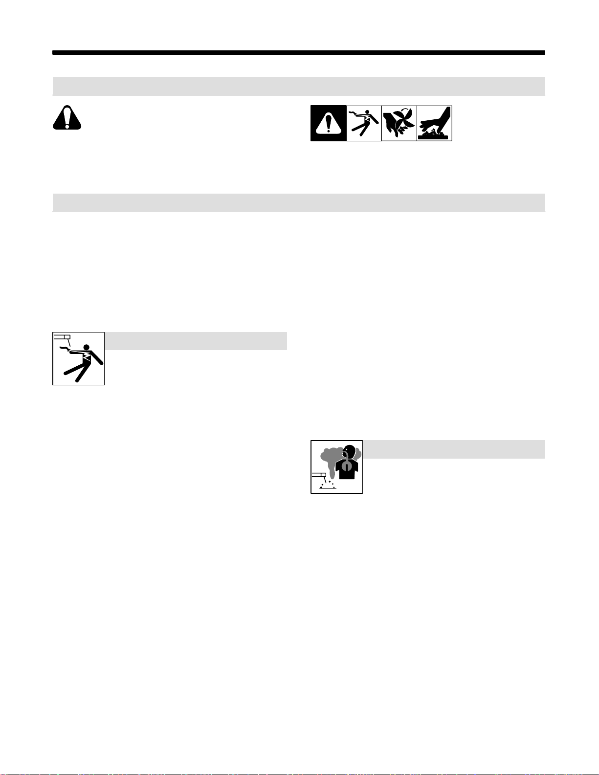
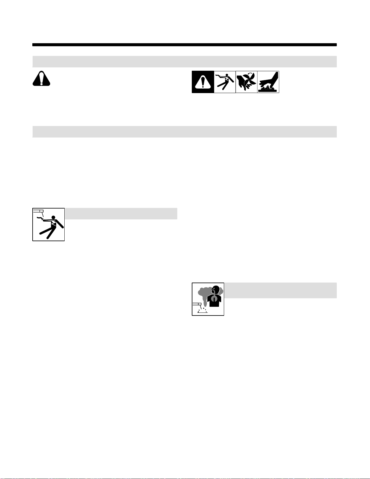
1-1. Symbol Usage
Means Warning! Watch Out! There are possible hazards
with this procedure! The possible hazards are shown in
the adjoining symbols.
som _nd_4/98
Y Marks a special safety message.
. Means “Note”; not safety related.
1-2. Arc Welding Hazards
Y The symbols shown below are used throughout this manual to
call attention to and identify possible hazards. When you see
the symbol, watch out, and follow the related instructions to
avoid the hazard. The safety information given below is only
a summary of the more complete safety information found in
the Safety Standards listed in Section 1-4. Read and follow all
Safety Standards.
Y Only qualified persons should install, operate, maintain, and
repair this unit.
Y During operation, keep everybody, especially children, away.
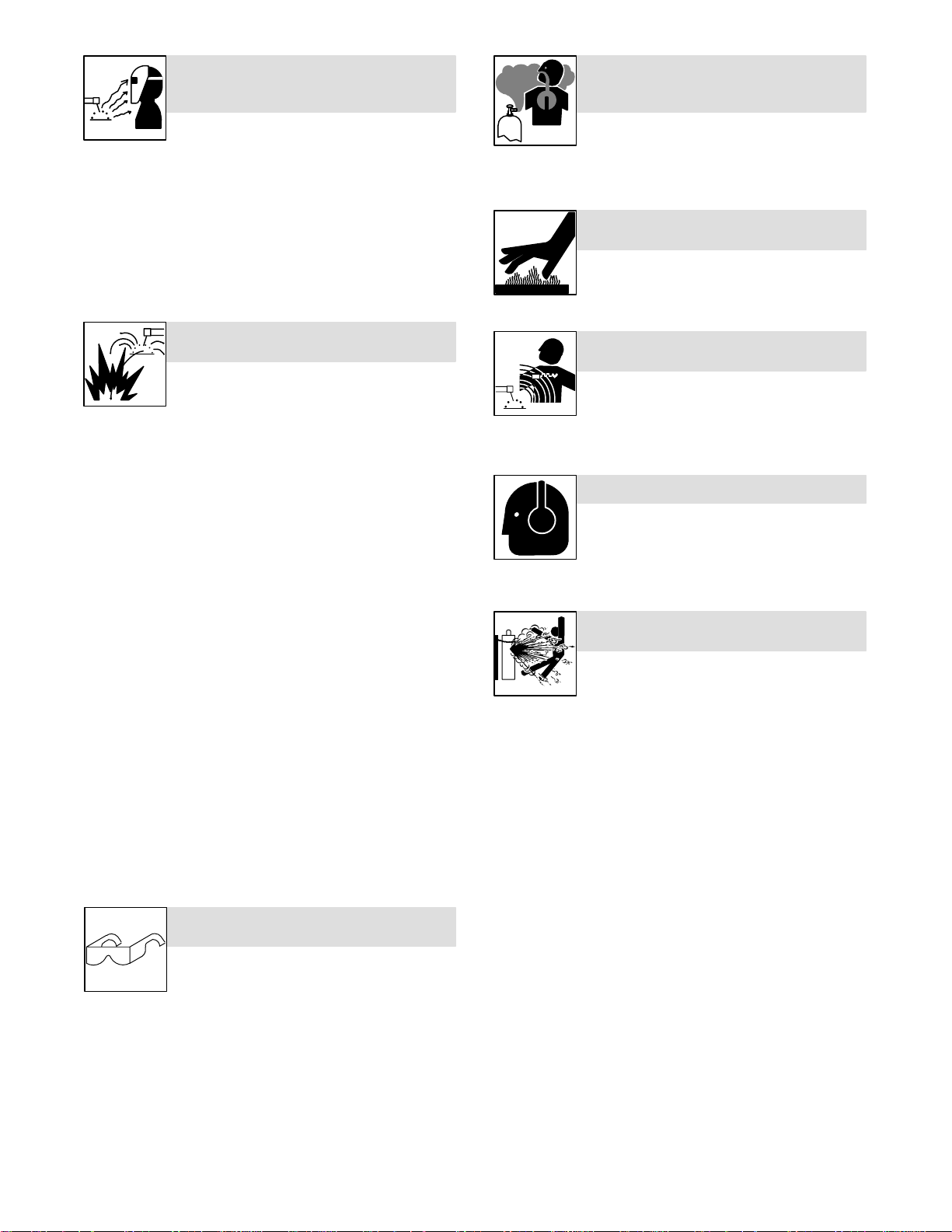
ELECTRIC SHOCK can kill.
Touching live electrical parts can cause fatal shocks
or severe burns. The electrode and work circuit is
electrically live whenever the output is on. The input
live when power is on. In semiautomatic or automatic wire welding, the
wire, wire reel, drive roll housing, and all metal parts touching the
welding wire are electrically live. Incorrectly installed or improperly
grounded equipment is a hazard.
D Do not touch live electrical parts.
D Wear dry, hole-free insulating gloves and body protection.
D Insulate yourself from work and ground using dry insulating mats
or covers big enough to prevent any physical contact with the work
or ground.
D Do not use AC output in damp areas, if movement is confined, or if
there is a danger of falling.
D Use AC output ONL Y if required for the welding process.
D If AC output is required, use remote output control if present on
unit.
D Disconnect input power or stop engine before installing or
servicing this equipment. Lockout/tagout input power according to
OSHA 29 CFR 1910.147 (see Safety Standards).
D Properly install and ground this equipment according to its
Owner’s Manual and national, state, and local codes.
D Always verify the supply ground – check and be sure that input
power cord ground wire is properly connected to ground terminal in
disconnect box or that cord plug is connected to a properly
grounded receptacle outlet.
D When making input connections, attach proper grounding conduc-
tor first – double-check connections.
D Frequently inspect input power cord for damage or bare wiring –
replace cord immediately if damaged – bare wiring can kill.
D Turn of f all equipment when not in use.
D Do not use worn, damaged, undersized, or poorly spliced cables.
D Do not drape cables over your body .
power circuit and machine internal circuits are also
This group of symbols means Warning! Watch Out! possible
ELECTRIC SHOCK, MOVING PARTS, and HOT PARTS hazards.
Consult symbols and related instructions below for necessary actions
to avoid the hazards.
D If earth grounding of the workpiece is required, ground it directly
with a separate cable.
D Do not touch electrode if you are in contact with the work, ground,
or another electrode from a different machine.
D Use only well-maintained equipment. Repair or replace damaged
parts at once. Maintain unit according to manual.
D Wear a safety harness if working above floor level.
D Keep all panels and covers securely in place.
D Clamp work cable with good metal-to-metal contact to workpiece
or worktable as near the weld as practical.
D Insulate work clamp when not connected to workpiece to prevent
contact with any metal object.
D Do not connect more than one electrode or work cable to any
single weld output terminal.
SIGNIFICANT DC VOLTAGE exists after removal of
input power on inverters.
D Turn Off inverter, disconnect input power, and discharge input
capacitors according to instructions in Maintenance Section
before touching any parts.
FUMES AND GASES can be hazardous.
Welding produces fumes and gases. Breathing
these fumes and gases can be hazardous to your
health.
D Keep your head out of the fumes. Do not breathe the fumes.
D If inside, ventilate the area and/or use exhaust at the arc to remove
welding fumes and gases.
D If ventilation is poor , use an approved air-supplied respirator.
D Read the Material Safety Data Sheets (MSDSs) and the
manufacturer’s instructions for metals, consumables, coatings,
cleaners, and degreasers.
D Work in a confined space only if it is well ventilated, or while
wearing an air-supplied respirator. Always have a trained watchperson nearby. Welding fumes and gases can displace air and
lower th e oxygen level causing injury or death. Be sure the breathing air is safe.
D Do not weld in locations near degreasing, cleaning, or spraying op-
erations. The heat and rays of the arc can react with vapors to form
highly toxic and irritating gases.
D Do not weld on coated metals, such as galvanized, lead, or
cadmium plated steel, unless the coating is removed from the weld
area, the area is well ventilated, and if necessary, while wearing an
air-supplied respirator. The coatings and any metals containing
these elements can give off toxic fumes if welded.
OM-196 188 Page 1
Page 8
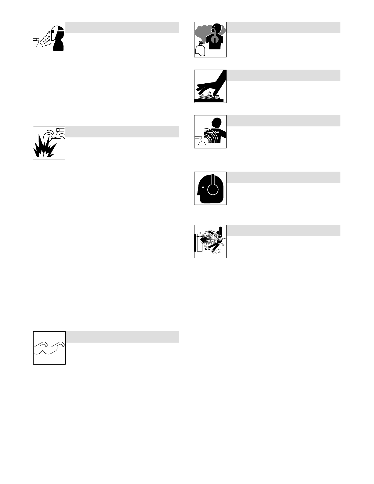
ARC RAYS can burn eyes and skin.
BUILDUP OF GAS can injure or kill.
Arc rays from the welding process produce intense
visible and invisible (ultraviolet and infrared) rays
that can burn eyes and skin. Sparks fly off from the
weld.
D Wear a welding helmet fitted with a proper shade of filter to protect
your face and eyes when welding or watching (see ANSI Z49.1
and Z87.1 listed in Safety Standards).
D Wear approved safety glasses with side shields under your
helmet.
D Use protective screens or barriers to protect others from flash and
glare; warn others not to watch the arc.
D Wear protective clothing made from durable, flame-resistant mate-
rial (leather and wool) and foot protection.
WELDING can cause fire or explosion.
Welding on closed containers, such as tanks,
drums, or pipes, can cause them to blow up. Sparks
can fly off from the welding arc. The flying sparks, hot
burns. Accidental contact of electrode to metal objects can cause
sparks, explosion, overheating, or fire. Check and be sure the area is
safe before doing any welding.
D Protect yourself and others from flying sparks and hot metal.
D Do not weld where flying sparks can strike flammable material.
D Remove all flammables within 35 ft (10.7 m) of the welding arc. If
this is not possible, tightly cover them with approved covers.
D Be alert that welding sparks and hot materials from welding can
easily go through small cracks and openings to adjacent areas.
D Watch for fire, and keep a fire extinguisher nearby.
D Be aware that welding on a ceiling, floor, bulkhead, or partition can
cause fire on the hidden side.
D Do not weld on closed containers such as tanks, drums, or pipes,
unless they are properly prepared according to AWS F4.1 (see
Safety Standards).
D Connect work cable to the work as close to the welding area as
practical to prevent welding current from traveling long, possibly
unknown paths and causing electric shock and fire hazards.
D Do not use welder to thaw frozen pipes.
D Remove stick electrode from holder or cut off welding wire at
contact tip when not in use.
D Wear oil-free protective garments such as leather gloves, heavy
shirt, cuffless trousers, high shoes, and a cap.
D Remove any combustibles, such as a butane lighter or matches,
from your person before doing any welding.
workpiece, and hot equipment can cause fires and
FLYING METAL can injure eyes.
D Welding, chipping, wire brushing, and grinding
cause sparks and flying metal. As welds cool,
they can throw off slag.
D Wear approved safety glasses with side
shields even under your welding helmet.
D Shut off shielding gas supply when not in use.
D Always ventilate confined spaces or use
approved air-supplied respirator.
HOT PARTS can cause severe burns.
D Do not touch hot parts bare handed.
D Allow cooling period before working on gun or
torch.
MAGNETIC FIELDS can affect pacemakers.
D Pacemaker wearers keep away.
D Wearers should consult their doctor before
going near arc welding, gouging, or spot
welding operations.
NOISE can damage hearing.
Noise from some processes or equipment can
damage hearing.
D Wear approved ear protection if noise level is
high.
CYLINDERS can explode if damaged.
Shielding gas cylinders contain gas under high
pressure. If damaged, a cylinder can explode. Since
gas cylinders are normally part of the welding
process, be sure to treat them carefully .
D Protect compressed gas cylinders from excessive heat, mechani-
cal shocks, slag, open flames, sparks, and arcs.
D Install cylinders in an upright position by securing to a stationary
support or cylinder rack to prevent falling or tipping.
D Keep cylinders away from any welding or other electrical circuits.
D Never drape a welding torch over a gas cylinder .
D Never allow a welding electrode to touch any cylinder .
D Never weld on a pressurized cylinder – explosion will result.
D Use only correct shielding gas cylinders, regulators, hoses, and fit-
tings designed for the specific application; maintain them and
associated parts in good condition.
D Turn face away from valve outlet when opening cylinder valve.
D Keep protective cap in place over valve except when cylinder is in
use or connected for use.
D Read and follow instructions on compressed gas cylinders,
associated equipment, and CGA publication P-1 listed in Safety
Standards.
OM-196 188 Page 2
Page 9
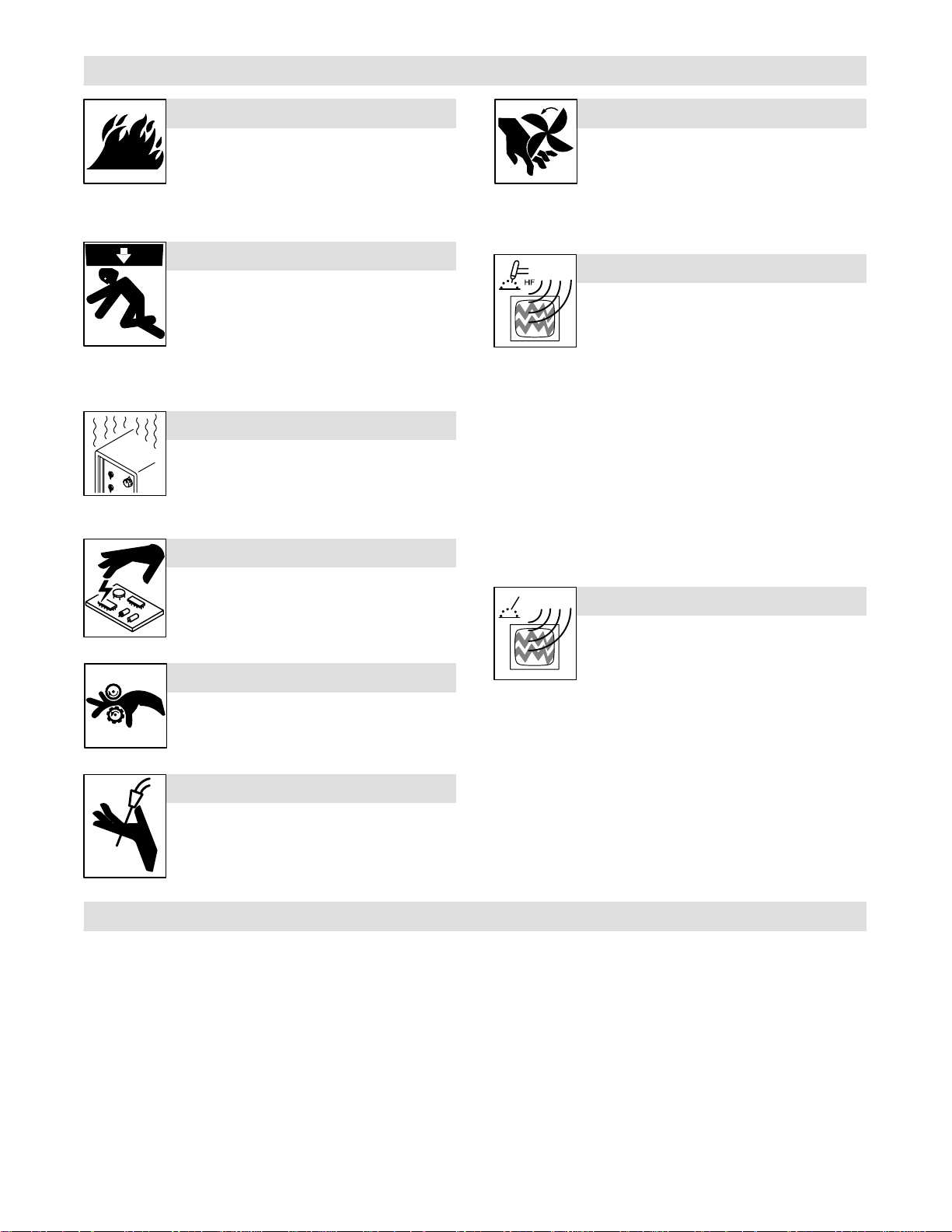
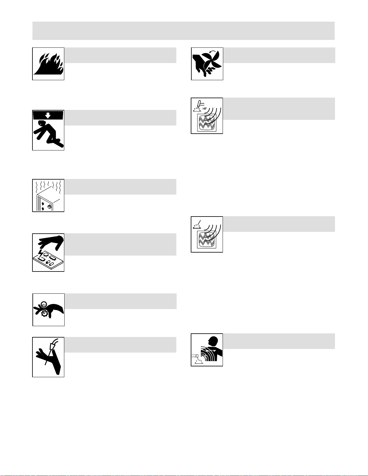
1-3. Additional Symbols For Installation, Operation, And Maintenance
FIRE OR EXPLOSION hazard.
D Do not install or place unit on, over, or near
combustible surfaces.
D Do not install unit near flammables.
D Do not overload building wiring – be sure power supply system is
properly sized, rated, and protected to handle this unit.
FALLING UNIT can cause injury.
D Use lifting eye to lift unit only, NOT running
gear, gas cylinders, or any other accessories.
D Use equipment of adequate capacity to lift and
support unit.
D If using lift forks to move unit, be sure forks are
long enough to extend beyond opposite side of
unit.
OVERUSE can cause OVERHEATING
D Allow cooling period; follow rated duty cycle.
D Reduce current or reduce duty cycle before
starting to weld again.
D Do not block or filter airflow to unit.
STATIC (ESD) can damage PC boards.
MOVING PARTS can cause injury.
D Keep away from moving parts such as fans.
D Keep all doors, panels, covers, and guards
closed and securely in place.
H.F. RADIATION can cause interference.
D High-frequency (H.F.) can interfere with radio
navigation, safety services, computers, and
communications equipment.
D Have only qualified persons familiar with
electronic equipment perform this installation.
D The user is responsible for having a qualified electrician prompt-
ly correct any interference problem resulting from the installation.
D If notified by the FCC about interference, stop using the
equipment at once.
D Have the installation regularly checked and maintained.
D Keep high-frequency source doors and panels tightly shut, keep
spark gaps at correct setting, and use grounding and shielding to
minimize the possibility of interference.
D Put on grounded wrist strap BEFORE handling
boards or parts.
D Use proper static-proof bags and boxes to
store, move, or ship PC boards.
MOVING PARTS can cause injury.
D Keep away from moving parts.
D Keep away from pinch points such as drive
rolls.
WELDING WIRE can cause injury.
D Do not press gun trigger until instructed to do
so.
D Do not point gun toward any part of the body,
other people, or any metal when threading
welding wire.
1-4. Principal Safety Standards
Safety in Welding and Cutting, ANSI Standard Z49.1, from American
Welding Society, 550 N.W. LeJeune Rd, Miami FL 33126
Safety and Health Standards, OSHA 29 CFR 1910, from Superintendent of Documents, U.S. Government Printing Office, Washington, D.C.
20402.
Recommended Safe Practices for the Preparation for Welding and Cutting of Containers That Have Held Hazardous Substances, American
Welding Society Standard AWS F4.1, from American Welding Society,
550 N.W. LeJeune Rd, Miami, FL 33126
National Electrical Code, NFPA Standard 70, from National Fire Protection Association, Batterymarch Park, Quincy, MA 02269.
ARC WELDING can cause interference.
D Electromagnetic energy can interfere with
sensitive electronic equipment such as
computers and computer-driven equipment
such as robots.
D Be sure all equipment in the welding area is
electromagnetically compatible.
D To reduce possible interference, keep weld cables as short as
possible, close together, and down low, such as on the floor.
D Locate welding operation 100 meters from any sensitive elec-
tronic equipment.
D Be sure this welding machine is installed and grounded
according t o this manual.
D If interference still occurs, the user must take extra measures
such as moving the welding machine, using shielded cables,
using line filters, or shielding the work area.
Safe Handling of Compressed Gases in Cylinders, CGA Pamphlet P-1,
from Compressed Gas Association, 1235 Jefferson Davis Highway,
Suite 501, Arlington, VA 22202.
Code for Safety in Welding and Cutting, CSA Standard W1 17.2, from
Canadian Standards Association, Standards Sales, 178 Rexdale
Boulevard, Rexdale, Ontario, Canada M9W 1R3.
Safe Practices For Occupation And Educational Eye And Face
Protection, ANSI Standard Z87.1, from American National Standards
Institute, 1430 Broadway, New Y ork, NY 10018.
Cutting And Welding Processes, NFPA Standard 51B, from National
Fire Protection Association, Batterymarch Park, Quincy, MA 02269.
OM-196 188 Page 3
Page 10

1-5. EMF Information
Considerations About Welding And The Effects Of Low Frequency
Electric And Ma g netic Fields
Welding current, as it flows through welding cables, will cause electromagnetic fields. There has been and still is some concern about such
fields. However, after examining more than 500 studies spanning 17
years of research, a special blue ribbon committee of the National
Research Council concluded that: “The body of evidence, in the
committee’s judgment, has not demonstrated that exposure to powerfrequency electric and magnetic fields is a human-health hazard.”
However, studies are still going forth and evidence continues to be
examined. Until the final conclusions of the research are reached, you
may wish to minimize your exposure to electromagnetic fields when
welding or cutting.
To reduce magnetic fields in the workplace, use the following
procedures:
1. Keep cables close together by twisting or taping them.
2. Arrange cables to one side and away from the operator.
3. Do not coil or drape cables around your body.
4. Keep welding power source and cables as far away from operator as practical.
5. Connect work clamp to workpiece as close to the weld as possible.
About Pacemakers:
Pacemaker wearers consult your doctor first. If cleared by your doctor,
then following the above procedures is recommended.
OM-196 188 Page 4
Page 11
SECTION 1 – CONSIGNES DE SECURITE – LIRE AVANT
UTILISATION
som _nd_fre 4/98
1-1. Signification des symboles
Signifie Mise en garde ! Soyez vigilant ! Cette procédure
présente des risques de danger ! Ceux-ci sont identifiés
par des symboles adjacents aux directives.
Y Identifie un message de sécurité particulier.
. Signifie NOTA ; n’est pas relatif à la sécurité.
1-2. Dangers relatifs au soudage à l’arc
Y Les symboles présentés ci-après sont utilisés tout au long du
présent manuel pour attirer votre attention et identifier les risques
de danger. Lorsque vous voyez un symbole, soyez vigilant et
suivez les directives mentionnées afin d’éviter tout danger. Les
consignes de sécurité présentées ci-après ne font que résumer
l’information contenue dans les normes de sécurité énumérées
à la section 1-4. Veuillez lire et respecter toutes ces normes de
sécurité.
Y L’installation, l’utilisation, l’entretien et les réparations ne doi-
vent être confiés qu’à des personnes qualifiées.
Y Au cours de l’utilisation, tenir toute personne à l’écart et plus par-
ticulièrement les enfants.
UN CHOC ÉLECTRIQUE peut tuer.
Un simple contact avec des pièces électriques peut
provoquer une électrocution ou des blessures graves.
L’électrode et le circuit de soudage sont sous tension
dès que l’appareil est sur ON. Le circuit d’entrée et les
tension à ce moment-là. En soudage semi-automatique ou automatique,
le fil, le dévidoir, le logement des galets d’entraînement et les pièces
métalliques en contact avec le fil de soudage sont sous tension. Des
matériels mal installés ou mal mis à la terre présentent un danger.
D Ne jamais toucher les pièces électriques sous tension.
D Porter des gants et des vêtements de protection secs ne comportant
pas de trous.
D S’isoler de la pièce et de la terre au moyen de tapis ou d’autres
moyens isolants suffisamment grands pour empêcher le contact physique éventuel avec la pièce ou la terre.
D Ne pas se servir de source électrique àcourant électrique dans les zones
humides, dans les endroits confinés ou là où on risque de tomber.
D Se servir d’une source électrique àcourant électrique UNIQUEMENT si le
procédé de soudage le demande.
D Si l’utilisation d’une source électrique àcourant électrique s’avère néces-
saire, se servir de la fonction de télécommande si l’appareil en est équipé.
D Couper l’alimentation ou arrêter le moteur avant de procéder à l’instal-
lation, à la réparation ou à l’entretien de l’appareil. Déverrouiller
l’alimentation selon la norme OSHA 29 CFR 1910.147 (voir normes de
sécurité).
D Installer et mettre à la terre correctement cet appareil conformément à
son manuel d’utilisation et aux codes nationaux, provinciaux et
municipaux.
D Toujours vérifier la terre du cordon d’alimentation – Vérifier et s’assu-
rer que le fil de terre du cordon d’alimentation est bien raccordé à la
borne de terre du sectionneur ou que la fiche du cordon est raccordée
à une prise correctement mise à la terre.
D En effectuant les raccordements d’entrée fixer d’abord le conducteur
de mise à la terre approprié et contre-vérifier les connexions.
D Vérifier fréquemment le cordon d’alimentation pour voir s’il n’est pas
endommagé o u dénudé – remplacer le cordon immédiatement s’il est
endommagé – un câble dénudé peut provoquer une électrocution.
D Mettre l’appareil hors tension quand on ne l’utilise pas.
D Ne pas utiliser des câbles usés, endommagés, de grosseur insuffi-
sante ou mal épissés.
D Ne pas enrouler les câbles autour du corps.
D Si la pièce soudée doit être mise à la terre, le faire directement avec un
câble distinct.
D Ne pas toucher l’électrode quand on est en contact avec la pièce, la
terre ou une électrode provenant d’une autre machine.
circuits internes de l’appareil sont également sous
Ce groupe de symboles signifie Mise en garde ! Soyez vigilant ! Il y a des
risques de danger reliés aux CHOCS ÉLECTRIQUES, aux PIÈCES EN
MOUVEMENT et aux PIÈCES CHAUDES. Reportez-vous aux symboles
et aux directives ci-dessous afin de connaître les mesures à prendre pour
éviter tout danger.
D N’utiliser qu’un matériel en bon état. Réparer ou remplacer sur-le-
champ les pièces endommagées. Entretenir l’appareil conformément
à ce manuel.
D Porter un harnais de sécurité quand on travaille en hauteur.
D Maintenir solidement en place tous les panneaux et capots.
D Fixer le câble de retour de façon à obtenir un bon contact métal-métal
avec la pièce à souder ou la table de travail, le plus près possible de la
soudure.
D Isoler la pince de masse quand pas mis à la pièce pour éviter le contact
avec tout objet métallique.
Il y a DU COURANT CONTINU IMPORT ANT dans les
convertisseurs après la suppression de l’alimentation électrique.
D Arrêter les convertisseurs, débrancher le courant électrique, et dé-
charger les condensateurs d’alimentation selon les instructions
indiquées dans la partie entretien avant de toucher les pièces.
LES FUMÉES ET LES GAZ peuvent
être dangereux.
Le soudage génère des fumées et des gaz. Leur
inhalation peut être dangereux pour votre santé.
D Eloigner votre tête des fumées. Ne pas respirer
D A l’intérieur, ventiler la zone et/ou utiliser un échappement au niveau
de l’arc pour l’évacuation des fumées et des gaz de soudage.
D Si la ventilation est insuffisante, utiliser un respirateur à alimenta-
tion d’air homologué.
D Lire les spécifications de sécurité des matériaux (MSDSs) et les
instructions du fabricant concernant les métaux, les consommables, les revêtements, les nettoyants et les dégraisseurs.
D Travailler dans un espace fermé seulement s’il est bien ventilé ou en
portant un respirateur à alimentation d’air. Demander toujours à un
surveillant dûment formé de se tenir à proximité. Des fumées et des
gaz de soudage peuvent déplacer l’air et abaisser le niveau d’oxygène provoquant des blessures ou des accidents mortels. S’assurer que l’air de respiration ne présente aucun danger.
D Ne pas souder dans des endroits situés à proximité d’opérations de
dégraissage, de nettoyage ou de pulvérisation. La chaleur et les
rayons de l ’ arc peuvent réagir en présence de vapeurs et former des
gaz hautement toxiques et irritants.
D Ne pas souder des métaux munis d’un revêtement, tels que l’acier
galvanisé, plaqué en plomb ou au cadmium à moins que le revêtement n’ait été enlevé dans la zone de soudure, que l’endroit soit bien
ventilé, et si nécessaire, en portant un respirateur à alimentation
d’air. Les revêtements et tous les métaux renfermant ces éléments
peuvent dégager des fumées toxiques en cas de soudage.
les fumées.
OM-196 188 Page 5
Page 12
LES RAYONS DE L’ARC peuvent provoquer des brûlures dans les yeux et
sur la peau.
Le rayonnement de l’arc du procédé de soudage
génère des rayons visibles et invisibles intenses
des brûlures dans les yeux et sur la peau. Des étincelles sont projetées
pendant le soudage.
D Porter un casque de soudage muni d’un écran de filtre approprié pour
protéger votre visage et vos yeux pendant le soudage ou pour regarder (voir ANSI Z49.1 et Z87.1 énuméré dans les normes de sécurité).
D Porter des protections approuvés pour les oreilles si le niveau sondre est
trop élevé.
D Utiliser des écrans ou des barrières pour protéger des tiers de l’éclair
et de l’éblouissement; demander aux autres personnes de ne pas regarder l’arc.
D Porter des vêtements de protection constitué dans une matière dura-
ble, résistant au feu (cuir ou laine) et une protection des pieds.
(ultraviolets et infrarouges) susceptibles de provoquer
LES ACCUMULATIONS DE GAZ risquent de provoquer des blessures ou
même la mort.
D Fermer l’alimentation du gaz protecteur en cas de
non utilisation.
D Veiller toujours à bien aérer les espaces confinés ou se servir d’un respi-
rateur d’adduction d’air homologué.
DES PIÈCES CHAUDES peuvent provoquer des brûlures graves.
D Ne pas toucher des parties chaudes à mains nues
D Prévoir une période de refroidissement avant
d’utiliser le pistolet ou la torche.
LE SOUDAGE peut provoquer un
incendie ou une explosion.
Le soudage effectué sur des conteneurs fermés tels
que des réservoirs, tambours ou des conduites peut
provoquer leur éclatement. Des étincelles peuvent être
les, des pièces chaudes et des équipements chauds peut provoquer des
incendies et des brûlures. Le contact accidentel de l’électrode avec des
objets métalliques peut provoquer des étincelles, une explosion, un
surchauffement o u u n incendie. A vant de commencer le soudage, vérifier
et s’assurer que l’endroit ne présente pas de danger.
D Se protéger et d’autres personnes de la projection d’étincelles et de
métal chaud.
D Ne pas souder dans un endroit là où des étincelles peuvent tomber sur
des substances inflammables.
D Déplacer toutes les substances inflammables à une distance de 10,7
m de l’arc de soudage. En cas d’impossibilité les recouvrir soigneusement avec des protections homologués.
D Des étincelles et des matériaux chauds du soudage peuvent facile-
ment passer dans d’autres zones en traversant de petites fissures et
des ouvertures.
D Surveiller tout déclenchement d’incendie et tenir un extincteur à proxi-
mité.
D Le soudage effectué sur un plafond, plancher, paroi ou séparation
peut déclencher un incendie de l’autre côté.
D Ne pas effectuer le soudage sur des conteneurs fermés tels que des
réservoirs, tambours, ou conduites, à moins qu’ils n’aient été préparés correctement conformément à AWS F4.1 (voir les normes de
sécurité).
D Brancher le câble sur la pièce le plus près possible de la zone de sou-
dage pour éviter le transport du courant sur une longue distance par
des chemins inconnus éventuels en provoquant des risques d’électrocution et d’incendie.
D Ne pas utiliser le poste de soudage pour dégeler des conduites ge-
lées.
D En cas de non utilisation, enlever la baguette d’électrode du porte-
électrode ou couper le fil à la pointe de contact.
D Porter des vêtements de protection dépourvus d’huile tels que des
gants en cuir, une chemise en matériau lourd, des pantalons sans revers, des chaussures hautes et un couvre chef.
D Avant de souder, retirer toute substance combustible de vos poches
telles qu’un allumeur au butane ou des allumettes.
projetées de l’arc de soudure. La projection d’étincel-
DES PARTICULES VOLANTES
peuvent blesser les yeux.
D Le soudage, l’écaillement, le passage de la pièce
à la brosse en fil de fer, et le meulage génèrent
lantes. Pendant la période de refroidissement des soudures, elles risquent de projeter du laitier.
D Porter des lunettes de sécurité avec écrans latéraux ou un écran facial.
des étincelles et des particules métalliques vo-
LES CHAMPS MAGNÉTIQUES peuvent
affecter les stimulateurs cardiaques.
D Porteurs de stimulateur cardiaque, restez à distance.
D Les porteurs d’un stimulateur cardiaque doivent
d’abord consulter leur médecin avant de s’approcher
des opérations de soudage à l’arc, de gougeage ou
de soudage par points.
LE BRUIT peut affecter l’ouïe.
Le bruit des processus et des équipements peut affecter
l’ouïe.
D Porter des protections approuvés pour les oreilles si
le niveau sondre est trop élevé.
Si des BOUTEILLES sont endommagées, elles pourront exploser.
Des bouteilles de gaz protecteur contiennent du gaz
sous haute pression. Si une bouteille est endommagée, elle peut exploser . Du fait que les bouteilles de gaz
manipuler avec précaution.
D Protéger les bouteilles de gaz comprimé d’une chaleur excessive,
des chocs mécaniques, du laitier, des flammes ouvertes, des étincelles et des arcs.
D Placer les bouteilles debout en les fixant dans un support stationnai-
re ou dans un porte-bouteilles pour les empêcher de tomber ou de
se renverser.
D T enir les bouteilles éloignées des circuits de soudage ou autres cir-
cuits électriques.
D Ne jamais placer une torche de soudage sur une bouteille à gaz.
D Une électrode de soudage ne doit jamais entrer en contact avec une
bouteille.
D Ne jamais souder une bouteille pressurisée – risque d’explosion.
D Utiliser seulement des bouteilles de gaz protecteur, régulateurs,
tuyaux et raccords convenables pour cette application spécifique;
les maintenir ainsi que les éléments associés en bon état.
D Ne pas tenir la tête en face de la sortie en ouvrant la soupape de la
bouteille.
D Maintenir le chapeau de protection sur la soupape, sauf en cas d’uti-
lisation ou de branchement de la bouteille.
D Lire et suivre les instructions concernant les bouteilles de gaz com-
primé, les équipements associés et les publications P-1 CGA énumérées dans les normes de sécurité.
font normalement partie du procédé de soudage, les
OM-196 188 Page 6
Page 13
1-3. Dangers supplémentaires en relation avec l’installation, le fonctionnement
et la maintenance
Risque D’INCENDIE OU
D’EXPLOSION.
D Ne pas placer l’appareil sur, au-dessus ou à proxi-
mité de surfaces infllammables.
D Ne pas installer l’appareil à proximité de produits inflammables
D Ne pas surcharger l’installation électrique – s”assurer que l’alimen-
tation est correctement dimensionné et protégé avant de mettre
l’appareil en service.
LA CHUTE DE L’APPAREIL peut
blesser.
D Utiliser l’anneau de levage uniquement pour sou-
lever l’appareil, NON PAS les chariot, les bouteilles de gaz ou tout autre accessoire.
D Utiliser un engin d’une capacité appropriée pour
D En utilisant des fourches de levage pour déplacer l’unité, s’assurer
que les fourches sont suffisamment longues pour dépasser du côté
opposé de l’appareil.
soulever l’appareil.
L’EMPLOI EXCESSIF peut
SURCHAUFFER L’ÉQUIPEMENT.
D Prévoir une période de refroidissement, respec-
ter le cycle opératoire nominal.
D Réduire l e courant ou le cycle opératoire avant de
D Ne pas obstruer les passages d’air du poste.
recommancer le soudage.
DES ORGANES MOBILES peuvent
provoquer des blessures.
D Rester à l’écart des organes mobiles comme le
ventilateur.
D Maintenir fermés et fixement en place les portes,
panneaux, recouvrements et dispositifs de
protection.
LE RAYONNEMENT HAUTE FRÉQUENCE (H.F.) risque de provoquer
des interférences.
D Le rayonnement haute frequence peut provoquer
des interférences avec les équipements de radio–navigation e t d e communication, les services
D Demander seulement à des personnes qualifiées familiarisées
avec des équipements électroniques de faire fonctionner l’installation.
D L’utilisateur est tenu de faire corriger rapidement par un électricien
qualifié les interférences résultant de l’installation.
D Si le FCC signale des interférences, arrêter immédiatement l’appa-
reil.
D Effectuer régulièrement le contrôle et l’entretien de l’installation.
D Maintenir soigneusement fermés les portes et les panneaux des
sources de haute fréquence, maintenir les éclateurs à une distance
correcte et utiliser une terre et et un blindage pour réduire les interférences éventuelles.
de sécurité et les ordinateurs.
LE SOUDAGE À L’ARC risque de
provoquer des interférences.
LES CHARGES ÉLECTROSTATIQUES peuvent endommager les circuits imprimés.
D Établir la connexion avec la barrette de terre
avant de manipuler des cartes ou des pièces.
D Utiliser des pochettes et des boîtes antistatiques
pour stocker, déplacer ou expédier des cartes de
circuits imprimes.
DES ORGANES MOBILES peuvent
provoquer des blessures.
D Ne pas s’approcher des organes mobiles.
D Ne pas s’approcher des points de coincement
tels que des rouleaux de commande.
LES FILS DE SOUDAGE peuvent provoquer des blessures.
D Ne pas appuyer sur la gachette avant d’en avoir
reçu l’instruction.
D Ne pas diriger le pistolet vers soi, d’autres person-
nes ou toute pièce mécanique en engageant le fil
de soudage.
D L’énergie électromagnétique risque de provoquer
des interférences pour l’équipement électronique
sensible tel que les ordinateurs et l’équipement
D Veiller à ce que tout l’équipement de la zone de soudage soit com-
patible électromagnétiquement.
D Pour réduire la possibilité d’interférence, maintenir les câbles de
soudage aussi courts que possible, les grouper, et les poser aussi
bas que possible (ex. par terre).
D Veiller à souder à une distance de 100 mètres de tout équipement
électronique sensible.
D Veiller à ce que ce poste de soudage soit posé et mis à la terre
conformément à ce mode d’emploi.
D En cas d’interférences après avoir pris les mesures précédentes, il
incombe à l’utilisateur de prendre des mesures supplémentaires telles que le déplacement du poste, l’utilisation de câbles blindés, l’utilisation de filtres de ligne ou la pose de protecteurs dans la zone de
travail.
commandé par ordinateur tel que les robots.
LES CHAMPS MAGNÉTIQUES peuvent
affecter les stimulateurs cardiaques.
D Porteurs de stimulateur cardiaque, restez à dis-
tance.
D Les porteurs d’un stimulateur cardiaque doivent
d’abord consulter leur médecin avant de s’approcher des opérations de soudage à l’arc, de gougeage ou de soudage par points.
OM-196 188 Page 7
Page 14

1-4. Principales normes de sécurité
Safety in Welding and Cutting, norme ANSI Z49.1, de l’American Welding Society, 550 N.W. Lejeune Rd, Miami FL 33126
Safety and Health Sandards, OSHA 29 CFR 1910, du Superintendent
of Documents, U.S. Government Printing Office, Washington, D.C.
20402.
Recommended Safe Practice for the Preparation for Welding and Cutting of Containers That Have Held Hazardous Substances, norme A WS
F4.1, de l’American Welding Society, 550 N.W. Lejeune Rd, Miami FL
33126
National Electrical Code, NFPA Standard 70, de la National Fire Protection Association, Batterymarch Park, Quincy, MA 02269.
Safe Handling of Compressed Gases in Cylinders, CGA Pamphlet P-1,
de la Compressed Gas Association, 1235 Jefferson Davis Highway,
Suite 501, Arlington, VA 22202.
Règles de sécurité en soudage, coupage et procédés connexes, norme
CSA W117.2, de l’Association canadienne de normalisation, vente de
normes, 178 Rexdale Boulevard, Rexdale (Ontario) Canada M9W 1R3.
Safe Pra ctices For Occupation And Educational Eye And Face Protection, norme ANSI Z87.1, de l’American National Standards Institute,
1430 Broadway, New York, NY 10018.
Cutting and Welding Processes, norme NFPA 51B, de la National Fire
Protection Association, Batterymarch Park, Quincy, MA 02269.
1-5. Information sur les champs électromagnétiques
Données sur le soudage électrique et sur les effets, pour l’organisme,
des champs magnétiques basse fréquence
Le courant de soudage, pendant son passage dans les câbles de soudage, causera des champs électromagnétiques. Il y a eu et il y a encore
un certain souci à propos de tels champs. Cependant, après avoir examiné plus de 500 études qui ont été faites pendant une période de
recherche de 17 ans, un comité spécial ruban bleu du National Research Council a conclu: “L’accumulation de preuves, suivant le
jugement du comité, n’a pas démontré que l’exposition aux champs
magnétiques et champs électriques à haute fréquence représente un
risque à l a santé humaine”. Toutefois, des études sont toujours en cours
et les preuves continuent à être examinées. En attendant que les conclusions finales de la recherche soient établies, il vous serait
souhaitable de réduire votre exposition aux champs électromagnétiques pendant le soudage ou le coupage.
Afin de réduire les champs électromagnétiques dans l’environnement
de travail, respecter les consignes suivantes :
1 Garder les câbles ensembles en les torsadant ou en les
attachant avec du ruban adhésif.
2 Mettre tous les câbles du côté opposé de l’opérateur.
3 Ne pas courber pas et ne pas entourer pas les câbles autour de
votre corps.
4 Garder le poste de soudage et les câbles le plus loin possible de
vous.
5 Relier la pince de masse le plus près possible de la zone de
soudure.
Consignes relatives aux stimulateurs cardiaques :
Les personnes qui portent un stimulateur cardiaque doivent avant tout
consulter leur docteur. Si vous êtes déclaré apte par votre docteur, il e st
alors recommandé de respecter les consignes ci–dessus.
OM-196 188 Page 8
Page 15
SECTION 2 – DEFINITIONS
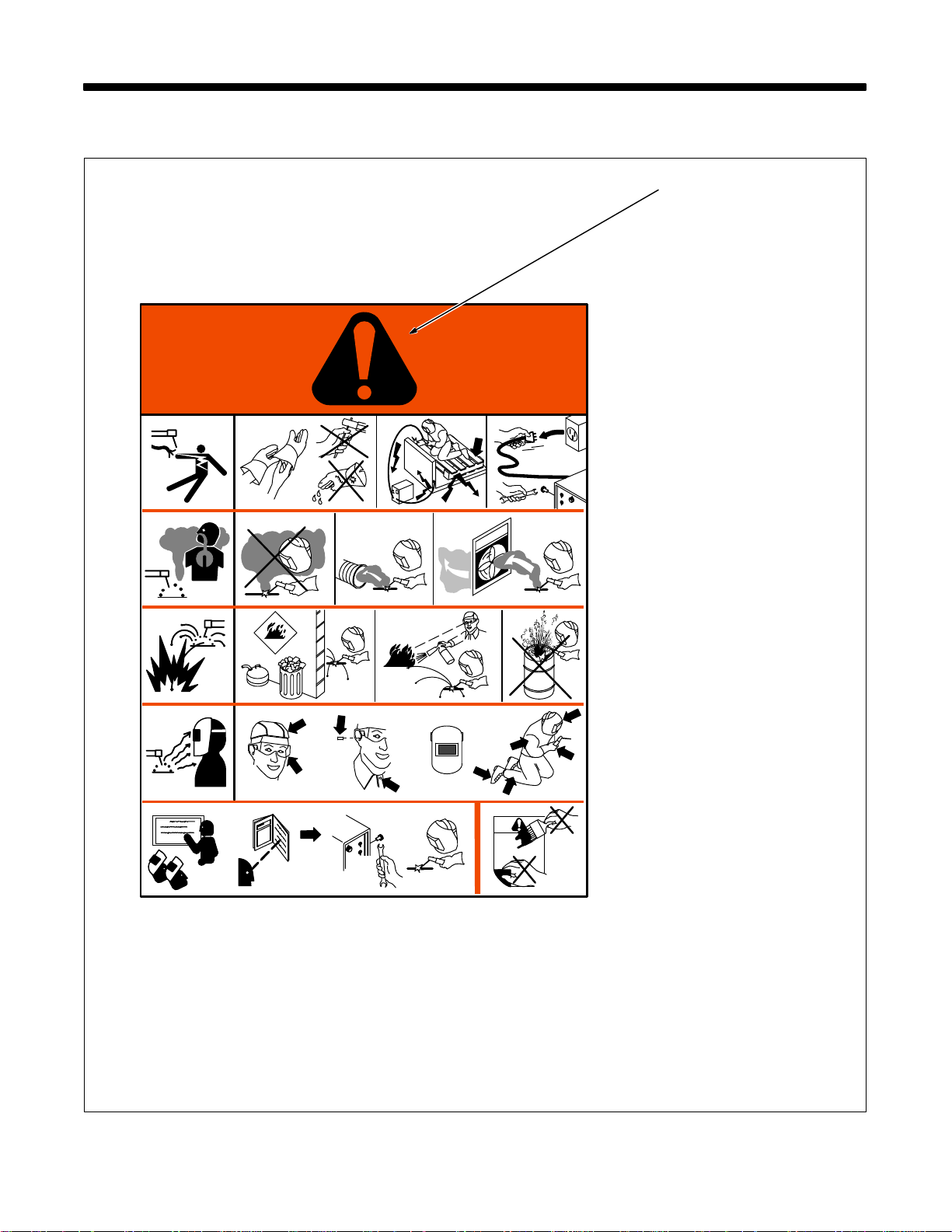
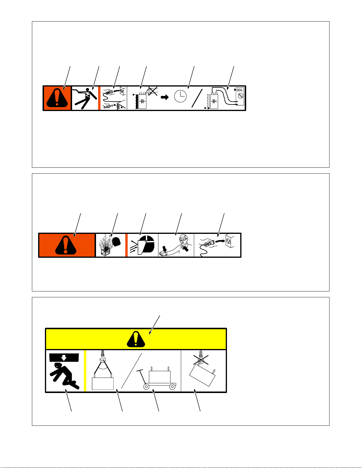
2-1. Manufacturer’s Warning Label Definitions
1 1.1 1.2 1.3
2 2.1
3 3.1 3.2 3.3
4 4.1
56
+
2.2
+
2.3
+
+
S-179 310
Warning! Watch Out! There are
possible hazards as shown by the
symbols.
1 Electric shock from welding
electrode or wiring can kill.
1.1 Wear dry insulating gloves.
Do not touch electrode with
bare hand. Do not wear wet or
damaged gloves.
1.2 Protect yourself from electric
shock by insulating yourself
from work and ground.
1.3 Disconnect input plug or
power before working on
machine.
2 Breathing welding fumes can
be hazardous to your health.
2.1 Keep your head out of the
fumes.
2.2 Use forced ventilation or local
exhaust to remove the fumes.
2.3 Use ventilating fan to remove
fumes.
3 Welding sparks can cause
explosion or fire.
3.1 Keep flammables away from
welding. Do not weld near
flammables.
3.2 Welding sparks can cause
fires. Have a fire extinguisher
nearby, and have a
watchperson ready to use it.
3.3 Do not weld on drums or any
closed containers.
4 Arc rays can burn eyes and
injure skin.
4.1 Wear hat and safety glasses.
Use ear protection and button
shirt collar. Use welding
helmet with correct shade of
filter. Wear complete body
protection.
5 Become trained and read the
instructions before working on
the machine or welding.
6 Do not remove or paint over
(cover) the label.
1/96
OM-196 188 Page 9
Page 16
1 Warning! Watch Out! There
2 Electric shock from wiring can
3 Disconnect input plug or
1234 5 6
4 Hazardous voltage remains
V
V
> 60 s
V
S-179 190-A
5 Always wait 60 seconds after
6 Check input capacitor voltage,
1 Warning! Watch Out! There
2 When power is applied failed
1 23 4 5
3 Flying pieces of parts can
4 Always wear long sleeves and
S-179 304-A
5 After taking proper
are possible hazards as
shown by the symbols.
kill.
power before working on
machine.
on input capacitors after
power is turned off. Do not
touch fully charged
capacitors.
power is turned off before
working on unit, OR
and be sure it is near 0 before
touching any parts.
4/96
are possible hazards as
shown by the symbols.
parts can explode or cause
other parts to explode.
cause injury. Always wear a
face shield when servicing
unit.
button your collar when
servicing unit.
precautions as shown,
connect power to unit.
2345
OM-196 188 Page 10
∠ = <60
∠
4/96
1 Warning! Watch Out! There
1
are possible hazards as
shown by the symbols.
2 Falling equipment can cause
injury and damage to unit.
3 Always lift and support unit
using both handles. Keep
angle of lifting device less
than 60 degrees.
°
4 Use a proper cart to move
unit.
5 Do not use one handle to lift
or support unit.
S-179 309-A
1/96
Page 17
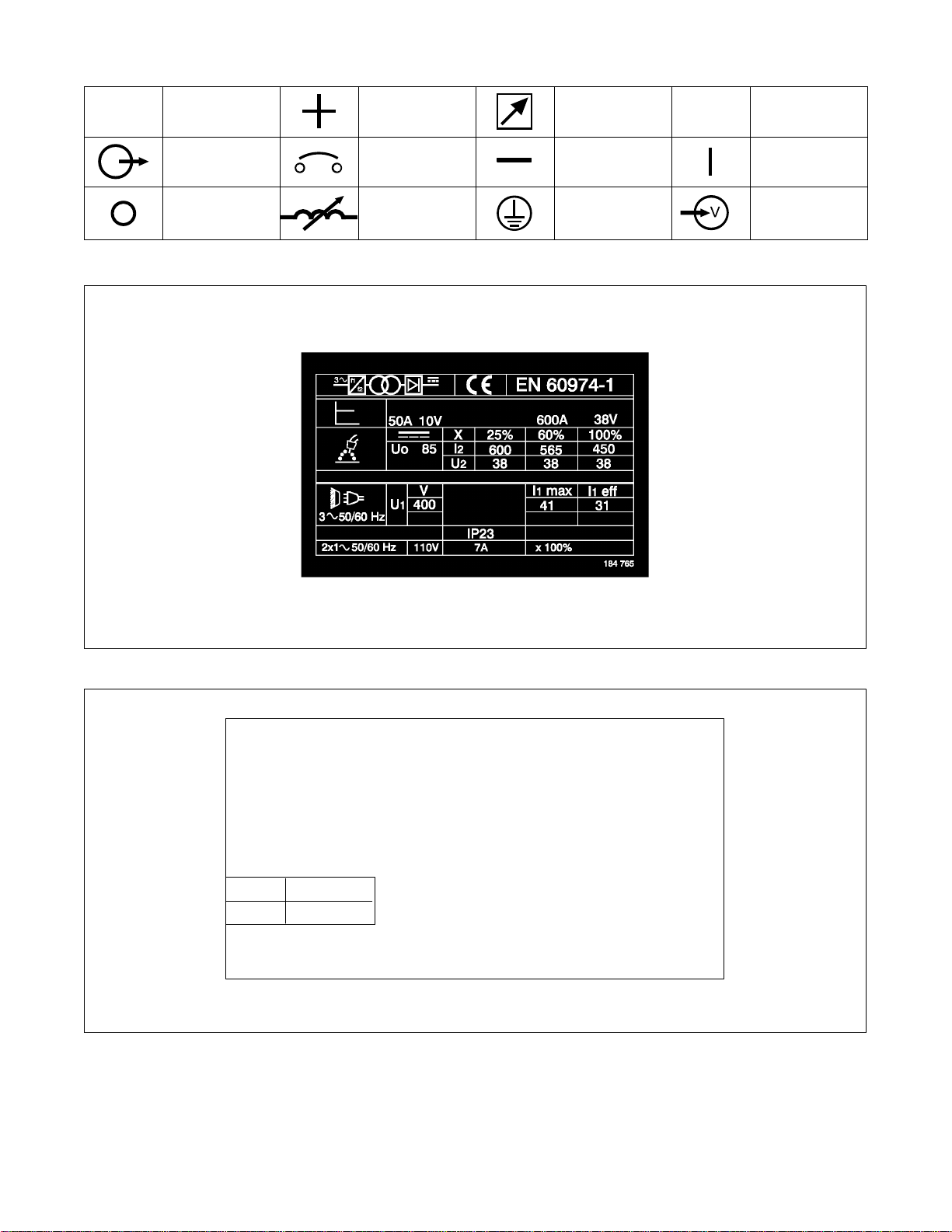
2-2. Symbols And Definitions
A
Amperage Positive Remote
Output Circuit Breaker Negative On
Off Inductance
2-3. Manufacturer’s Rating Label
Protective Earth
(Ground)
V
Voltage
Voltage Input
2-4. Harmonic Data
HARMONIC DATA per IEC 61000-3-12, draft 2000-9-29
PRIMARY; 400V/30.5A/60hz
LOAD; 450A/38Vdc/390IPM/,MAXIMUM OUTPUT, GMAW.
R sce = 227.28
THD
PWHD
Table 4, balanced three phase equipment.
S-184 765
61 Amps
35 Amps
OM-196 188 Page 11
Page 18
3-1. Specifications
Wire
Maximum
Amperes Input
Power
Output
Range
Range*
Diameter
Circuit
Output 60 Hz,
KVA
KW
450 A @ 38 Volts DC,
Three
450 A @ 38 Volts DC,
100% Duty Cycle;
Standard:
.030 To .062 in
Three
100% Duty Cycle;
,
10 – 38
50 To 780 ipm
.030 To .062 in
)
953121.6
19.4
Phase
565 A @ 43 Volts DC,
(1.3 To 19.8 mpm)
(0.8 To 1.6 mm)
A
(660 mm)
D
C
D
Input
Rated Welding
SECTION 3 – INSTALLATION
Voltage
Wire Feed Speed
Diameter
Range
Maximum
Open-
Voltage DC
Amperes Input
At Rated Load
Three-Phase
KVA KW
Phase
*Wire feed speed ranges are for GMAW welding. While pulse welding, wire feed speed ranges may be more limited (see Section 9)
**While idling
565 A @ 43 Volts DC
60% Duty Cycle
(0.8 To 1.6 mm
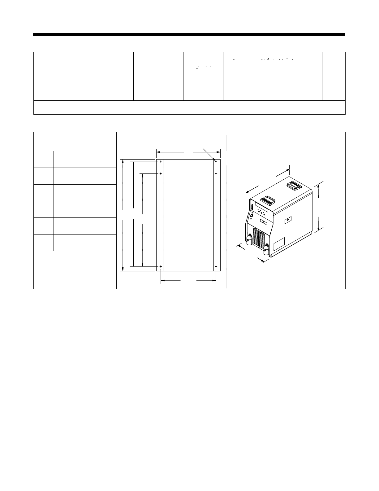
3-2. Dimensions And Weight
Hole Layout Dimensions
A 14-21/64 in (363.9 mm)
B 20-3/4 i n (527.1 mm)
C 23-27/64 in (594.9 mm)
D 24-31/32 in (634.2 mm)
C
B
E 12-3/8 i n (314.3 mm)
F 9/32 in (7.1 mm) Dia.
Weight
F
26 in
(660 mm)
14-1/2 i n
(368 mm)
23-3/4 in
(603 mm)
130 lb (59 kg)
E
801 914-A
OM-196 188 Page 12
Page 19
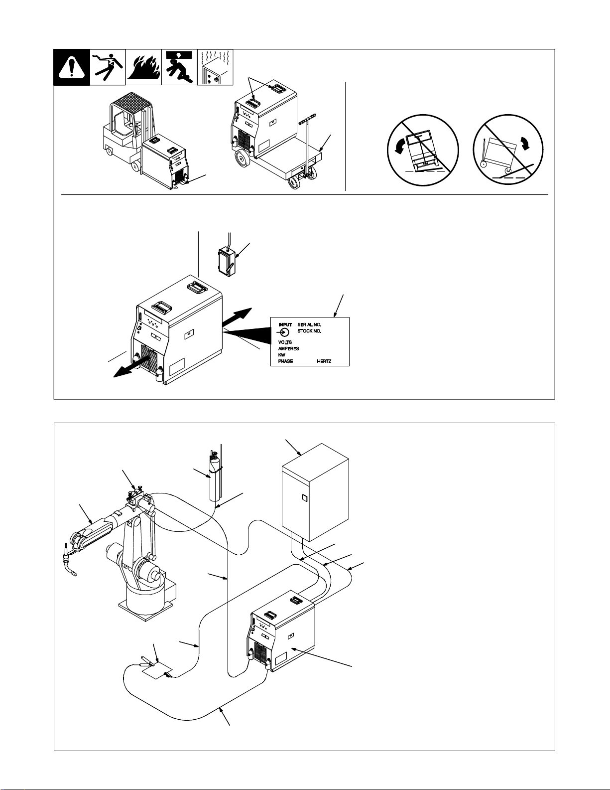
3-3. Selecting A Location
2
Movement
Location
18 in
(460 mm)
Tipping
3
OR
1
Y Special installation may be required where gasoline or volatile
liquids are present – see NEC Article 511 or CEC Section 20.
5
18 in
(460 mm)
4
Y Do not move or operate
unit where it could tip.
1 Lifting Forks
Use lifting forks to move unit.
Extend forks beyond opposite side
of unit.
2 Lifting Handles
Use handles to lift unit.
3 Hand Cart
Use cart or similar device to move
unit.
4 Rating Label
Use rating label to determine input
power needs.
5 Line Disconnect Device
Locate unit near correct input
power supply.
loc_2 3/96 - 801 958 / 801 914-A
3-4. Connection Diagram
2 3
1
13
11 12
5
4
6
7
8
. The proper interface kit must
be installed in the interface unit
to allow it to be connected to the
robot.
1 Robot (Will Vary According T o
Application)
2 Motor/Drive Assembly
3 Gas Cylinder
4 Gas Hose
5 Robot Control
6 Robot Input/Output Cable
7 Remote Program Select
Cable (Optional)
8 Gas And Motor Control Cable
9 Welding Power
Source/Interface Unit
10 Negative (–) Weld Cable
11 Workpiece
12 Voltage Sensing Lead
. Positive (+) voltage sensing
lead is contained in the motor
9
cable.
13 Positive (+) Weld Cable
10
801 915-B
OM-196 188 Page 13
Page 20
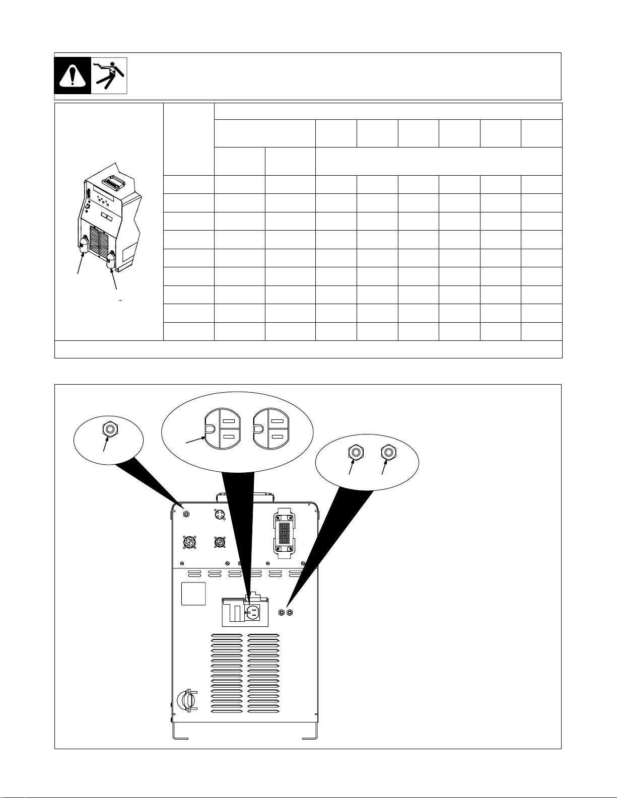
3-5. Weld Output Terminals And Selecting Cable Sizes
Positive
Positive
Negative
3-6. 115 Volts AC Duplex Receptacle And Circuit Breakers
Total Cable (Copper) Length In Weld Circuit Not Exceeding
30 m (100 ft) Or Less
Welding
Amperes
100 25 25 25 35 35 50 55 55
150 35 35 35 50 55 70 95 95
200 35 35 50 55 70 95 120 120
250 35 50 55 70 95 120 2-70 2-70
300 50 55 70 95 120 2-70 2-95 2-95
350 55 70 95 120 2-70 2-95 2-95 2-120
(+)
*Weld cable size (mm2) is based on either a 4 volts or less drop or a current density of at least 300 circular mils per ampere. S-0007E
Negative
(–)
Ref. 801 914-A
400 55 70 95 120 2-70 2-95 2-120 2-120
500 70 95 120 2-70 2-95 2-120 3-95 3-95
600 95 120 2-70 2-95 2-120 3-95 3-120 3-120
10 – 60%
Duty Cycle
60 – 100%
Duty Cycle
45 m
(150 ft)
1
4
60 m
(200 ft)
2 3
70 m
(250 ft)
10 – 100% Duty Cycle
90 m
(300 ft)
1 115 V 10 A AC Receptacle
Power is shared between duplex
receptacle and internal 14 socket
receptacle.
2 Circuit Breaker CB1
3 Circuit Breaker CB2
CB1 protects duplex receptacle
and 115 volts ac portion of internal
14 socket receptacle from
overload.
Press button to reset breaker.
CB2 protects 24 volts ac portion of
internal 14 socket receptacle from
overload.
Press button to reset breaker.
4 Circuit Breaker CB1
CB1 protects the motor control
circuitry from overload. If CB1 trips,
the wire drive motor is inoperative.
Press button to reset breaker.
105 m
(350 ft)
120 m
(400 ft)
OM-196 188 Page 14
802 748
Page 21
3-7. Electrical Service Guide
Three-Phase
Input Voltage 400
Input Amperes At Rated Output 31
Max Recommended Standard Fuse Or Circuit Breaker Rating In Amperes 45
Min Input Conductor Size In AWG/Kcmil 10
Max Recommended Input Conductor Length In Feet (Meters) 264 (80)
Min Grounding Conductor Size In AWG/Kcmil 10
Reference: 1993 National Electrical Code (NEC). S-0092J
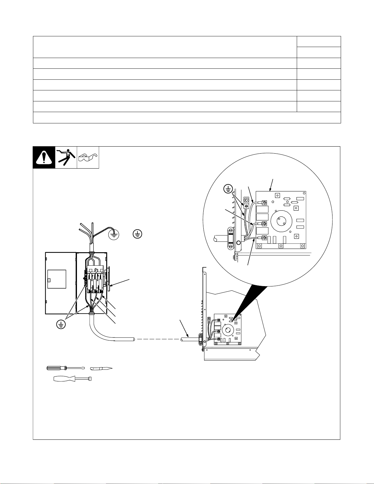
3-8. Connecting Input Power
Input Fi l t e r
Board
L1
Tools Needed:
5/16 in
Y Always connect
2
L1
L2
L3
L2
=GND/PE
grounding conductor
first.
L3
1
Y Turn Off welding power source, and
check voltage on input capacitors according to Section 5-3 before
proceeding.
Check input voltage available at site.
Remove left side panel.
1 Input And Grounding Conductors
See Section 3-7.
Install ring terminals of proper size onto input
conductors for connection to input filter
board terminals (see illustration).
2 Line Disconnect Device
ssb2.4* 1/94 – ST-801 718 / ST-801 946
Select type and size of overcurrent protection using Section 3-7. Connect input and
grounding conductors to a deenergized line
disconnect device.
Reinstall left side panel.
OM-196 188 Page 15
Page 22
3
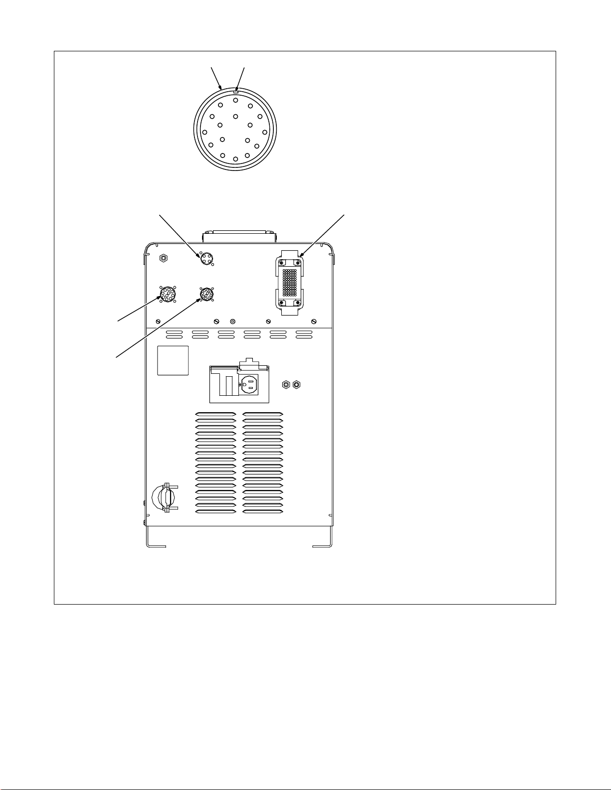
3-9. Rear Panel Connections
4
1
C
D
Example Receptacle
B
P
E
2
A
N
T
RS
G
F
M
L
K
J
H
1 Receptacle
2 Keyway
3 4-Pin Receptacle (Optional
External Voltage Sensing
Connection)
To connect interconnecting cord to
receptacle, align keyway, insert
plug, and tighten threaded collar.
Secure ring terminal on remaining
end of cord to work.
4 Peripheral Receptacle
Receptacle provides connection to
touch sensor, water flow switch, jog
+/–, and n/o relay contacts circuitry.
5
5 Robot Control Receptacle
(Remote Program Select
Connection To Robot Control)
To connect matching interconnecting cord to one of the above
receptacles, align keyway, insert
plug, and tighten threaded collar.
Connect remaining end of cord to
matching receptacle on applicable
equipment (see Section 3-4).
6 10-Socket Receptacle (Wire
Feed/Shielding Gas Control
Connection To Motor Drive
Assembly)
6
Ref. S-0003-A / 802 748
OM-196 188 Page 16
Page 23
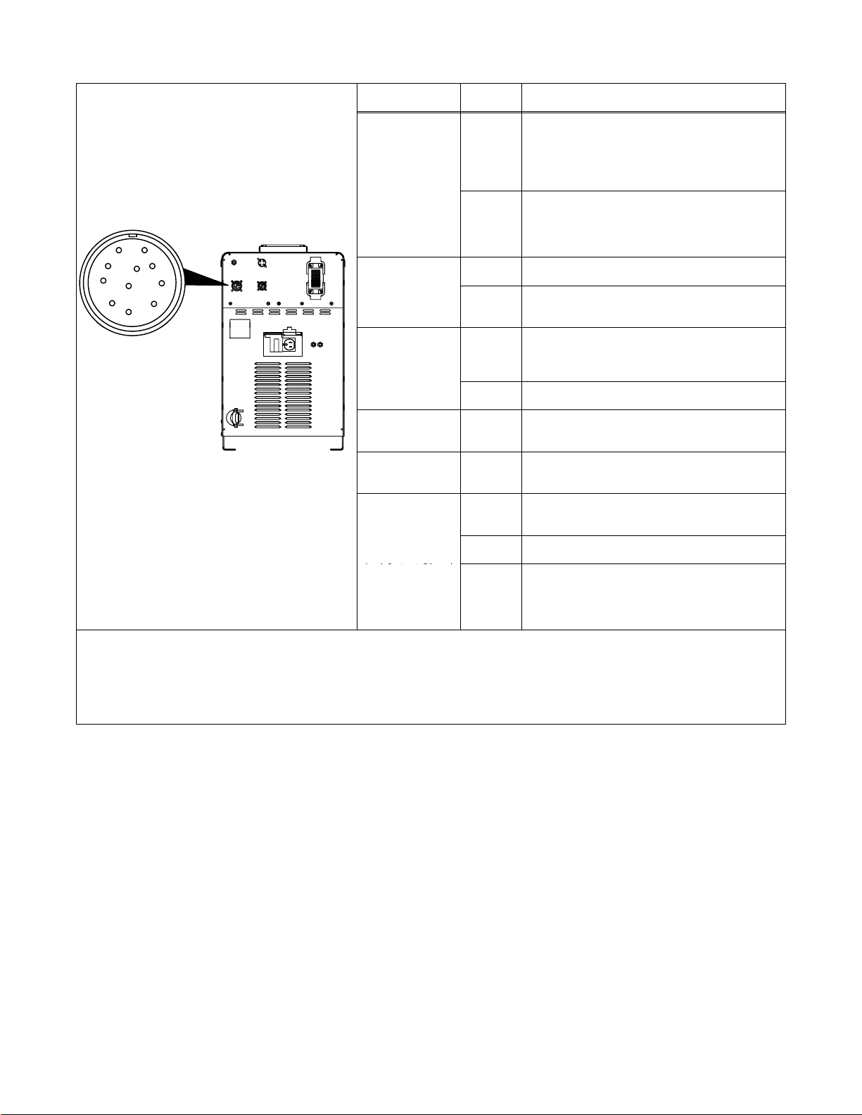
3-10. Peripheral Receptacle Functions
Output Relay Con-
AK
Output Relay Con-
AK
M
E
F
Signal
Touch Sensor ON
l
Programmable
B
C
D
J
M
L
H
F
E
Coolant Flow
Switch Input
Function Socket Socket Information
A Contact closure to B dependent upon state of
programmed output (see Section 14-5). The closure
between A and B can carry a maximum of 0.6
amps at 125 VAC; or a maximum of 0.6 amps at
110 VDC.
tacts
Purge
B Contact closure to A dependent upon state of
programmed output (see Section 14-5). See socket
A information for current carrying capacity of
closure.
C* Circuit common.
D Contact closure to C completes 24 volts dc
solenoid circuit to purge shielding gas line.
E Contact closure to F indicates coolant flow switch is
closed and recirculating coolant system is
operational.
F* Circuit common.
Jog + H** Contact closure to circuit common advances
Jog – J** Contact closure to circuit common retracts welding
802 748
Touch Sensor ON
And Output Signa
*Circuit common is same electrical reference point.
**Speed of Jog + and Jog – is at setup value for Jog IPM parameter.
{ Socket M can be changed to 0 volts dc (common) for part touched output signal (see Section 3-12).
Note: A customer supplied matching amphenol plug [Miller Part No. 194 847 (Amphenol Part No. MS3106A20-33P and strain relief clamp
AN3057-12)] is required to use peripheral receptacle.
M{ Part touched is selectable for either 0 volts dc
welding wire at wire drive assembly.
wire at wire drive assembly.
K Contact closure to L energizes Touch Sensor
circuitry.
L* Circuit common.
(common) or +24 volts dc (see Section 3-12).
Part touched +24 volts dc output signal referenced
to circuit common is factory default setting.
OM-196 188 Page 17
Page 24
3-11. Touch Sensor Operation
The touch sensor feature allows the robot to locate a weldment using the wire feed system and welding power source.
Voltage sense leads provide a path for touch sensor voltage when this feature is turned on at the peripheral receptacle.
Turning on touch sensor causes a dc voltage to be present on the welding wire. When welding wire touches the
weldment, the voltage sensing circuit closes, and a +24 volts dc output signal is sent to the robot control indicating
weldment detection. Touch sensor dc voltage on the welding wire will vary from 60 to 150 volts dc depending on the
welding power source. As soon as touch sensor turns on, DANGER SENSOR ON appears on the front panel display.
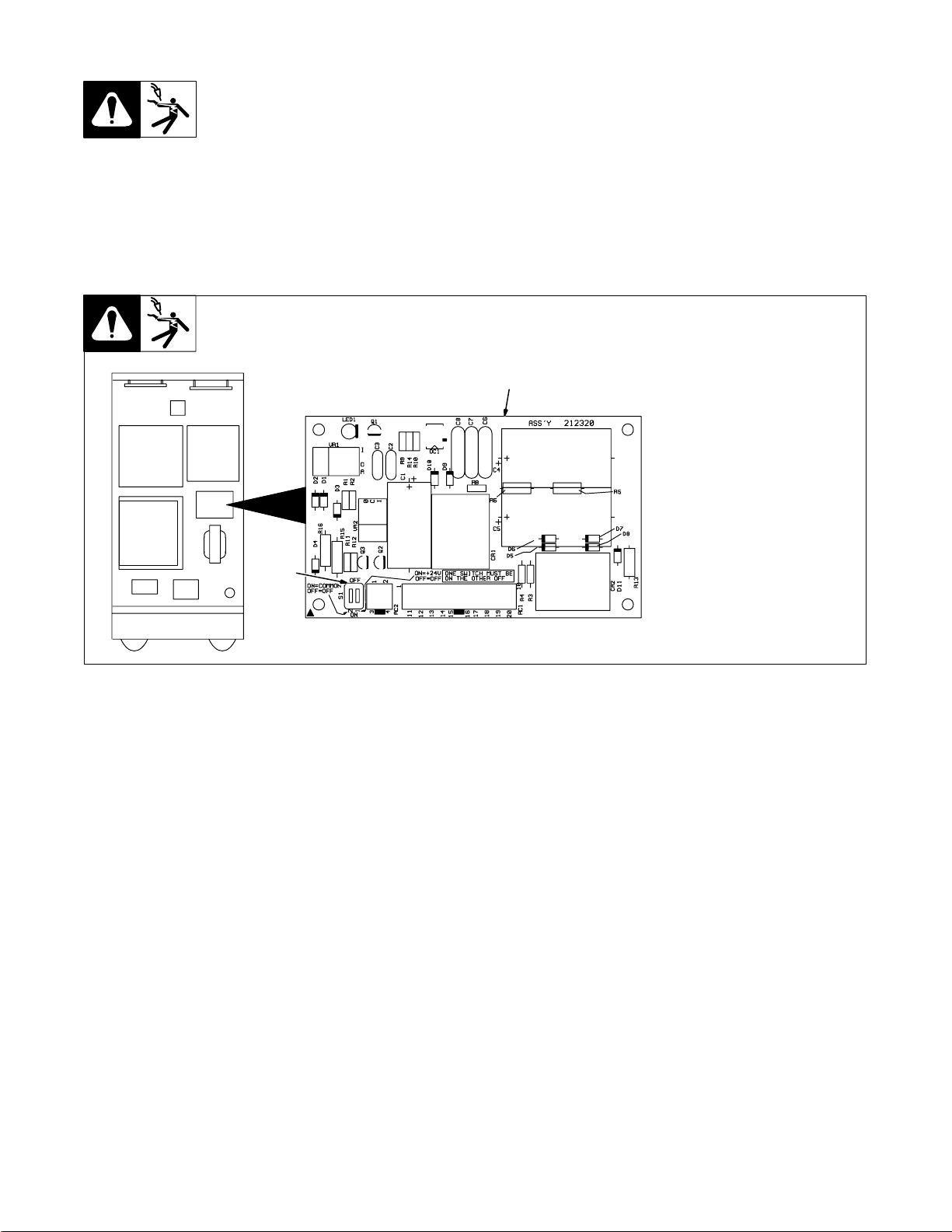
3-12. Touch Sensor Board PC18 Switch S1 Settings
Top View
Front
Y WARNING: One of S1 switches must be ON and
the other must be OFF.
1
2
1 Touch Sensor Board PC18
2 Switch S1
When S1 switch 1 is On, output is
+24 volts dc (factory default).
When S1 switch 2 is On, output is
common.
212 321-A
OM-196 188 Page 18
Page 25
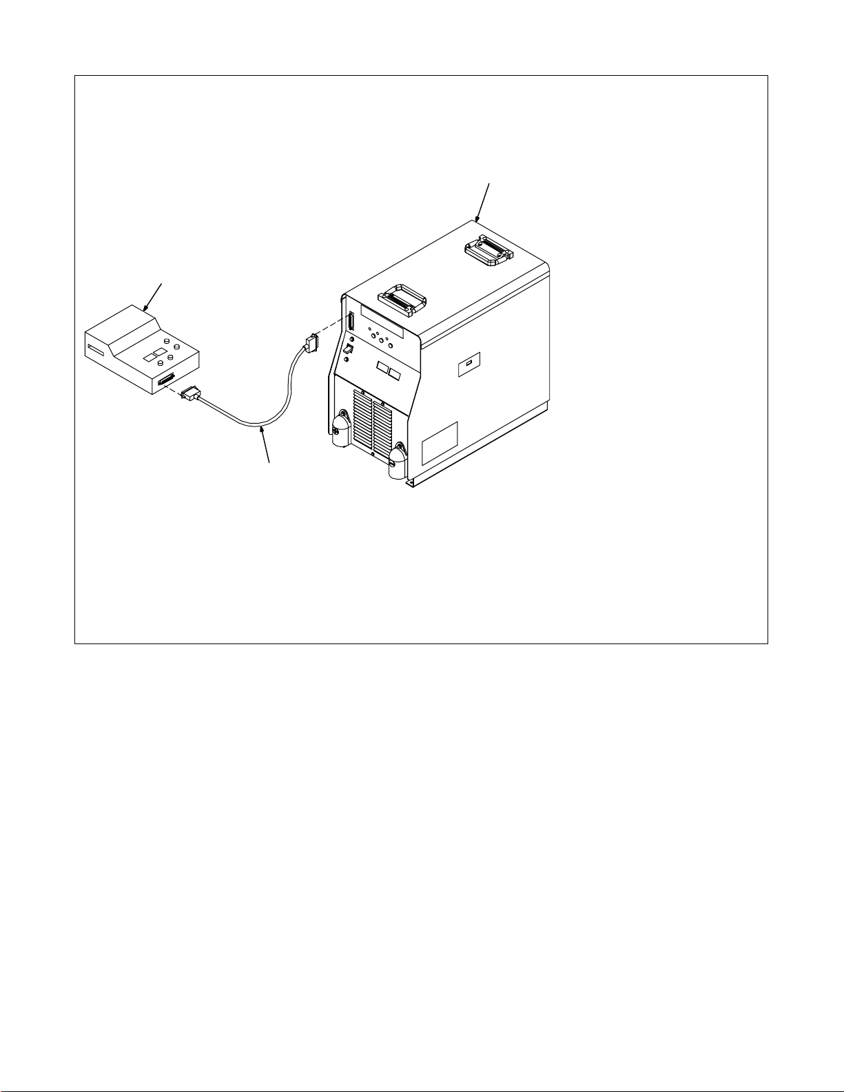
3-13. Connecting Setup Pendant To Welding Power Source
1
. Disconnect the setup pendant from the welding
power source before welding.
3
Y Turn Off welding power
source and weld control.
1 Welding Power Source
2 Interconnecting Cord
3 Setup Pendant
To make connections, align plug
with receptacle, insert plug, and
use thumb screws on receptacle to
secure plug.
2
802 816
OM-196 188 Page 19
Page 26

SECTION 4 – OPERATION
4-1. Operational Terms
The following is a list of terms and their definitions as they apply to this interface unit:
General Terms:
Adaptive Pulse Welding When the “adaptive pulse” welding process is selected, the unit will attempt to automatically regulate
Abk (Background Amperage) Abk is the low weld current. Background current preheats welding wire and maintains the arc. When
Apk (Peak Amperage) Apk is the high pulse of welding current. Peak current melts the welding wire and forms a droplet. The
Vpk (Peak Voltage) Arc voltage during peak current phase of the pulse waveform. This determines arc length during
Inductance In short circuit GMAW welding, an increase in inductance will decrease the number of short circuit
PPS (Pulses Per Second) PPS, pulse rate, and frequency (Hz) are used interchangeably. A PPS or pulse rate of 60 Hz means
PWms (Pulse Width in Milliseconds) PWms is the time spent at peak current (1.2 ms is .0012 seconds). This time must be long enough to
Synergic Synergic refers to the unit’s ability to use preprogrammed pulse parameters to determine the actual
Trim Term used to represent arc length adjustments in pulse programs. Increasing trim increases the ac-
pulse frequency in order to maintain a constant arc length, regardless of change in welding wire stickout.
background current is too low, the arc is unstable and hard to maintain.
droplet is forced into the weld puddle.
adaptive pulse welding.
metal transfers per second (provided no other changes are made) and increase the arc-on time. The
increased arc-on time makes the pool more fluid.
60 pulses of current are produced each second.
form a droplet of welding wire. The stiffness or fluidity of the molten weld puddle is controlled by
PWms.
pulse settings of Peak Amperage, Background Amperage, Pulse Frequency and Pulse Width at any
specific wire feed speed setting.
tual arc length. Likewise, decreasing trim shortens arc length. Trim is replaced by volts in MIG programs.
Setup Pendant Terms:
Card Mode Is used to select use of the optional data card storage and retrieval capabilities.
Process Mode Is used to select the type of process to be used, including Pulse, Adaptive Pulse, or Mig.
Sequence Mode Is used to select and program the weld sequences which include preflow, run-in, weld, crater,
Setup Screen Terms:
Access Code NOTE: The optional Data Card is required to activate this feature. With code off, access to the setup
Arc Start NOTE: Do not use the Hot Start setting for .035 in (9 mm) or smaller wire. Use the Hot Start mode for
Arc Time Allows actual arc time up to 9,999.99 hours and weld cycles up to 999,999 to be accumulated and
Mig Type (Voltage
Correction)
Name Feature When using the optional Data Card and turning the name feature on, programs written to the card can
Program Reset By selecting program reset in the memory reset mode, the unit defaults to original factory program
Range The interface requires that the voltage and amperage range of the welding power source be entered.
Security NOTE: The optional Data Card is required to activate this feature. Is used to limit what the operator
Software Screen Selection of this function will display the software version of the unit. When talking with factory service
OM-196 188 Page 20
burnback, and postflow.
displays is not restricted. With code on, the operator must know and enter the access code to access
or change any of the setup displays.
To use code, press Parameter Select button to enter access code. When the correct letter is entered,
the indicator automatically moves to the next character. When the final access code letter is entered,
the display automatically changes to the initial setup display.
pulse welding with 450 Ampere Inverter Model when high initial weld current is necessary to start
large diameter welding wires. When in Hot Start, the 450 Ampere Inverter Model starts the arc in the
CV mode and switches to CC once the arc is started. Do not use Hot Start unless using 450 Ampere
Inverter Model.
displayed on the digital display, and can be reset to zero as required.
With DVC Voltage Correction On, the unit uses closed-loop control based on voltage feedback to
maintain set voltage parameters. With DVC Voltage Correction Of f, feedback from the arc is not used
for closed-loop feedback to maintain voltage parameters. Feedback from the arc is still used for other
functions.
be identified by name, number, job number, etc.
settings for the program last active. All other program and setup information remains the same.
Obtain this information from the welding power source Owner’s Manual.
can control. This includes accessing the number of the program, 1 through 8, and the range of welding parameters within the program.
personnel, this number may be required.
Page 27
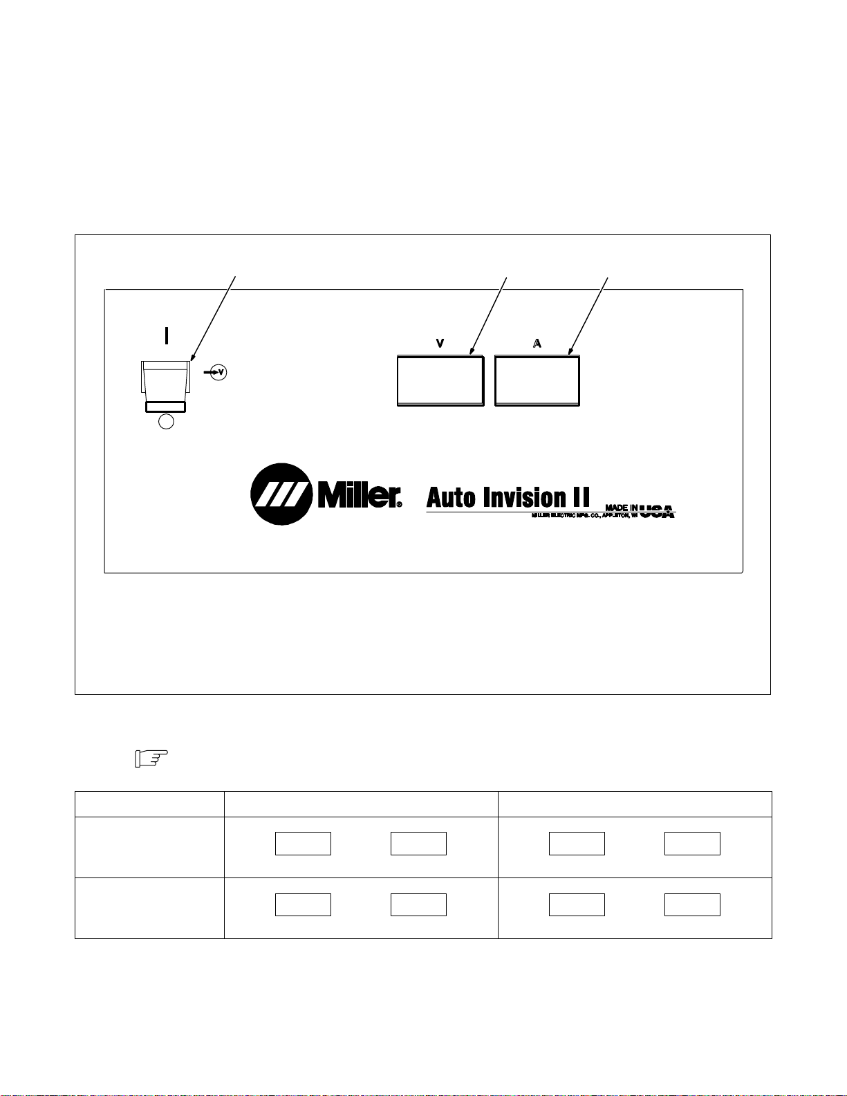
System Reset By selecting system reset in the memory reset mode, the unit defaults to original factory settings for
Voltage (Control Feedback) Allows voltage to be monitored at the output terminals by two methods. This can be selected through
Arc Start/Volt Sense Shutdown When this feature is on, the system immediately shuts down if no arc voltage is sensed. An error
Wire Feed Mode Allows the selection of inches per minute or meters per minute for wire feed speed. This mode is also
all programs and all set up excluding System, Arc Time, and Model T ype.
the internal connections of the unit, or through the unit’s external voltage sense lead.
When using the V . Sense setting, arc voltage feedback is through the voltage sense leads connected
to the feeder. Use this setting when there is more than 50 ft (15 m) of weld cable used.
message is displayed. When this feature is off, wire feeds even when there is no arc voltage sensed.
used to select motor type; standard speed, low speed, or high speed.
4-2. Lower Front Panel Controls
1
CE
1 Power Switch
. The fan motor is thermostatically
controlled and only runs when cooling is
needed.
23
2 Voltmeter (see Section 4-3) 3 Ammeter (see Section 4-3)
4-3. Meter Functions
Note
Mode Meter Reading At Idle Meter Reading While Welding
MIG
Pulsed
MIG
The meters display the actual weld output values for approximately three seconds after the arc
is broken.
VA
24.5
Preset Volts Blank
VA
PPP PPP
Pulse Display Pulse Display
Ref. 186 067
VA
24.5 250
Actual Volts Actual Amps
VA
24.5 250
Actual Volts Actual Amps
OM-196 188 Page 21
Page 28
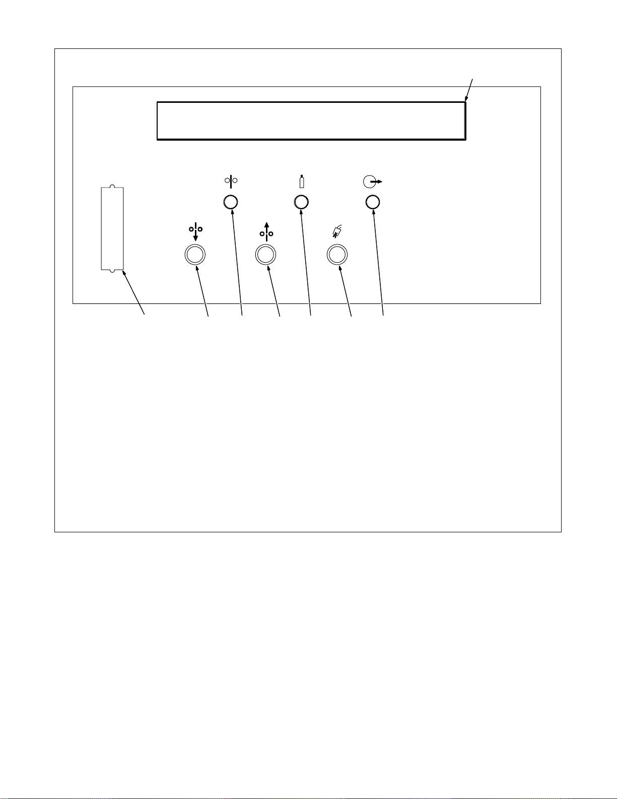
4-4. Upper Front Panel Controls
1 2 345 67
8
1 Setup Pendant Receptacle
Receptacle for connecting pendant
interconnecting cord.
2 Jog Forward Push Button
Advances wire out of the gun.
3 Wirefeed Indicator LED
LED lights when wire feed motor is
energized.
4 Jog Reverse Push Button
Retracts wire up into the gun.
5 Gas Indicator LED
LED lights when gas solenoid is energized.
6 Purge Push Button
Momentarily energizes gas solenoid to
purge air from gun shielding gas line, or to
adjust shielding gas regulator.
7 Contactor Indicator LED
LED lights when welding power source
contactor is energized.
8 Main Display
Shows system state, active program, error
messages, weld parameters at idle and
during welding.
184 197
OM-196 188 Page 22
Page 29
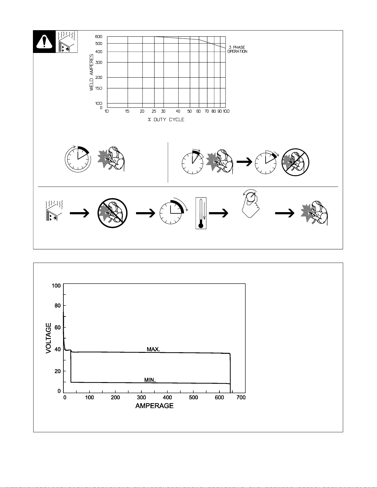
4-5. Duty Cycle And Overheating
4-6. Volt-Ampere Curves
100% Duty Cycle At 450 Amperes 60% Duty Cycle At 565 Amperes
Duty Cycle is percentage of 10 mi n utes that unit can weld at rated load
without overheating.
If unit overheats, thermostat(s)
opens, output stops, and cooling
fan runs. Wait fifteen minutes for
unit to cool. Reduce amperage or
duty cycle before welding.
Y Exceeding duty cycle can
damage unit and void warranty.
Continuous Welding
Overheating
0
Minutes
6 Minutes Welding 4 Minutes Resting
A/V
15
OR
Reduce Duty Cycle
duty1 4/95 – 181 560
Volt-ampere curves show minimum
and maximum voltage and amperage output capabilities of unit.
Curves of other settings fall between curves shown.
va_curve1 4/95 – 181 562
OM-196 188 Page 23
Page 30
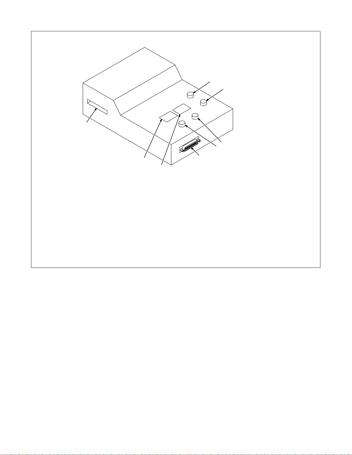
4-7. Setup Pendant Controls
8
1
2
3
4
7
6
5
802 815
1 Increase Button
Works with security feature on welding
power source to allow increasing weld
parameter values within the allowable range.
2 Decrease Button
Works with security feature on welding
power source to allow decreasing weld
parameter values within the allowable range.
3 Parameter Select Button
Press button to move indicator in right
window display, and to make selections in
setup screens.
4 Mode Select Button
Press button to move indicator in left window
display.
5 Interconnecting Cable Receptacle
6 Parameter Display
7 Mode Display
8 Card Slot
OM-196 188 Page 24
Page 31

SECTION 5 – MAINTENANCE & TROUBLESHOOTING
5-2. Blowing Out Inside Of Unit
5-1. Routine Maintenance
3 Months
Replace
damaged or
unreadable
label.
Repair or
replace cracked
cables and cords.
Clean an d
tighten weld
terminals.
Repair or
replace
cracked
cables.
Y Disconnect power
before maintaining.
6 Months
Blow out
inside.
. Maintain more often
during severe conditions.
Replace
cracked
torch body.
Y Do not remove case when
blowing out inside of unit.
To blow out unit, direct airflow
through front and back louvers as
shown.
801 914
OM-196 188 Page 25
Page 32

5-3. Removing Case and Measuring Input Capacitor Voltage
Y Significant DC voltage can remain on capacitors af-
ter unit is Off. Always check the voltage as shown
to be sure the input capacitors have discharged before working on unit.
Tools Needed:
5/16 in
1
1
Turn Off welding power source, a n d
disconnect input power.
1 Outside Handle Screws
To loosen top, remove two outside
handle screws from both handles
and all side bolts.
2 Interconnect Board PC2
3 Voltmeter
Measure the dc voltage across the
screw terminals on PC2 as shown
until voltage drops to near 0 (zero)
volts.
Proceed with job inside unit. Reinstall cover when finished.
2
+ lead to lower right
terminal, – lead to
upper right terminal
3
OM-196 188 Page 26
Ref. 801 914 / Ref. 801 917
Page 33

5-4. Voltmeter/Ammeter Help Displays
. All directions are in reference to
the front of the unit. All circuitry
referred to is located inside the
unit.
1 Help 1 Display
Indicates a malfunction in the
primary power circuit. If this display
is shown, contact a Factory
Authorized Service Agent.
2 Help 2 Display
Indicates a malfunction in the
thermal protection circuitry located
on the left side of the unit. If this
display is shown, contact a Factory
Authorized Service Agent.
3 Help 3 Display
Indicates the left side of the unit has
overheated. The unit has shut down
to allow the fan to cool it (see Section 4-5). Operation will continue
when the unit has cooled.
4 Help 4 Display
Indicates a malfunction in the
thermal protection circuitry located
on the right side of the unit. If this
display is shown, contact a Factory
Authorized Service Agent.
5 Help 5 Display
Indicates the right side of the unit
has overheated. The unit has shut
down to allow the fan to cool it (see
Section 4-5). Operation will
continue when the unit has cooled.
6 Help 6 Display
Indicates that the input voltage is
too low and the unit has
automatically shut down. Operation
will continue when the voltage is
within ±15% of the operating range.
If this display is shown, have an
electrician check the input voltage.
7 Help 7 Display
Indicates that the input voltage is
too high and the unit has
automatically shut down. Operation
will continue when the voltage is
within ±15% of the operating range.
If this display is shown, have an
electrician check the input voltage.
8 Help 8 Display
Indicates a malfunction in the sec-
ondary power circuit of the unit. If
this display is shown, contact a
Factory Authorized Service Agent.
In addition, when the optional
ground current sensor is installed,
this display indicates weld current
in the ground conductor. When this
occurs, have an electrician check
the primary and secondary
connections.
1
AV
HE.L P–1
AV
2
HE.L P–2
AV
3
HE.L P–3
AV
4
HE.L P–4
AV
5
HE.L P–5
AV
6
HE.L P–6
AV
7
HE.L P–7
AV
8
HE.L P–8
OM-196 188 Page 27
Page 34

5-5. Front Panel Error Displays
1
Mem CRC E r r o r
2
Mem Range Er r
3
No Vo l t Sensed Er ror
4
No Tach Sensed Er r or
5
Arc Stop Error
6
8
Er ror Card Read
9
No F l ow Det ec t ed
10
Grd Cur rent Detect
11
Wi re St i ck Er ror
12
Arc Fai l TimeOut Err
13
Arc Star t Error
7
Stop Weld Cycle Err
1 Memory CRC Error Display
Corrupted program data has been detected
or loaded. The “X” value indicates the program number.
May be caused by incompatible information
on the data card or bad memory.
2 Memory Range Error Display
Improper welding power source range is
selected. The “X” value indicates the program number.
May be caused by improper range settings
or improper data loaded into the interface
unit.
3 No Volt Sensed Error Display
The arc voltage sense circuit did not receive
feedback within the required time after an arc
was established.
May be caused by an inability to establish an
arc in the pulse schedule, or a lack of voltage
feedback.
4 No Tach Sensed Error Display
The motor tachometer feedback is not
reaching the control.
May be caused by obstructions in the wire
feed system or a faulty wire drive system.
5 Arc Stop Error Display
Trouble is occurring at arc end.
May be caused by obstructions in the wire
feed sys t e m o r a f a u l t y w i r e d r i v e s y s t e m o r
torch is touching part at end of weld.
6 Arc Start Error Display
Trouble is occurring at arc start.
May be caused by obstructions in the wire
feed system or a faulty wire drive system.
7 Stop Weld Cycle Error Display
An error has been detected and the robot
hasn’t stopped the weld cycle, causing the
interface unit to stop the weld cycle and wait
for the robot to stop.
8 Error Card Read Display
The card reader is not working properly.
May be caused by a bad data card, a bad
data card reader, a faulty microprocessor
circuit board, or a wiring problem.
9 No Flow Detected
No coolant is detected after preflow in the
weld cycle. Check coolant system and flow
switch for proper operation.
No Input IPM
10 Ground Current Detect Error Display
Weld current has been detected in the earth
ground connection.
May be caused by a conductor making
connection to the unit chassis.
11 Wire Stick Error Display
The welding wire has stuck to the workpiece
at the end of the weld.
May be caused by poor weld conditions.
12 Arc Fail Time Out Error Display
An arc was not established within the allotted
time.
May be caused by an inoperable wire drive,
absence of shield gas, or improperly operating welding power source.
13 No Input IPM Display
Analog IPM (inches per minute) from robot is
not being received.
May be caused by having no wire feed speed
programmed at the robot.
OM-196 188 Page 28
Page 35

5-6. Weld Interface Board PC12 Diagnostic LED’s
LED1
1
LED2
LED3
LED4
LED5
LED6
LED8
LED7
LED9
LED10
LED11
LED12
1 Weld Interface Board PC12
Diagnostic LED’s are visible inside
unit, located on PC12 (see illustration
for board location).
Refer to Section 5-7 for information
on diagnostic LED’s.
Reinstall cover and left side panel
after checking diagnostic LED’s.
LED13
Top View
191 842
OM-196 188 Page 29
Page 36

5-7. Diagnostic LED’s On Weld Interface Board PC12
LED Status Diagnosis
1 On Indicates auxiliary output relay is not energized.
Off Indicates auxiliary output relay is energized.
2 On Indicates gas valve is not energized.
Off Indicates gas valve is energized.
3 On Indicates +24 volts dc is present for gas valve.
Off Indicates +24 volts dc is not present for gas valve.
4 On Indicates +15 volts dc is present on weld interface board PC12.
Off Indicates +15 volts dc is not present on weld interface board PC12.
5 On Indicates –15 volts dc is present on weld interface board PC12.
Off Indicates –15 volts dc is not present on weld interface board PC12.
6 On Indicates +15 volts dc power source supply is present on weld interface board PC12.
Off Indicates +15 volts dc power source supply is not present on weld interface board PC12.
7 On Indicates –15 volts dc power source supply is present on weld interface board PC12.
Off Indicates –15 volts dc power source supply is not present on weld interface board PC12.
8 On Indicates +5 volts dc is present on weld interface board PC12.
Off Indicates +5 volts dc is not present on weld interface board PC12.
9 On Input signal for no Jog retract.
Off Input signal for Jog retract.
10 On Input signal for no Jog advance.
Off Input signal for Jog advance.
11 On Indicates CV mode is selected.
Off Indicates CC mode is selected.
12 On Input signal for no welding power source contactor.
Off Input signal for welding power source contactor.
13 On Indicates an Emergency Stop condition is not present.
Off Indicates an Emergency Stop condition is present.
OM-196 188 Page 30
Page 37

5-8. Customer Interface Board PC14 Diagnostic LED’s
LED8
LED11
LED12
LED13
LED6
1
LED5
LED7
LED10
LED9
LED14
LED15
1 Customer Interface Board PC14
Diagnostic LED’s are visible inside
unit, located on PC14 (see illustration
for board location).
Refer to Section 5-9 for information
on diagnostic LED’s.
Reinstall top cover after checking
diagnostic LED’s.
LED16
LED22
LED23
LED24
LED25
LED4
LED3
LED2
LED1
LED21
LED20
LED19
LED18
LED17
Top View
OM-196 188 Page 31
Page 38

5-9. Diagnostic LED’s On Customer Interface Board PC14
1
2
3
4
8
9
10
11
14
15
16
17
18
19
LED Status Diagnosis
On Indicates –15 volts dc RA supply is present on customer interface board PC14.
Off Indicates –15 volts dc RA supply is not present on customer interface board PC14.
On Indicates +15 volts dc RA supply is present on customer interface board PC14.
Off Indicates +15 volts dc RA supply is not present on customer interface board PC14.
On Input signal On from robot for no Emergency Stop.
Off Input signal Off from robot for Emergency Stop.
On Indicates +24 volts dc RD supply is present on customer interface board PC14.
Off Indicates +24 volts dc RD supply is not present on customer interface board PC14.
5 On Input signal On from robot for shielding gas.
Off Input signal Off from robot for no shielding gas.
6 On Input signal On from robot to energize contactor.
Off Input signal Off from robot to not energize contactor.
7 On Input signal On from robot for jog retract.
Off Input signal Off from robot for no jog retract.
On Input signal On from robot for jog advance.
Off Input signal Off from robot for no jog advance.
On Indicates automatic configuration Bit D is set.
Off Indicates automatic configuration Bit D is not set.
On Input signal On for RPS-C.
Off Input signal Off for RPS-C.
On Input signal On for RPS-B.
Off Input signal Off for RPS-B.
12 On Indicates remote program A selected.
Off Indicates remote program A not selected.
13 On Input signal On from peripheral for touch sensor.
Off Input signal Off from peripheral for no touch sensor.
On Indicates automatic configuration Bit B is set.
Off Indicates automatic configuration Bit B is not set.
On Indicates automatic configuration Bit A is set.
Off Indicates automatic configuration Bit A is not set.
On Indicates automatic configuration Bit C is set.
Off Indicates automatic configuration Bit C is not set.
On Input signal On from relay CR4 for wire stuck in weld joint.
Off Input signal Off from relay CR4 for wire not stuck in weld joint.
On Input signal On from relay CR6 for flow (shielding gas or coolant) present.
Off Input signal Off from relay CR6 for flow (shielding gas or coolant) not present.
On Input signal On from relay CR5 for arc detect.
Off Input signal Off from relay CR5 for no arc detect.
20 On Input signal On from relay CR2.
Off Input signal Off from relay CR2.
On Input signal On from relay CR1 for welding power source ready and no detected errors present.
21
22 On Input signal On from peripheral for flow switch.
Off Input signal Off from relay CR1 for welding power source not ready, detected errors are present, or unit
is in Setup or Control mode.
Off Input signal Off from peripheral for no flow switch.
OM-196 188 Page 32
Page 39

LED DiagnosisStatus
25
26
23 On Input signal On from peripheral for jog advance.
Off Input signal Off from peripheral for no jog advance.
24 On Input signal On from peripheral for jog retract.
Off Input signal Off from peripheral for no jog retract.
On Input signal On from peripheral for shielding gas purge.
Off Input signal Off from peripheral for no shielding gas purge.
On Input signal On for touch sensor.
Off Input signal Off for no touch sensor.
5-10. Motor Board PC13 Diagnostic LED’s
1 Motor Board PC13
Diagnostic LED’s are visible inside
unit, located on PC13 (see illustration
for board location).
Refer to Section 5-11 for information
on diagnostic LED’s.
Reinstall cover after checking
diagnostic LED’s.
LED1
Top View
LED2
LED9
1
LED4
LED3 LED11
212 353-A
OM-196 188 Page 33
Page 40

5-11. Diagnostic LED’s On Motor Board PC13
LED Status Diagnosis
1 On Indicates motor reverse relay is energized.
Red Off Indicates motor reverse relay is not energized.
2 On LED should be On. Indicates 115 volts ac input is sufficiently charging +170 volts dc bus for motor.
Red Off If LED is Of f, check 115 volts ac input.
9 On LED should be On. Indicates +15 volts dc regulated bus is on.
Red Off If LED is Of f, check for a short at board traces between bus and ground or at RC1-6 for 24 volts ac input
11 On LED should be On. Indicates +5 volts dc regulated bus is on.
Red
4 On Indicates encoder input from motor to microprocessor is greater than 3 ipm.
Green Off Indicates motor is off or encoder input from motor to microprocessor is less than 3 ipm.
3 On Indicates microprocessor is operating without sensing any faults.
Green Blinking If microprocessor senses a fault, LED blinks to indicate type of fault.
Off If LED is Off, check for a short at board traces between bus and ground or at RC1-6 for 24 volts ac input
3 Blinks PC13 sensed an overcurrent condition in wire drive. Check motor cables and connections for short cir-
4 Blinks PC13 PWM (pulse width modulation) output was on, but no encoder pulses were sensed for more than
5 Blinks Motor was not operating at proper speed for over 2 seconds. This fault results from monitoring amount of
6 Blinks +170 volts dc motor bus has dropped below +90 volts dc. Check 115 volts ac input to PC13.
to regulator.
to regulator.
cuits or bad connections. Check motor armature resistance, typical range is 10 to 20 ohms.
1 second. Check motor cables and connections for short circuits or bad connections. Electronic resetable
fuses called PTCs protect encoder power supply . If motor cable has a short circuit, PTCs will g o t o high
resistance to protect PC13. Do a pin-to-pin check for shorted conductors inside cable jacket, and replace
cable if necessary. Check motor encoder, and replace encoder if necessary.
velocity error (command speed – actual speed) to make sure that motor is running within a calculated percentage o f command speed. For example, if motor is at a high speed and PWM is at maximum voltage,
a dirty liner or other load drags down motor speed will result in this fault condition. Clean liner, correct other
load conditions, such as spool hub tension too tight, or reduce wire feed speed.
5-12. Troubleshooting
Trouble Remedy
No weld output; unit completely
inoperative.
No weld output; meter display On. Check, repair, or replace remote control.
Erratic or improper weld output. Use proper size and type of weld cable (see Section 3-5).
No 115 volts ac output at duplex
receptacle, Remote 14 receptacle.
No 24 volts ac output at Remote 14 receptacle.
Place line disconnect switch in On position (see Section 3-8).
Check and replace line fuse(s), if necessary, or reset circuit breaker (see Section 3-8).
Check for proper input power connections (see Section 3-8).
Unit overheated. Allow unit to cool with fan On (see Section 4-5).
Check voltmeter/ammeter Help displays.
Clean and tighten all weld connections.
Reset circuit breaker CB1 (see Section 3-6).
Reset circuit breaker CB2 (see Section 3-6).
OM-196 188 Page 34
Page 41

Notes
OM-196 188 Page 35
Page 42

SECTION 6 – ELECTRICAL DIAGRAMS
OM-196 188 Page 36
Figure 6-1. Circuit Diagram For Welding Power Source
Page 43

203 505-A
OM-196 188 Page 37
Page 44

OM-196 188 Page 38
Figure 6-2. Circuit Diagram For Control Board PC1 (Part 1 of 3)
Page 45

203 311 (1 of 3)
OM-196 188 Page 39
Page 46

OM-196 188 Page 40
Figure 6-3. Circuit Diagram For Control Board PC1 (Part 2 of 3)
Page 47

203 311 (2 of 3)
OM-196 188 Page 41
Page 48

OM-196 188 Page 42
Figure 6-4. Circuit Diagram For Control Board PC1 (Part 3 of 3)
Page 49

203 311 (3 of 3)
OM-196 188 Page 43
Page 50

OM-196 188 Page 44
Figure 6-5. Circuit Diagram For Function/Meter Board PC3
Page 51

190 696
OM-196 188 Page 45
Page 52

Figure 6-6. Circuit Diagram For Interconnect Board PC2
184 183
OM-196 188 Page 46
188 015
Figure 6-7. Circuit Diagram For Gate Boards PC4 And PC5
Page 53

Notes
OM-196 188 Page 47
Page 54

OM-196 188 Page 48
Figure 6-8. Circuit Diagram For Interface Module
Page 55

193 709-A
OM-196 188 Page 49
Page 56

OM-196 188 Page 50
Figure 6-9. Circuit Diagram For Microprocessor Board PC11
Page 57

191 838
OM-196 188 Page 51
Page 58

OM-196 188 Page 52
Figure 6-10. Circuit Diagram For Motor Board PC13
Page 59

OM-196 188 Page 53
212 354-A
Page 60

OM-196 188 Page 54
182 996
Figure 6-11. Circuit Diagram For Switch Board PC15
Page 61

Figure 6-12. Circuit Diagram For Junction Board PC16
200 739
OM-196 188 Page 55
Page 62

OM-196 188 Page 56
Figure 6-13. Circuit Diagram For Interface Board PC12 (Part 1 of 2)
Page 63

191 843-A (Part 1 of 2)
OM-196 188 Page 57
Page 64

OM-196 188 Page 58
Figure 6-14. Circuit Diagram For Interface Board PC12 (Part 2 of 2)
Page 65

191 843-A (Part 2 of 2)
OM-196 188 Page 59
Page 66

Figure 6-15. Circuit Diagram For Customer Interface Board PC14 (Part 1 of 3)
OM-196 188 Page 60
Page 67

Pensar 86147s03 (Part 1 of 3)
OM-196 188 Page 61
Page 68

Figure 6-16. Circuit Diagram For Customer Interface Board PC14 (Part 2 of 3)
OM-196 188 Page 62
Page 69

Pensar 86147s03 (Part 2 of 3)
OM-196 188 Page 63
Page 70

Figure 6-17. Circuit Diagram For Customer Interface Board PC14 (Part 3 of 3)
OM-196 188 Page 64
Page 71

Pensar 86147s03 (Part 3 of 3)
OM-196 188 Page 65
Page 72

Figure 6-18. Circuit Diagram For Touch Sensor Board PC18
174 578-A
OM-196 188 Page 66
Page 73

Figure 6-19. Circuit Diagram For Setup Pendant
200 739-A
OM-196 188 Page 67
Page 74

Figure 6-20. Circuit Diagram For Setup Pendant Centronix Junction Board PC3
OM-196 188 Page 68
200 739
Page 75

Figure 6-21. Circuit Diagram For Power Distribution Board PC20
191 531
OM-196 188 Page 69
Page 76

SECTION 7 – PARTS LIST
34
91
28
29
33
27
31
26
24
25
32
30
23
35
36
37
38
22
39
21
40
20
41
19
18
14
17
42
15
43
16
44
45
46
52
51
47
50
53
48
. Hardware is common and
not available unless listed.
88
55
54
56
49
9
69
67
57
58
59
60
61
62
89
13
12
11
92
2
1
10
9
5
69
71
72
73
90
74
8
7
6
87
86
70
81
76
78
75
77
68
79
85
80
81
84
66
82
83
65
64
63
802 872-D
Figure 7-1. Complete Assembly
OM-196 188 Page 70
Page 77

Part
Dia.
Item
No.
ty
Mkgs.
No.
Description
Quanti
Figure 7-1. Complete Assembly
1 185 970 COVER, top 1. . . . . . . . . . . . . . . . . . . . . . . . . . . . . . . . . . . . . . . . . . . . . . . . . . . . . . . . . . . . . . . . . . . . . . . .
2 195 585 HANDLE, carrying rubber 2. . . . . . . . . . . . . . . . . . . . . . . . . . . . . . . . . . . . . . . . . . . . . . . . . . . . . . . . . . . .
5 179 310 LABEL, warning general precautionary 2. . . . . . . . . . . . . . . . . . . . . . . . . . . . . . . . . . . . . . . . . . . . . . . . .
6 183 827 BUS BAR, output 1. . . . . . . . . . . . . . . . . . . . . . . . . . . . . . . . . . . . . . . . . . . . . . . . . . . . . . . . . . . . . . . . . . .
7 HD1 168 829 TRANSDUCER, current 600A 1. . . . . . . . . . . . . . . . . . . . . . . . . . . . . . . . . . . . . . . . . . . . . . . . . . .
PLG19 115 094 HOUSING PLUG & SOCKETS 1. . . . . . . . . . . . . . . . . . . . . . . . . . . . . . . . . . . . . . . . . . . . . . . . . .
8 +179 902 WINDTUNNEL, LH 1. . . . . . . . . . . . . . . . . . . . . . . . . . . . . . . . . . . . . . . . . . . . . . . . . . . . . . . . . . . . . . . .
9 185 836 LABEL, warning electric shock 3. . . . . . . . . . . . . . . . . . . . . . . . . . . . . . . . . . . . . . . . . . . . . . . . . . . . . . . .
10 T1 185 524 TRANSFORMER, HF 1. . . . . . . . . . . . . . . . . . . . . . . . . . . . . . . . . . . . . . . . . . . . . . . . . . . . . . . . . . .
11 FM2 183 918 MOTOR, fan 24VDC 3000RPM 43CFM w/10 ohm resistor 1. . . . . . . . . . . . . . . . . . . . . . . . . .
12 194 450 BRACKET, mtg capacitor/PC board/fan 1. . . . . . . . . . . . . . . . . . . . . . . . . . . . . . . . . . . . . . . . . . . . . . . .
13 PC1 203 309 CIRCUIT CARD ASSEMBLY, control (400 volt model) 1. . . . . . . . . . . . . . . . . . . . . . . . . . . . . .
PLG2 115 092 HOUSING PLUG & SOCKETS 1. . . . . . . . . . . . . . . . . . . . . . . . . . . . . . . . . . . . . . . . . . . . . . . . . . . .
PLG3 130 203 HOUSING PLUG & SOCKETS 1. . . . . . . . . . . . . . . . . . . . . . . . . . . . . . . . . . . . . . . . . . . . . . . . . . . .
PLG5 113 752 HOUSING PLUG & SOCKETS 1. . . . . . . . . . . . . . . . . . . . . . . . . . . . . . . . . . . . . . . . . . . . . . . . . . . .
PLG7 115 094 HOUSING PLUG & SOCKETS 1. . . . . . . . . . . . . . . . . . . . . . . . . . . . . . . . . . . . . . . . . . . . . . . . . . . .
PLG21 211 138 PLUG, w/leads 1. . . . . . . . . . . . . . . . . . . . . . . . . . . . . . . . . . . . . . . . . . . . . . . . . . . . . . . . . . . . . . . . .
14 194 371 SPACER, al 3.500 log 1. . . . . . . . . . . . . . . . . . . . . . . . . . . . . . . . . . . . . . . . . . . . . . . . . . . . . . . . . . . . . . .
15 C3-6 192 935 CAPACITOR, elctlt 2700uf 420 4. . . . . . . . . . . . . . . . . . . . . . . . . . . . . . . . . . . . . . . . . . . . . . . . .
16 144 842 ACTUATOR, switch 3. . . . . . . . . . . . . . . . . . . . . . . . . . . . . . . . . . . . . . . . . . . . . . . . . . . . . . . . . . . . . . . . .
17 209 310 NAMEPLATE, front upper 1. . . . . . . . . . . . . . . . . . . . . . . . . . . . . . . . . . . . . . . . . . . . . . . . . . . . . . . . . . . .
18 201 387 CIRCUIT CARD ASSY, connector 1. . . . . . . . . . . . . . . . . . . . . . . . . . . . . . . . . . . . . . . . . . . . . . . . . . . . .
19 208 824 PANEL, front 1. . . . . . . . . . . . . . . . . . . . . . . . . . . . . . . . . . . . . . . . . . . . . . . . . . . . . . . . . . . . . . . . . . . . . . .
20 PC17 203 663 DISPLAY, vfd dotmatrix 1x20 alphanumeric 20 pin 1. . . . . . . . . . . . . . . . . . . . . . . . . . . . . . . . .
21 PC15 182 998 CIRCUIT CARD ASSY, switch board 1. . . . . . . . . . . . . . . . . . . . . . . . . . . . . . . . . . . . . . . . . . . . .
22 193 716 PANEL, center 1. . . . . . . . . . . . . . . . . . . . . . . . . . . . . . . . . . . . . . . . . . . . . . . . . . . . . . . . . . . . . . . . . . . . . .
23 PC20 191 533 CIRCUIT CARD ASSY, power distribution 1. . . . . . . . . . . . . . . . . . . . . . . . . . . . . . . . . . . . . . . .
24 T11 193 706 TRANSFORMER, control 1. . . . . . . . . . . . . . . . . . . . . . . . . . . . . . . . . . . . . . . . . . . . . . . . . . . . . . .
25 PC16 201 387 CIRCUIT CARD ASSY, junction board 1. . . . . . . . . . . . . . . . . . . . . . . . . . . . . . . . . . . . . . . . . . .
26 PC12 191 841 CIRCUIT CARD ASSY, interface board 1. . . . . . . . . . . . . . . . . . . . . . . . . . . . . . . . . . . . . . . . . . .
27 097 132 STAND-OFF, No. 6-32 x .375 28. . . . . . . . . . . . . . . . . . . . . . . . . . . . . . . . . . . . . . . . . . . . . . . . . . . . . . . . .
28 PC11 202 005 CIRCUIT CARD ASSY, micro board 1. . . . . . . . . . . . . . . . . . . . . . . . . . . . . . . . . . . . . . . . . . . . .
29 PC14 203 665 CIRCUIT CARD ASSY, customer interface 1. . . . . . . . . . . . . . . . . . . . . . . . . . . . . . . . . . . . . . .
30 PC18 212 320 CIRCUIT CARD ASSY, touch sensor 1. . . . . . . . . . . . . . . . . . . . . . . . . . . . . . . . . . . . . . . . . . . .
31 PC13 213 193 CIRCUIT CARD ASSY, motor board 1. . . . . . . . . . . . . . . . . . . . . . . . . . . . . . . . . . . . . . . . . . . . .
32 PC21 200 077 CIRCUIT CARD ASSY, filter board 1. . . . . . . . . . . . . . . . . . . . . . . . . . . . . . . . . . . . . . . . . . . . . .
33 195 994 PANEL, rear 1. . . . . . . . . . . . . . . . . . . . . . . . . . . . . . . . . . . . . . . . . . . . . . . . . . . . . . . . . . . . . . . . . . . . . . . .
34 RC70 201 058 CONNECTOR, receptacle 72-pin 1. . . . . . . . . . . . . . . . . . . . . . . . . . . . . . . . . . . . . . . . . . . . . . . .
35 RC8 200 591 CONNECTOR, circ ms/met 11 pin 1. . . . . . . . . . . . . . . . . . . . . . . . . . . . . . . . . . . . . . . . . . . . . . .
36 RC21 200 589 CONNECTOR, circ ms/met 10 pin 1. . . . . . . . . . . . . . . . . . . . . . . . . . . . . . . . . . . . . . . . . . . . . . .
37 RC25 200 082 CONNECTOR, circ ms/met 4 pin size 14s 1. . . . . . . . . . . . . . . . . . . . . . . . . . . . . . . . . . . . . . . .
38 PC19 134 560 CIRCUIT CARD ASSY, filter board 1. . . . . . . . . . . . . . . . . . . . . . . . . . . . . . . . . . . . . . . . . . . . . .
39 CB11 011 991 CIRCUIT BREAKER, man reset 1P 1.5A 250 VAC 1. . . . . . . . . . . . . . . . . . . . . . . . . . . . . . . . .
40 PC22 200 073 CIRCUIT CARD 1. . . . . . . . . . . . . . . . . . . . . . . . . . . . . . . . . . . . . . . . . . . . . . . . . . . . . . . . . . . . . . .
41 CR12 187 252 SWITCH, reed 1. . . . . . . . . . . . . . . . . . . . . . . . . . . . . . . . . . . . . . . . . . . . . . . . . . . . . . . . . . . . . . . .
42 RC9 134 734 CONNECTOR, circ ms/cpc 14 pin size 20 1. . . . . . . . . . . . . . . . . . . . . . . . . . . . . . . . . . . . . . . .
079 739 CONNECTOR, clamp 1. . . . . . . . . . . . . . . . . . . . . . . . . . . . . . . . . . . . . . . . . . . . . . . . . . . . . . . . . . . . . . . . . . .
43 RC1 134 735 CONNECTOR, circ ms/cpc 14 skt size 20 1. . . . . . . . . . . . . . . . . . . . . . . . . . . . . . . . . . . . . . . .
44 L1 180 026 INDUCTOR, input 1. . . . . . . . . . . . . . . . . . . . . . . . . . . . . . . . . . . . . . . . . . . . . . . . . . . . . . . . . . . . . . .
45 Z1 180 029 STABILIZER, output 1. . . . . . . . . . . . . . . . . . . . . . . . . . . . . . . . . . . . . . . . . . . . . . . . . . . . . . . . . . . . .
46 181 925 INSULATOR, stabilizer lead 1. . . . . . . . . . . . . . . . . . . . . . . . . . . . . . . . . . . . . . . . . . . . . . . . . . . . . . . . . .
OM-196 188 Page 71
Page 78

Part
Dia.
Item
No.
ty
Mkgs.
No.
Description
Quanti
Figure 7-1. Complete Assembly (Continued)
47 T2 185 231 TRANSFORMER, control 200/400 VAC 1. . . . . . . . . . . . . . . . . . . . . . . . . . . . . . . . . . . . . . . . . . . .
RC10 166 679 HOUSING RECEPTACLE PINS & SOCKETS 1. . . . . . . . . . . . . . . . . . . . . . . . . . . . . . . . . . . . . . . .
48 180 105 BRACKET, mtg transformer aux 1. . . . . . . . . . . . . . . . . . . . . . . . . . . . . . . . . . . . . . . . . . . . . . . . . . . . . . .
49 +194 449 WINDTUNNEL, RH 1. . . . . . . . . . . . . . . . . . . . . . . . . . . . . . . . . . . . . . . . . . . . . . . . . . . . . . . . . . . . . . . .
50 RC2 604 176 RECEPTACLE, str dx grd 2P3W 15A 125V 1. . . . . . . . . . . . . . . . . . . . . . . . . . . . . . . . . . . . . . .
175 282 COVER, receptacle weatherproof 1. . . . . . . . . . . . . . . . . . . . . . . . . . . . . . . . . . . . . . . . . . . . . . . . . . . . . . . .
51 CB1 161 078 CIRCUIT BREAKER, man reset 1P 7A 250 VAC 1. . . . . . . . . . . . . . . . . . . . . . . . . . . . . . . . . .
52 CB2 093 995 CIRCUIT BREAKER, man reset 1P 15A 250 VAC 1. . . . . . . . . . . . . . . . . . . . . . . . . . . . . . . . .
53 179 847 PLATE, identification (order by model & serial number) 1. . . . . . . . . . . . . . . . . . . . . . . . . . . . . . . . . . .
54 195 847 PANEL, rear 1. . . . . . . . . . . . . . . . . . . . . . . . . . . . . . . . . . . . . . . . . . . . . . . . . . . . . . . . . . . . . . . . . . . . . . . .
55 W1 180 270 CONTACTOR, def prp 40A 3P 24VAC 1. . . . . . . . . . . . . . . . . . . . . . . . . . . . . . . . . . . . . . . . . . . . .
56 025 248 STAND-OFF, insul .250-20 4. . . . . . . . . . . . . . . . . . . . . . . . . . . . . . . . . . . . . . . . . . . . . . . . . . . . . . . . . . .
57 C1,2 188 446 CAPACITOR, polyp .5uf 900VAC 2. . . . . . . . . . . . . . . . . . . . . . . . . . . . . . . . . . . . . . . . . . . . . . . .
58 185 992 BUS BAR, capacitor 2. . . . . . . . . . . . . . . . . . . . . . . . . . . . . . . . . . . . . . . . . . . . . . . . . . . . . . . . . . . . . . . . .
59 CT1 181 271 TRANSFORMER, current 1. . . . . . . . . . . . . . . . . . . . . . . . . . . . . . . . . . . . . . . . . . . . . . . . . . . . . .
60 177 547 BUSHING, snap-in nyl ct 1. . . . . . . . . . . . . . . . . . . . . . . . . . . . . . . . . . . . . . . . . . . . . . . . . . . . . . . . . . . . .
61 T4 185 208 CHOKE, common mode 1. . . . . . . . . . . . . . . . . . . . . . . . . . . . . . . . . . . . . . . . . . . . . . . . . . . . . . . . .
62 PC2 206 778 CIRCUIT CARD, interconnecting 1. . . . . . . . . . . . . . . . . . . . . . . . . . . . . . . . . . . . . . . . . . . . . . . .
PLG4 131 056 HOUSING RECEPTACLE & SOCKETS 1. . . . . . . . . . . . . . . . . . . . . . . . . . . . . . . . . . . . . . . . . . . . .
PLG9 115 091 HOUSING PLUG & SOCKETS 1. . . . . . . . . . . . . . . . . . . . . . . . . . . . . . . . . . . . . . . . . . . . . . . . . . . .
PLG12 115 093 HOUSING PLUG & SOCKETS 1. . . . . . . . . . . . . . . . . . . . . . . . . . . . . . . . . . . . . . . . . . . . . . . . . .
63 176 844 CORE, ferrite 2. . . . . . . . . . . . . . . . . . . . . . . . . . . . . . . . . . . . . . . . . . . . . . . . . . . . . . . . . . . . . . . . . . . . . . .
64 180 103 COIL, DI/DT 2. . . . . . . . . . . . . . . . . . . . . . . . . . . . . . . . . . . . . . . . . . . . . . . . . . . . . . . . . . . . . . . . . . . . . . . .
65 182 654 GASKET, DI/DT rubber 1. . . . . . . . . . . . . . . . . . . . . . . . . . . . . . . . . . . . . . . . . . . . . . . . . . . . . . . . . . . . . .
66 180 271 BRACKET, mtg choke 1. . . . . . . . . . . . . . . . . . . . . . . . . . . . . . . . . . . . . . . . . . . . . . . . . . . . . . . . . . . . . . .
182 738 HOLDER, DI/DT coils 1. . . . . . . . . . . . . . . . . . . . . . . . . . . . . . . . . . . . . . . . . . . . . . . . . . . . . . . . . . . . . . . . . . .
67 SR1 184 260 KIT, diode power module 1. . . . . . . . . . . . . . . . . . . . . . . . . . . . . . . . . . . . . . . . . . . . . . . . . . . . . . .
68 PM1,2 186 656 KIT, transistor IGBT module 1. . . . . . . . . . . . . . . . . . . . . . . . . . . . . . . . . . . . . . . . . . . . . . . . . .
69 RT1,2 173 632 THERMISTOR, NTC 30K ohm 2. . . . . . . . . . . . . . . . . . . . . . . . . . . . . . . . . . . . . . . . . . . . . . . . .
70 179 930 HEAT SINK, power module 1. . . . . . . . . . . . . . . . . . . . . . . . . . . . . . . . . . . . . . . . . . . . . . . . . . . . . . . . . . .
71 204 165 HEAT SINK, rect dual diode 1. . . . . . . . . . . . . . . . . . . . . . . . . . . . . . . . . . . . . . . . . . . . . . . . . . . . . . . . . .
72 R1,2,C9-12 175 194 RESISTOR/CAPACITOR 2. . . . . . . . . . . . . . . . . . . . . . . . . . . . . . . . . . . . . . . . . . . . . . . . .
73 D1-4 201 531 KIT, diode ultra-fast recovery 4. . . . . . . . . . . . . . . . . . . . . . . . . . . . . . . . . . . . . . . . . . . . . . . . . . .
74 179 826 INSULATOR, rectifier 1. . . . . . . . . . . . . . . . . . . . . . . . . . . . . . . . . . . . . . . . . . . . . . . . . . . . . . . . . . . . . . . .
181 853 INSULATOR, screw 4. . . . . . . . . . . . . . . . . . . . . . . . . . . . . . . . . . . . . . . . . . . . . . . . . . . . . . . . . . . . . . . . . . . .
75 179 900 BASE 1. . . . . . . . . . . . . . . . . . . . . . . . . . . . . . . . . . . . . . . . . . . . . . . . . . . . . . . . . . . . . . . . . . . . . . . . . . . . . .
76 FM1 175 084 MOTOR, fan 24VDC 3000 RPM 1. . . . . . . . . . . . . . . . . . . . . . . . . . . . . . . . . . . . . . . . . . . . . . . . .
77 179 928 SHROUD, fan 1. . . . . . . . . . . . . . . . . . . . . . . . . . . . . . . . . . . . . . . . . . . . . . . . . . . . . . . . . . . . . . . . . . . . . .
78 PC3 190 694 CIRCUIT CARD, front panel 1. . . . . . . . . . . . . . . . . . . . . . . . . . . . . . . . . . . . . . . . . . . . . . . . . . . .
PLG11 115 091 HOUSING PLUG & SOCKETS 1. . . . . . . . . . . . . . . . . . . . . . . . . . . . . . . . . . . . . . . . . . . . . . . . . .
185 959 CABLE, ribbon 34 posn 1. . . . . . . . . . . . . . . . . . . . . . . . . . . . . . . . . . . . . . . . . . . . . . . . . . . . . . . . . . . . . . . . .
79 200 324 NAMEPLATE, 1. . . . . . . . . . . . . . . . . . . . . . . . . . . . . . . . . . . . . . . . . . . . . . . . . . . . . . . . . . . . . . . . . . . . . .
80 182 707 TERMINAL, pwr output black 1. . . . . . . . . . . . . . . . . . . . . . . . . . . . . . . . . . . . . . . . . . . . . . . . . . . . . . . . .
81 186 543 CAPACITOR ASSEMBLY 2. . . . . . . . . . . . . . . . . . . . . . . . . . . . . . . . . . . . . . . . . . . . . . . . . . . . . . . . . . . .
82 187 139 PANEL, front 1. . . . . . . . . . . . . . . . . . . . . . . . . . . . . . . . . . . . . . . . . . . . . . . . . . . . . . . . . . . . . . . . . . . . . . .
83 180 732 BOOT, negative output stud 1. . . . . . . . . . . . . . . . . . . . . . . . . . . . . . . . . . . . . . . . . . . . . . . . . . . . . . . . . .
84 179 848 BOOT, positive output stud 1. . . . . . . . . . . . . . . . . . . . . . . . . . . . . . . . . . . . . . . . . . . . . . . . . . . . . . . . . . .
181 169 SPACER, output stud 2. . . . . . . . . . . . . . . . . . . . . . . . . . . . . . . . . . . . . . . . . . . . . . . . . . . . . . . . . . . . . . . . . . .
180 735 WASHER, output stud 2. . . . . . . . . . . . . . . . . . . . . . . . . . . . . . . . . . . . . . . . . . . . . . . . . . . . . . . . . . . . . . . . . .
85 181 245 TERMINAL, pwr output red 1. . . . . . . . . . . . . . . . . . . . . . . . . . . . . . . . . . . . . . . . . . . . . . . . . . . . . . . . . . .
86 S1 128 756 SWITCH, tgl 3PST 40A 600VAC 1. . . . . . . . . . . . . . . . . . . . . . . . . . . . . . . . . . . . . . . . . . . . . . . . . .
176 226 INSULATOR, switch power 1. . . . . . . . . . . . . . . . . . . . . . . . . . . . . . . . . . . . . . . . . . . . . . . . . . . . . . . . . . . . . .
87 +185 968 PANEL, side 2. . . . . . . . . . . . . . . . . . . . . . . . . . . . . . . . . . . . . . . . . . . . . . . . . . . . . . . . . . . . . . . . . . . . . .
178 551 INSULATOR, side 2. . . . . . . . . . . . . . . . . . . . . . . . . . . . . . . . . . . . . . . . . . . . . . . . . . . . . . . . . . . . . . . . . . . . . .
OM-196 188 Page 72
Page 79

Part
Dia.
Item
No.
ty
Part
Dia.
Item
ty
Mkgs.
No.
Description
Quanti
Figure 7-1. Complete Assembly (Continued)
144 844 STAND-OFF, No. 6-32 x .875 5. . . . . . . . . . . . . . . . . . . . . . . . . . . . . . . . . . . . . . . . . . . . . . . . . . . . . . . . . . . .
091 772 STAND-OFF, No. 6-32 x .625 4. . . . . . . . . . . . . . . . . . . . . . . . . . . . . . . . . . . . . . . . . . . . . . . . . . . . . . . . . . . .
88 208 478 CAPACITOR MODULE 1. . . . . . . . . . . . . . . . . . . . . . . . . . . . . . . . . . . . . . . . . . . . . . . . . . . . . . . . . . . . . .
89 179 276 BUSHING, snap-in nyl 1.000 x 1.375mtg hole 1. . . . . . . . . . . . . . . . . . . . . . . . . . . . . . . . . . . . . . . . . . .
90 199 840 BUS BAR, diode 4. . . . . . . . . . . . . . . . . . . . . . . . . . . . . . . . . . . . . . . . . . . . . . . . . . . . . . . . . . . . . . . . . . . .
91 196 261 NAMEPLATE, rear 1. . . . . . . . . . . . . . . . . . . . . . . . . . . . . . . . . . . . . . . . . . . . . . . . . . . . . . . . . . . . . . . . . .
92 PC7 206 776 CIRCUIT CARD, input filter 1. . . . . . . . . . . . . . . . . . . . . . . . . . . . . . . . . . . . . . . . . . . . . . . . . . . . .
♦OPTIONAL
+When ordering a component originally displaying a precautionary label, the label should also be ordered.
To maintain the factory original performance of your equipment, use only Manufacturer’s Suggested
Replacement Parts. Model and serial number required when ordering parts from your local distributor.
No.
Mkgs.
No.
194 850
Setup Pendant
Description
Quanti
201 990 CASE, front/bottom 1. . . . . . . . . . . . . . . . . . . . . . . . . . . . . . . . . . . . . . . . . . . . . . . . . . . . . . . . . . . . . . . . . . . . .
186 529 WRAPPER 1. . . . . . . . . . . . . . . . . . . . . . . . . . . . . . . . . . . . . . . . . . . . . . . . . . . . . . . . . . . . . . . . . . . . . . . . . . . .
173 111 PANEL, rear 1. . . . . . . . . . . . . . . . . . . . . . . . . . . . . . . . . . . . . . . . . . . . . . . . . . . . . . . . . . . . . . . . . . . . . . . . . . .
185 963 NAMEPLATE 1. . . . . . . . . . . . . . . . . . . . . . . . . . . . . . . . . . . . . . . . . . . . . . . . . . . . . . . . . . . . . . . . . . . . . . . . . .
PC1 158 160 CIRCUIT CARD ASSY, side display 1. . . . . . . . . . . . . . . . . . . . . . . . . . . . . . . . . . . . . . . . . . . . . . . .
PC2 156 623 CIRCUIT CARD ASSY, data card 1. . . . . . . . . . . . . . . . . . . . . . . . . . . . . . . . . . . . . . . . . . . . . . . . . .
PC3 200 738 CIRCUIT CARD ASSY, connector 1. . . . . . . . . . . . . . . . . . . . . . . . . . . . . . . . . . . . . . . . . . . . . . . . . .
186 530 CABLE, ribbon 1. . . . . . . . . . . . . . . . . . . . . . . . . . . . . . . . . . . . . . . . . . . . . . . . . . . . . . . . . . . . . . . . . . . . . . . . .
PB1-4 144 842 ACTUATOR, switch 4. . . . . . . . . . . . . . . . . . . . . . . . . . . . . . . . . . . . . . . . . . . . . . . . . . . . . . . . . . . . .
201 425 CABLE, 6ft 1. . . . . . . . . . . . . . . . . . . . . . . . . . . . . . . . . . . . . . . . . . . . . . . . . . . . . . . . . . . . . . . . . . . . . . . . . . . .
604 804 SCREW, 8-15 x .375 hexwhd-pln stl pld sht met 9. . . . . . . . . . . . . . . . . . . . . . . . . . . . . . . . . . . . . . . . . . . .
072 785 SCREW, 6-32 x .375 hexwhd-slt stl pld slffmg 12. . . . . . . . . . . . . . . . . . . . . . . . . . . . . . . . . . . . . . . . . . . . . .
181 157 STAND-OFF, No. 6-32 x .843 lg 4. . . . . . . . . . . . . . . . . . . . . . . . . . . . . . . . . . . . . . . . . . . . . . . . . . . . . . . . . .
098 691 STAND-OFF, No. 6-32 x .500 lg 2. . . . . . . . . . . . . . . . . . . . . . . . . . . . . . . . . . . . . . . . . . . . . . . . . . . . . . . . . .
133 528 RIVET, al .125 dia x .188-.250 grip blk blind dome 11. . . . . . . . . . . . . . . . . . . . . . . . . . . . . . . . . . . . . . . . . .
602 062 SCREW, 4-40 x .375 pa hd-phl stl pld cone 2. . . . . . . . . . . . . . . . . . . . . . . . . . . . . . . . . . . . . . . . . . . . . . . .
019 663 MOUNT, NPRN 15/16OD x 3/8REC 3/16 x 3/8 4. . . . . . . . . . . . . . . . . . . . . . . . . . . . . . . . . . . . . . . . . . . . .
601 892 RIVET, al .125 dia x .188-.250 grip blind domed hd 4. . . . . . . . . . . . . . . . . . . . . . . . . . . . . . . . . . . . . . . . .
150 316 CONNECTOR, rect univ 039 6p/s 3 row 2. . . . . . . . . . . . . . . . . . . . . . . . . . . . . . . . . . . . . . . . . . . . . . . . . . .
155 024 LENS, clear anti-glare .030 x 2.000 x 4.250 1. . . . . . . . . . . . . . . . . . . . . . . . . . . . . . . . . . . . . . . . . . . . . . . .
To maintain the factory original performance of your equipment, use only Manufacturer’s Suggested
Replacement Parts. Model and serial number required when ordering parts from your local distributor.
OM-196 188 Page 73
Page 80

Notes
OM-196 188 Page 74
Page 81

OM-196 188K
July 2003
Programming Instructions for
Auto Invision II
Page 82

SECTION 8 – INTRODUCTION TO PROGRAMMING
8-1. Pulse MIG Programs
. Selecting hardwire or softwire is
done during setup (see Section 14)
Program
1
2
3
4
5
6
7 3/64” 5356, Argon
8 .035” SIB, Argon
Hardwire Selected
.035” Steel, Argon – Oxy
.045” Steel, Argon – Oxy
.035” Steel, Argon – CO2
.045” Steel, Argon – CO2
.035” 309, Argon – CO2
.045” Steel, 309, Argon – CO2
Softwire Selected
.045” 4043, Argon
.045” 5356, Argon
.035” 4043, Argon
.035” 5356, Argon
1/16” 4043, Argon
1/16” 5356, Argon
.045” Steel, Argon – CO2
.045” Steel, Argon – Oxy
The interface unit is designed for
use in pulse MIG welding (adaptive
or standard), or MIG welding.
The unit is factory-equipped with
eight programs for pulse MIG
welding.
The unit also provides memory for
the creation of up to eight MIG
programs (see Section 11).
The weld programs require the user
to enter information specific to the
welding application. This
information is entered as a part of
program development (see Section
9 for pulsed MIG information), and
during setup (see Section 14).
The eight pulse programs are
shown in the table. Each program
can be used in standard pulse MIG
or adaptive pulse MIG.
In an adaptive pulse MIG program,
the unit manipulates certain weld
variables to hold arc voltage
constant. This feature is described
in Section 10-5.
The factory-set parameters for
each program can be changed to
customize them for an application
(see Section 10).
8-2. Standard Pulse Welding Programs
The following sixteen (16) pulse welding programs are in the control memory. Use this information if it is necessary to
change a standard program, or as a basis to build your own custom program. If at any time while changing a standard
program, or while building your own custom program, you want to go back to the standard program in the control
memory, see Section 14-12 for System memory Reset instructions. See Section 10 for explanation of Pulse welding
settings.
Apk = Peak Amperage, Abk = Background Amperage, PPS = Pulses Per Second, PWms = Pulse Width (milliseconds), Vpk = Peak Voltage
OM-196 188 Page 76
Page 83

8-3. Program 1 – 1.2 mm Steel (.045”), 98-2 Argon-Oxy
Wire Size/Type: 1.2 mm (.045”) Steel Gas: Ar - Oxy / 19 L/min (40 CFH)
MPM / IPM Apk Abk PPS PWms Vpk COMMENTS
19.1 / 750 540 159 263 3.1 34.5
17.8 / 700 530 150 250 3.0 33.9
16.5 / 650 520 141 237 2.9 33.3
15.2 / 600 510 133 225 2.9 32.7
14.0 / 550 500 124 212 2.8 32.0
12.7 / 500 490 115 200 2.8 31.4
11.4 / 450 480 110 187 2.7 31.0
10.2 / 400 470 105 175 2.7 30.6
8.9 / 350 460 100 162 2.6 30.2
7.6 / 300 450 95 150 2.6 29.8
6.4 / 250 422 82 132 2.4 28.7
5.1 / 200 395 69 114 2.3 27.6
3.8 / 150 367 56 96 2.1 26.4
2.5 / 100 340 43 78 2.0 25.3
1.3 / 50 312 30 60 1.8 24.2
8-4. Program 2 – 1.0 mm Steel (.040”), 80-20 Argon-CO
Wire Size/Type: 1.0 mm (.040”) Steel Gas: Ar - CO2/ 19 L/min (40 CFH)
MPM / IPM Apk Abk PPS PWms Vpk COMMENTS
17.9 / 705 471 90 206 2.3 38.4
17.8 / 700 470 90 205 2.3 38.4
16.5 / 650 460 87 196 2.3 38.2
15.2 / 600 450 85 188 2.3 38.0
14.0 / 550 440 82 179 2.2 37.7
12.7 / 500 430 80 170 2.2 37.5
11.4 / 450 410 77 160 2.1 36.1
10.2 / 400 390 75 150 2.1 34.8
8.9 / 350 370 72 140 2.0 33.4
7.6 / 300 350 70 130 2.0 32.1
6.4 / 250 355 62 111 1.8 32.3
5.1 / 200 360 55 92 1.6 32.5
3.8 / 150 365 47 73 1.4 32.6
2.5 / 100 370 39 53 1.2 32.8
2
OM-196 188 Page 77
Page 84

8-5. Program 3 – 1.2 mm Steel (.045”), 80-20 Argon-CO
Wire Size/Type: 1.2 mm (.045”) Steel Gas: Ar - CO2 / 19 L/min (40 CFH)
MPM / IPM Apk Abk PPS PWms Vpk COMMENTS
19.1 / 750 570 134 246 2.9 41.2
17.8 / 700 560 130 235 2.9 40.6
16.5 / 650 550 126 224 2.9 40.0
15.2 / 600 540 123 213 2.9 39.5
14.0 / 550 530 119 201 2.8 38.9
12.7 / 500 520 115 190 2.8 38.3
11.4 / 450 502 107 177 2.7 37.4
10.2 / 400 485 100 165 2.7 36.6
8.9 / 350 467 92 152 2.6 35.7
7.6 / 300 450 85 140 2.6 34.9
6.4 / 250 435 74 120 2.4 34.1
5.1 / 200 420 64 100 2.3 33.4
3.8 / 150 405 53 80 2.1 32.6
2.5 / 100 390 43 60 1.9 31.8
1.3 / 50 375 32 40 1.7 31.0
2
8-6. Program 4 – .8 mm 316 (.030”), 98-2 Argon-CO
Wire Size/Type: .8 mm (.030”) 316 Gas: Ar - CO2 / 19 L/min (40 CFH)
MPM / IPM Apk Abk PPS PWms Vpk COMMENTS
15.6 / 615 301 66 117 2.0 33.1
15.2 / 600 300 65 115 2.0 33.1
14.0 / 550 295 61 109 1.9 33.0
12.7 / 500 290 58 103 1.9 33.0
11.4 / 450 285 54 96 1.8 32.9
10.2 / 400 280 50 90 1.8 32.9
9.2 / 360 271 47 84 1.8 32.1
8.3 / 325 263 45 78 1.8 31.3
7.3 / 290 254 42 71 1.7 30.5
6.4 / 250 245 40 65 1.7 29.7
5.6 / 220 246 38 56 1.6 29.7
4.8 / 190 248 37 47 1.6 29.8
4.0 / 160 249 35 37 1.5 29.8
3.2 / 125 250 34 28 1.4 29.9
3.0 / 120 250 34 26 1.4 29.9
2
OM-196 188 Page 78
Page 85

8-7. Program 5 – 1.0 mm 316 (.040”), 98-2 Argon-CO
Wire Size/Type: 1.0 mm (.040”) 316 Gas: Ar - CO2 / 19 L/min (40 CFH)
MPM / IPM Apk Abk PPS PWms Vpk COMMENTS
19.1 / 750 443 144 183 2.6 34.0
17.8 / 700 425 130 175 2.5 33.8
16.5 / 650 407 116 167 2.4 33.6
15.2 / 600 390 103 160 2.3 33.4
14.0 / 550 372 89 152 2.2 33.1
12.7 / 500 355 75 145 2.1 32.9
11.4 / 450 351 71 136 2.0 32.7
10.2 / 400 348 68 128 2.0 32.5
8.9 / 350 344 64 119 1.9 32.3
7.6 / 300 340 60 110 1.9 32.1
6.7 / 265 330 54 99 1.8 31.1
5.7 / 225 320 48 89 1.8 30.1
4.7 / 185 310 41 78 1.7 29.0
3.8 / 150 300 35 67 1.7 28.0
2.8 / 110 290 29 56 1.6 27.0
2
8-8. Program 6 – 1.2 mm 316 (.045”), 98-2 Argon-CO
Wire Size/Type: 1.2 mm (.045”) 316 Gas: Ar - CO2 / 19 L/min (40 CFH)
MPM / IPM Apk Abk PPS PWms Vpk COMMENTS
18.6 / 735 491 180 215 3.3 35.2
17.1 / 675 480 175 205 3.2 34.4
15.7 / 620 469 164 195 3.1 33.6
14.3 / 565 458 153 185 3.1 32.8
12.9 / 510 446 141 175 3.0 32.0
11.4 / 450 435 130 165 2.9 31.2
10.0 / 395 421 117 151 2.7 30.7
8.6 / 340 408 105 138 2.6 30.3
7.1 / 285 394 92 124 2.4 29.8
5.7 / 225 380 80 110 2.3 29.3
5.1 / 200 375 75 100 2.2 29.1
4.4 / 175 370 70 90 2.1 28.9
3.8 / 150 365 65 80 1.9 28.6
3.2 / 125 360 60 70 1.8 28.4
2.5 / 100 355 55 60 1.7 28.2
2
OM-196 188 Page 79
Page 86

8-9. Program 7 – 1.0 mm 308L (.040”), 98-2 Argon-CO
Wire Size/Type: 1.0 mm (.040”) 308L Gas: Ar - CO2 / 19 L/min (40 CFH)
MPM / IPM Apk Abk PPS PWms Vpk COMMENTS
19.1 / 750 436 120 183 2.5 34.2
17.8 / 700 425 115 175 2.4 33.7
16.5 / 650 414 110 167 2.3 33.2
15.2 / 600 403 105 160 2.3 32.7
14.0 / 550 391 100 152 2.2 32.1
12.7 / 500 380 95 145 2.1 31.6
11.4 / 450 370 86 136 2.0 31.1
10.2 / 400 360 78 128 2.0 30.6
8.9 / 350 350 69 119 1.9 30.3
7.6 / 300 340 60 110 1.9 29.5
6.7 / 265 330 54 100 1.8 29.0
5.7 / 225 320 48 90 1.8 28.6
4.7 / 185 310 41 80 1.7 28.1
3.8 / 150 300 35 70 1.7 27.7
2.8 / 110 290 29 60 1.6 27.2
2
8-10. Program 8 – 1.2 mm 308L (.045”), 98-2 Argon-CO
Wire Size/Type: 1.2 mm (.045”) 308L Gas: Ar - CO2 / 19 L/min (40 CFH)
MPM / IPM Apk Abk PPS PWms Vpk COMMENTS
18.6 / 735 491 186 274 3.5 36.0
17.1 / 675 480 175 210 3.4 34.8
15.7 / 620 464 164 196 3.3 33.6
14.3 / 565 458 153 183 3.2 32.5
12.9 / 510 446 141 169 3.1 31.3
11.4 / 450 435 130 155 3.0 30.1
10.0 / 395 422 119 141 2.9 29.9
8.6 / 340 410 108 128 2.8 29.7
7.1 / 285 397 96 114 2.6 29.4
5.7 / 225 385 85 100 2.5 29.2
5.1 / 200 379 79 92 2.3 29.1
4.4 / 175 373 73 85 2.2 29.1
3.8 / 150 366 66 71 2.0 29.0
3.2 / 125 360 60 70 1.8 29.0
2.5 / 100 354 54 62 1.6 28.9
2
OM-196 188 Page 80
Page 87

8-11. Program 1 – 1.2 mm Metal Core (.045”), 95-5 Argon-CO
2
Note
Wire Size/Type: 1.2 mm (.045”) Metal Core Gas: Ar - CO2 / 19 L/min (40 CFH)
MPM / IPM Apk Abk PPS PWms Vpk COMMENTS
19.1 / 750 525 160 211 2.9 31.6
17.8 / 700 515 155 205 2.9 31.3
16.5 / 650 505 150 199 2.9 31.0
15.2 / 600 495 145 193 2.9 30.8
14.0 / 550 485 140 186 2.8 30.5
12.7 / 500 475 135 180 2.8 30.3
11.4 / 450 462 124 172 2.7 30.3
10.2 / 400 450 113 165 2.7 30.4
8.9 / 350 437 101 157 2.6 30.4
7.6 / 300 425 90 149 2.5 30.5
6.4 / 250 381 81 138 2.2 28.8
5.1 / 200 338 72 127 2.0 27.2
3.8 / 150 294 62 116 1.7 25.5
2.5 / 100 250 53 105 1.5 23.9
1.3 / 50 206 44 94 1.2 22.2
The next 8 programs are available after changing software wiretype (see Section 14-10).
8-12. Program 2 – 1.4 mm Metal Core (.052”), 95-5 Argon-CO
Wire Size/Type: 1.4 mm (.052”) Metal Core Gas: Ar - CO2 / 19 L/min (40 CFH)
MPM / IPM Apk Abk PPS PWms Vpk COMMENTS
18.1 / 715 562 194 206 3.8 34.0
17.8 / 700 560 190 206 3.7 33.9
16.5 / 650 551 175 208 3.5 33.7
15.2 / 600 543 160 210 3.3 33.5
14.0 / 550 534 145 211 3.0 33.2
12.7 / 500 525 130 213 2.8 33.0
11.4 / 450 512 121 199 2.7 32.2
10.2 / 400 500 113 185 2.7 31.5
8.9 / 350 487 104 171 2.6 30.7
7.6 / 300 475 95 157 2.5 29.9
6.4 / 250 427 82 142 2.4 28.2
5.1 / 200 380 70 127 2.3 26.6
3.8 / 150 332 57 111 2.2 24.9
2.5 / 100 284 45 96 2.1 23.3
2.2 / 90 272 42 92 2.1 22.9
2
OM-196 188 Page 81
Page 88

8-13. Program 3 – 1.2 mm ER 4043 (.045”), Argon
Wire Size/Type: 1.2 mm (.045”) ER 4043 Gas: Ar / 19 L/min (40 CFH)
MPM / IPM Apk Abk PPS PWms Vpk COMMENTS
17.9 / 705 492 160 190 2.9 31.6
17.8 / 700 490 160 190 2.9 31.5
16.5 / 650 451 167 195 2.8 30.1
15.2 / 600 412 174 200 2.8 28.8
14.0 / 550 373 180 205 2.7 27.4
12.7 / 500 334 187 210 2.7 26.1
11.4 / 450 316 169 196 2.6 26.1
10.2 / 400 298 151 183 2.5 26.1
8.9 / 350 279 133 169 2.3 26.1
7.6 / 300 261 115 155 2.2 26.1
6.4 / 250 259 91 135 2.0 25.5
5.1 / 200 258 68 115 1.8 24.9
3.8 / 150 256 44 95 1.5 24.2
2.5 / 100 255 20 74 1.3 23.6
8-14. Program 4 – 1.0 mm ER 4043 (.040”), Argon
Wire Size/Type: 1.0 mm (.040”) ER 4043 Gas: Ar / 19 L/min (40 CFH)
MPM / IPM Apk Abk PPS PWms Vpk COMMENTS
19.4 / 760 476 136 176 1.8 33.2
18.5 / 725 470 130 170 1.7 32.5
17.7 / 695 464 124 164 1.6 31.8
16.9 / 665 459 118 158 1.6 31.2
16.1 / 630 453 111 152 1.5 30.5
15.2 / 595 448 105 146 1.4 29.9
13.8 / 540 421 95 136 1.4 29.4
12.4 / 485 394 85 127 1.4 29.0
11.0 / 430 367 75 117 1.3 28.5
9.7 / 380 340 65 108 1.3 28.1
8.3 / 325 318 54 93 1.3 27.4
6.9 / 270 297 44 79 1.4 26.7
5.5 / 215 275 33 64 1.4 26.0
4.1 / 160 254 22 50 1.4 25.3
2.7 / 105 232 11 35 1.4 24.6
OM-196 188 Page 82
Page 89

8-15. Program 5 – 1.0 mm 5356 (.040”), Argon
Wire Size/Type: 1.0 mm (.040”) 4043 Gas: Ar / 19 L/min (40 CFH)
MPM / IPM Apk Abk PPS PWms Vpk COMMENTS
18.6 / 735 410 75 156 1.3 27.0
18.5 / 730 410 75 156 1.3 27.0
17.7 / 695 407 69 152 1.3 26.9
16.9 / 665 405 64 148 1.3 26.8
16.1 / 630 402 58 144 1.3 26.6
15.2 / 600 400 52 140 1.3 26.5
13.8 / 540 369 51 134 1.3 26.2
12.4 / 485 338 51 128 1.3 26.0
11.0 / 430 306 50 122 1.2 25.7
9.7 / 380 275 50 116 1.2 25.5
8.3 / 325 281 44 94 1.1 25.4
6.9 / 270 288 38 72 1.1 25.3
5.5 / 215 294 31 50 1.0 25.2
4.1 / 160 300 25 28 1.0 25.1
4.0 / 155 300 25 27 1.0 25.1
8-16. Program 6 – 1.2 mm ER 5356 (.045”), Argon
Wire Size/Type: 1.2 mm (.045”) ER 5356 Gas: Ar / 19 L/min (40 CFH)
MPM / IPM Apk Abk PPS PWms Vpk COMMENTS
19.4 / 760 378 149 254 2.8 25.3
18.5 / 725 374 144 245 2.7 25.3
17.7 / 695 370 139 236 2.6 25.3
16.9 / 665 366 135 278 2.5 25.3
16.1 / 630 362 130 219 2.4 25.3
15.2 / 595 358 126 210 2.3 25.3
13.8 / 540 346 115 200 2.2 24.6
12.4 / 485 334 104 190 2.1 23.9
11.0 / 430 322 92 180 2.0 23.2
9.7 / 380 310 81 170 1.9 27.5
8.3 / 325 302 72 142 1.7 22.4
6.9 / 270 295 63 114 1.6 22.4
5.5 / 215 287 54 85 1.4 22.3
4.1 / 160 280 45 57 1.2 22.2
2.7 / 105 272 36 29 1.0 22.1
OM-196 188 Page 83
Page 90

8-17. Program 7 – .8 mm Steel (.030”), 98-2 Argon-Oxy
Wire Size/Type: .8 mm (.30”) Steel Gas: Ar - Oxy / 19 L/min (40 CFH)
MPM / IPM Apk Abk PPS PWms Vpk COMMENTS
19.7 / 775 384 121 143 2.0 33.9
17.8 / 700 375 110 135 1.9 33.6
15.9 / 625 366 99 127 1.8 33.3
14.0 / 550 358 88 120 1.7 33.0
12.1 / 475 349 76 112 1.6 32.6
10.2 / 400 340 65 104 1.5 32.3
8.9 / 350 334 56 94 1.5 31.8
7.6 / 300 328 48 85 1.5 31.3
6.4 / 250 321 39 75 1.4 30.7
5.1 / 200 315 30 65 1.4 30.2
4.4 / 170 306 29 58 1.3 29.5
3.8 / 150 298 28 51 1.3 28.9
3.2 / 125 289 26 44 1.2 28.2
2.5 / 100 280 25 37 1.1 27.6
1.9 / 75 271 24 30 1.0 26.9
8-18. Program 8 – 1.0 mm Steel (.040”), 98-2 Argon-Oxy
Wire Size/Type: 1.0 mm (.040”) Steel Gas: Ar - Oxy/ 19 L/min (40 CFH)
MPM / IPM Apk Abk PPS PWms Vpk COMMENTS
17.9 / 705 451 90 201 2.4 33.7
17.8 / 700 450 90 200 2.4 33.6
16.5 / 650 440 90 192 2.4 32.8
15.2 / 600 430 90 185 2.4 32.0
14.0 / 550 420 90 177 2.3 31.1
12.7 / 500 410 90 170 2.3 30.3
11.4 / 450 392 82 162 2.3 29.4
10.2 / 400 375 75 155 2.3 28.5
8.9 / 350 357 67 147 2.2 27.5
7.6 / 300 340 60 140 2.2 26.6
6.4 / 250 320 55 120 2.1 26.9
5.1 / 200 300 50 100 2.0 27.3
3.8 / 150 280 45 80 1.9 27.6
2.5 / 100 260 40 60 1.8 27.9
2.4 / 95 257 39 57 1.8 27.9
OM-196 188 Page 84
Page 91

8-19. Setup Pendant Mode Select Button
1
1 Mode D i s p l a y
2 Mode Select Button
Press Mode Select button to move
indicator in left window display.
Go to Section 8-20.
Process
> Sequence
SharpArc
Card
> Process
Sequence
SharpArc
Card
2
> Prg 1
Pulse
035” Steel
Argon – Oxy
Ref. 154 109
OM-196 188 Page 85
Page 92

8-20. Setup Pendant Parameter Select Button
1 Parameter Display
2 Moving Line
Moving line is under value that can
be changed.
3 Pulse Panel Parameter Select
Button
Press pulse panel parameter select
button to move indicator in right window display.
1
> Process
Sequence
SharpArc
Card
2
> Prg 1
Pulse
035” Steel
Argon – Oxy
3
Prg 1
> Pulse
035” Steel
Argon – Oxy
Pulse
035” Steel
Argon – Oxy
> Teach Off
OM-196 188 Page 86
Ref. 154 109
Page 93

8-21. Setup Pendant Parameter Increase And Decrease Buttons
1
Use mode select button to select
mode to b e changed (see 8-19).
Use pulse panel parameter select
button to select parameter to be
changed (see 8-20).
1 Increase Button
Press button to increase value that
is underlined by the moving line.
2 Decrease Button
Press button to decrease value that
is underlined by the moving line.
> Prg 1
Pulse
035” Steel
Argon – Oxy
> Prg 2
Pulse
045” Steel
Argon – Oxy
Increase
Increase
> Prg 3
2
Pulse
052” Steel
Argon – Oxy
Decrease
> Prg 2
Pulse
045” Steel
Argon – Oxy
Ref. 154 109
OM-196 188 Page 87
Page 94

SECTION 9 – GETTING STARTED FOR PULSE WELDING
9-1. Weld Cycle For Pulse Welding
. The type of robot connected determines what
combination of parameters are available.
Wire
Speed
Weld
Start
Preflow
Time
Start
Power
Start
Speed
Run-In
WFS
Setting
Robot
Motion
Weld
Speed
Arc
Strike
9-2. Setting Preflow Sequence Display
Process
> Sequence
SharpArc
Card
1
> Prflw
0.0 Sec
Weld Time
Crater Time
Weld
Stop
2
Crater
Speed
Retract Time
Arc
Out
Postflow
Time
TimeRun-In
Ref. S-0271
1 Mode Select Button
When unit is turned On, Process is
the default mode, at other times,
use mode select button to select
Sequence.
2 Parameter Select Button
Use parameter select button to
select parameters.
3 Preflow Parameters Display
Preflow can be adjusted from 0-9.9
seconds. If value set is zero (0),
there is no Preflow sequence.
Go to Section 9-3.
3
> Prflw
0.0 Sec
OM-196 188 Page 88
Mode Select Parameter
Prflw
> 0.0 Sec
Parameter
Select
Set Desired Time
Increase/
Decrease
Select
Parameter
> Prflw
1.2 Sec
Select
Increase
Proceed to next Section.
Page 95

9-3. Setting Weld Sequence Display
Set Desired Weld
Sequence Trim
Increase/
Decrease
Set Desired Weld Sequence
Wire Feed Speed
Increase/
Decrease
Weld
>50 Trim
200 IPM
Weld
60 Trim
> 200 IPM
> Weld
60 Trim
300 IPM
Parameter
Select
Parameter
Select
1
Increase
Proceed to next Section.
1 Weld Parameters Display
Parameter ranges are as follows:
Trim (Arc Length), 0-99
Wire Feed Speed, 50-780 Inches
Per Minute, IPM
Go to Section 9-4.
9-4. Setting Crater Sequence Display
1
> Cratr
0.20 Sec
60 Trim
150 IPM
Proceed to next Section.
Increase
>Cratr
0.00 Sec
50 Trim
200 IPM
Parameter
Select
Parameter
Select
Cratr
0.20 Sec
60 Trim
> 150 IPM
Set Desired Wire
Feed Speed
Increase/
Decrease
Cratr
> 0.00 Sec
50 Trim
200 IPM
Set Desired
Time
Increase/
Decrease
Parameter
Select
Cratr
0.20 Sec
>50 Trim
200 IPM
Set Desired
Trim
Increase/
Decrease
Parameter
Select
1 Crater Parameters Display
Parameter ranges are as follows:
Seconds, 0-2.50 Sec. If value set is
zero (0), there is no Crater
sequence.
Trim (Arc Length), 0-99
Wire Feed Speed, 50-780 Inches
Per Minute, IPM
Go to Section 9-5.
OM-196 188 Page 89
Page 96

9-5. Setting Postflow Sequence Display
1
> Poflw
0.0 Sec
Poflw
> 0.0 Sec
> Poflw
1.2 Sec
1 Postflow Parameters Display
Postflow can be adjusted from
0-9.9 seconds. If value set is zero
(0), there is no Postflow sequence.
Parameter
Select
Set Desired Time
Increase/
Decrease
Parameter
Select
Increase
Proceed to next Section.
SECTION 10 – TEACHING A PULSE WELDING PROGRAM
NOTE
10-1. Pulse Waveform Explained
Amps
(Current)
See GMAW-P (Pulsed MIG) Process Guide supplied with unit for more
information.
This unit controls weld output for
pulsed welds.
1 Apk – Peak Current Of
100-600 Amperes
Apk is the high pulse of welding current. Peak current melts the welding wire and forms a droplet. The
droplet is forced into the weld
puddle.
2 Abk – Background Current Of
3
2 41
Time
10-255 Amperes
Abk is the low weld current.
Background current preheats
welding wire and maintains the arc.
When background current is too
low, the arc is unstable and hard to
maintain.
3 PPS – Pulses Per Second Of
20-400
PPS, pulse rate, and frequency
(Hz) are used interchangeably. A
PPS or pulse rate of 60 Hz means
60 pulses of current are produced
each second.
4 PWms – Pulse Width Of
1.0-5.0 Milliseconds
PWms is the time spent at peak
current (1.2 ms is .0012 seconds).
This time must be long enough to
form a droplet of welding wire. The
stiffness or fluidity of the molten
weld puddle is controlled by PWms.
Vpk = Peak Voltage
Arc Voltage during peak current
phase of the pulse waveform. This
determines arc length during
adaptive pulse welding.
OM-196 188 Page 90
Ref. S-0259
Page 97

10-2. Teach Points Explained
IPM
780
750
700
650
600
550
500
450
400
350
300
250
200
150
100
50
150 180 210 240 270 300 330 360 370 420 450 480 510 540 565 Apk
10 20 30 40 50 60 70 80 90 100 110 120 130 140 150 Abk
30 55 80 105 130 160 185 210 235 260 290 315 340 365 400 PPS
1 3 5 PWms24
2.5 5 7.5 10 12.5 15 17.5 20 22.5 25 27.5 30 32.5 35 37.5 Vpk
The teach mode allows the user to create
custom pulse MIG welding programs. The
teach mode has 15 teach points. At each
teach point, the user can adjust five
parameters: peak amperage (Apk), background amperage (Abk), pulses per second
(PPS), pulse width in milliseconds (PWms),
and peak voltage (Vpk) to shape the pulse
waveform o f the weld output.
Wire feed speed teach points can range from
the minimum to the maximum wire feed
speed of the feeder. When using a standard
speed motor, wire feed speed teach points
typically range from 50 to 750 ipm. The feeder uses pulse parameters at teach points to
establish the pulse parameters at any wire
feed speed setting.
Below the wire feed speed of the lowest
teach point, and above the wire feed speed
of the highest teach point, the unit may limit
wire feed speed settings in pulse MIG to
maintain all pulse parameters within the
capability o f the unit.
Pulse MIG programs made by the
manufacturer have pulse waveform
information entered for all 15 teach points.
The operator can relocate and modify the
setting o f one, or any number of the 15 teach
points if the factory set information is not
appropriate for a specific application.
After the parameters for each teach point are
established, an arc must be struck and maintained for at least 5 seconds in teach mode.
This allows the wire feeder to learn the arc
voltage length associated with the taught
pulse parameters. To ensure a proper arc
length reading, electrode stick-out must be
Example Of A Synergic
Setting For 425 IPM With
All Teach Points Set At
50 IPM Increments
Apk
Abk
PPS
PWms
Vpk
carefully maintained. An alternate method is
to adjust the Vpk value, then turn off Teach
Mode and weld. If welding is performed with
Teach Mode on, Vpk will be updated for other
parameter settings.
The taught arc length represents a Trim (arc
length) setting of 50. Increasing the value of
Trim, increases the actual arc length. Likewise, decreasing the value of Trim will
decrease actual arc length.
In the Pulse mode, the unit does not maintain
a constant arc length with variations in electrode stick-out. In the Adaptive Pulse mode,
the unit adjusts pulse frequency to maintain
a constant arc length regardless of variations in electrode stick-out.
Proceed t o next section t o teach a pulse MIG
program.
OM-196 188 Page 91
Page 98

10-3. Selecting Teach Point Wire Feed Speed For Pulse Welding Program
1 Process Display
When unit is first turned On,
Process is the default screen, at
other times use mode select button
to select Process.
2 Teach Display
Use parameter select button to
select Teach.
Use increase/decrease buttons to
select On.
3 IPM (Teach Point)
The parameters associated with
this wire feed speed teach point can
be modified. The wire feed speed
value itself cannot be changed from
the set point.
T o set or adjust teach point parameters, go to Section 10-4.
Mode
Select
> Process
Sequence
SharpArc
Card
> Prg 1
Pulse
035” Steel
Argon – Oxy
3
Teach On
> 400 IPM
28.1 Vpk
340 Apk
1
Parameter
Select
Parameter
Select
2
Pulse
035” Steel
> Teach Off
Increase/
Decrease
> Teach On
400 IPM
28.1 Vpk
340 Apk
OM-196 188 Page 92
Page 99

10-4. Setting Teach Point Parameters For Pulse Welding Program
Increase/
Decrease
> Process
Sequence
SharpArc
Card
31.2 Vpk
343 Apk
>92 Abk
160 PPS
Parameter
Select
31.2 Vpk
343 Apk
92 Abk
> 160 PPS
Select
Select
Teach On
450 IPM
> 28.1 Vpk
340 Apk
1
450 IPM
31.2 Vpk
> 343 Apk
70 Abk
343 Apk
92 Abk
280 PPS
> 1.9 PWms
Pulse
035” Steel
Argon – Oxy
> Teach Off
Teach On
Or
Increase/
Decrease
Increase/
Decrease
5
Increase/
Decrease
450 IPM
> 31.2 Vpk
340 Apk
450 IPM
31.2 Vpk
> 340 Apk
70 Abk
343 Apk
92 Abk
280 PPS
> 3.6 PWms
> Teach On
450 IPM
31.2 Vpk
343 Apk
Parameter
Select
2
Wait for 5
seconds
Parameter
Select
Teach On
> 450 IPM
28.1 Vpk
340 Apk
Parameter
Select
Increase/
Decrease
Increase/
Decrease
4
6
31.2 Vpk
343 Apk
>70 Abk
160 PPS
Parameter
Select
3
31.2 Vpk
343 Apk
92 Abk
> 280 PPS
Parameter
Prg 1 C
Pulse
035” Steel
Argon – Oxy
Parameter
When the Process Teach mode is On, and
one of the following pulse parameters is selected: Apk, Abk, PPS, PWms, or Vpk, the
pulse panel displays the selected pulse parameter instead of Trim (arc length). When
the pulse parameter is selected, the value
can be changed with the pulse panel controls
as follows:
1 Vpk Display
2 Apk Display
3 Abk Display
4 PPS Display
5 PWms Display
When values have been set for a teach point,
strike and maintain an arc for five seconds.
Repeat procedure at each teach point until
custom program is complete (see Section
10-2).
Turn Teach mode Off.
6 Custom Pulse Screen
The letter C will appear in the upper right
corner of all customized programs.
Customized programs can be reverted back
to factory-set values through memory reset
(see Section 14-12).
OM-196 188 Page 93
Page 100

NOTE
Program # Wire Size/Type Gas
Program Name Card #
Gun Model Flowrate CFH
IPM Apk Abk PPS PWms Vpk COMMENTS
Make copies of this chart for future use.
Preflow: Sec.
Run-In Trim: IPM: Sec.:
Crater Trim: IPM: Sec.:
Postflow: Sec.
OM-196 188 Page 94
 Loading...