

Miller Electric Three-Phase Running Gear, Weld Cable Holder, Cylinder Rack/Lift, Stationary Cylinder Rack, 042 886 Owner's Manual
...
OWNER’S MANUAL FORM: OM-687 164 063D
December 1998
Three-Phase Running Gear (042 886), Weld Cable Holder (043 055),
Cylinder Rack/Lift (043 005), And Stationary Cylinder Rack (042 887)
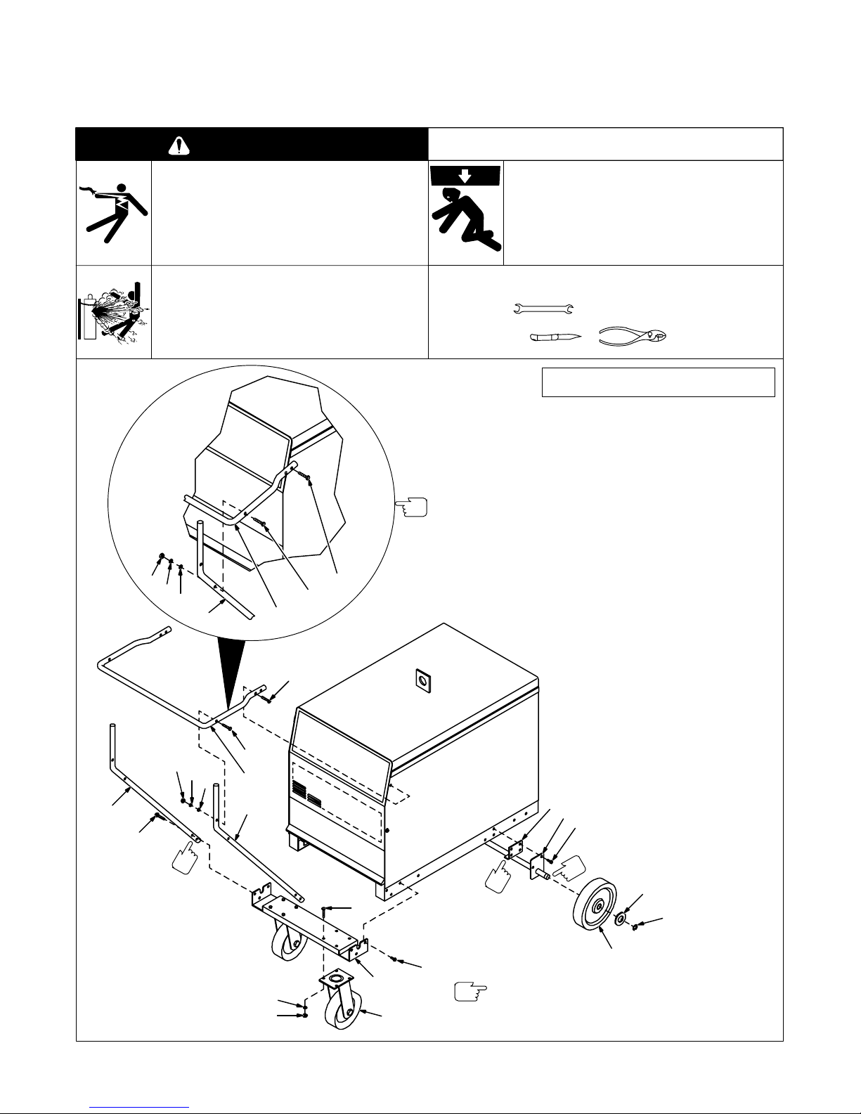
WARNING
ELECTRIC SHOCK can kill.
• Do not touch live electrical parts.
• Turn Off welding power source and input disconnect
device.
• Disconnect input power conductors from
deenergized supply BEFORE moving welding
power source.
CYLINDERS can explode if damaged.
• Keep cylinders away from welding and other
electrical circuits.
• Never touch cylinder with welding electrode.
• Always secure cylinder to running gear, wall, or
other stationary support.
1
2
3
4
5
7
7
6
For more weld cable
wraps around handle,
install handle in this
position.
FALLING EQUIPMENT can cause injury
and damage.
• Use proper equipment to lift unit.
• Use lifting forks long enough to extend out opposite
side of base.
• Do not put any body part under unit while lifting.
Tools Needed:
3/8, 7/16, 9/16, 5/8 in
Part
Item
No.
No.
1 +601 865 Nut, 1/4-20 (2)
2 +602 207 Washer, 1/4 lock (2)
3 +602 241 Washer, 1/4 flat (2)
4 +168 342 Upright Handle (2)
5 +168 341 Front Handle (1)
6 +098 877 Screw, 1/4-20 x 2-1/4 (2)
7 +049 966 Screw, 1/4-20 x 1-1/2 (6)
8 163 444 Shim (2)
9 163 446 Axle (1)
10 604 224 Screw, 1/4-20 x 3/4 (6)
11 602 250 Washer, 13/16 flat (2)
12 121 614 Retaining Ring (2)
13 163 463 Wheel, 10 in (2)
14 601 965 Screw, 3/8-16 x 1 (8)
15 163 442 Caster Mounting Bracket (1)
16 168 247 Caster (2)
17 601 872 Nut, 3/8-16 (8)
18 602 213 Washer , 3/8 lock (8)
+These it e m s a r e c o m m o n t o K i t N os. 042 886
and 043 055.
Be sure to provide Model when ordering
replacement parts.
Description (Qty)
miscwarn1.1 5/93
1
2
4
7
When installing Weld Cable
Holder Kit 043 055, use
same holes in welding power source that a r e used to install Three-Phase Running
Gear handle.
6
5
3
4
18
17
Figure 1. Installing Three-Phase Running Gear
14
15
16
Shim (8) is installed as a
spacer when cylinder
rack is not used.
10
When installing running gear and cylinder rack at the
same time, install axle according to Figure 2 or Figure 4.
8
9
10
Remove paint from axle grooves (9)
before installing retaining rings (12).
11
12
13
ST-800 213-B

Connect primary power cord
to welding power source before installing cylinder rack.
Installing mounting brackets and axle.
1
4
Installing cylinder rack and wheels
12
11
1 Welding Power Source
2 Mounting Bracket
Use matching holes on welding
power source base to install mounting brackets.
3 Axle (Supplied With Running
Gear)
Install axle to mounting brackets
(2).
2
3
5
6
7
8
4 Support Bracket
5 Cylinder Rack Assembly
Install support bracket to cylinder
rack assembly.
Remove the three screws from the
top rear of the welding power
source cover.
Secure cylinder rack assembly to
mounting brackets (2).
Secure support bracket to welding
power source (1) with screws removed from top rear of cover.
6 Wheel (Supplied With
Running Gear)
7 Washer (Supplied With
Running Gear)
8 Retaining Ring
Install wheels to axle, and secure
with washers and retaining rings.
9 Weld Cable Guide
Install weld cable guides.
10 Spring Hook
Install spring hooks into hole that
will allow chains to be tightened as
tight as possible around gas cylinders. Secure cylinder with chains
as shown.
11 Safety Lock
12 Lift Lever
Push safety lock while turning lift le-
ver to raise or lower cylinder rack.
Keep a tight grip on lever when raising and lowering rack loaded with a
cylinder as lever is under tension.
Keep body parts out from under
rack while raising and lowering
rack.
See Parts List for hardware sizes
used in this installation.
Installing weld cable guides and spring hooks,
Figure 2. Installing And Operating The Cylinder Rack/Lift
OM-687 Page 2
and operating the lift rack.
10
9
ST-800 656-A / Ref. S-170 364
 Loading...