

Page 1
~:~
r
~~jp~y
II
\\i\
OWN
ERS
MANUAL
MODEL
Voltage
Interface
Control
MILLER
ELECTRIC
MFG.
CO.
718S.BOUNDS
ST.
P.O.
Box
1079
APPLETON,WI
54912
USA
ADDITIONAL
COPY
PRICE
20
CENTS
.~
...__-
~.
.~...
-
-
~
_t__~__
-
-...
October
1981
FORM:
OM-868
1
I
U
NWSA
CODE
NO.
4579
PRINTED
IN
U.S.A.
Page 2
SECTION
1
-
INTRODUCTION
i-i.
GENERAL
INFORMATION
AND
SAFETY
A.
General
Information
presented
in
this
manual
and
on
various
labels,
tags,
and
plates
provided
on
the
unit
pertains
to
equipment
design,
installation,
operation,
maintenance,
end
troubleshooting
which
should
be
read,
understood,
and
followed
for
the
safe
and
effective
use
of
this
equip
ment.
B.
Safety
The
installation,
operation,
maintenance,
and
troubleshooting
of
arc
welding
equipment
requires
practices
and
procedures
which
ensure
personal
safety
and
the
safety
of
others.
Therefore,
this
equipment
is
to
be
installed,
operated,
and
maintained
only
by
qualified
persons
in
accordance
with
this
manual
and
all
ap
plicable
codes
such
as,
but
not
limited
to,
those
listed
at
the
end
of
Section
1
-
Safety
Rules
For
Operation
Of
Arc
Welding
Power
Sourceinthe
welding
power
source
Owners
Manual.
Safety
instructions
specifically
pertaining
to
this
unit
ap
pear
throughout
this
manual
highlighted
by
the
signal
words
~I~1:ikIl~ci
and
fs~tUII.J~I
which
identify
different
levels
of
hazard.
il~.1
~
II
~
statements
include
installation,
operating,
and
maintenance
proceduresorpractices
which
if
not
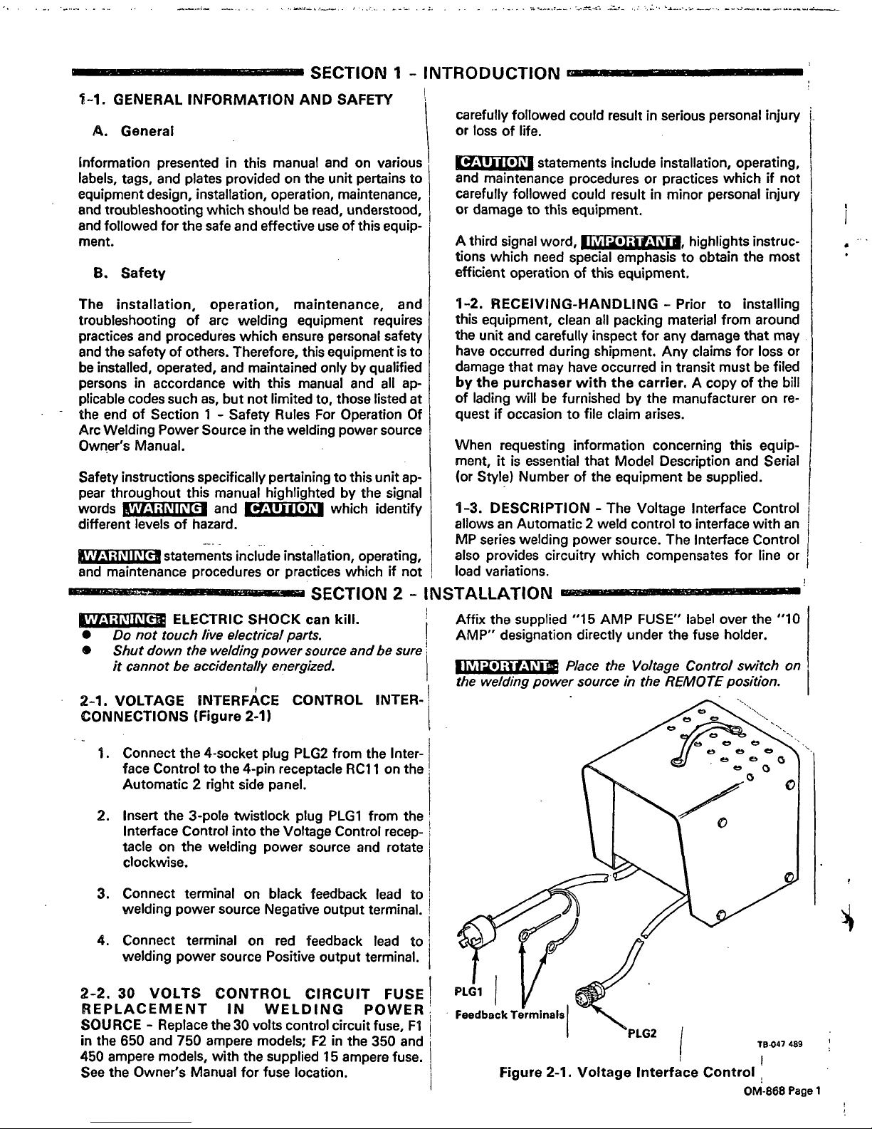
1.
Connect
the
4-socket
plug
PLG2
from
the
Inter
face
Control
to
the
4-pin receptacle
RC1
1
on
the
Automatic
2
right
side
panel.
2.
Insert
the
3-pole
twistlock
plug
PLG1
from
the
Interface
Control
into
the
Voltage
Control
recep
tacle
on
the
welding
power
source
and
rotate
clockwise.
3.
Connect
terminal
on
black
feedback
lead
to
welding
power
source
Negative
output
terminal.
4.
Connect
terminal
on
red
feedback
lead
to
welding
power
source
Positive
output
terminal.
2-2.
30
VOLTS
CONTROL
CIRCUIT
FUSE
REPLACEMENT
IN
WELDING
POWER
SOURCE
-
Replace
the
30
volts
control
circuit
fuse,
Fl
in
the
650
and
750
ampere
models;
F2
in
the
350
and
450
ampere
models,
with
the
supplied
15
ampere
fuse.
See
the
Owners
Manual
for
fuse
location.
carefully
followed
could
resultinserious
persona!
injury
or
tossoflife.
statements
include
installation,
operating,
and
maintenance
procedures
or
practices
which
if
not
carefully
followed
could
resultinminor
personal
injury
or
damage
to
this
equipment.
IMPORTANT
A
third
signal
word,
______________,
highlights
instruc
tions
which
need
special
emphasis
to
obtain
the
most
efficient
operation
of
this
equipment.
1-2.
RECEIVING-HANDLING
-
Prior
to
installing
this
equipment,
clean
all
packing
material
from
around
the
unit
and
carefully
inspect
for
any
damage
that
may
have
occurred
during
shipment.
Any
claims
for
loss
or
damage
that
may
have
occurred
in
transit
must
be
filed
by
the
purchaser
with
the
carrier.
A
copy
of
the
bill
of
lading
will
be
furnished
by
the
manufacturer
on
re
quest
if
occasion
to
file
claim
arises.
When
requesting
information
concerning
this
equip
ment,
itisessential
that
Model
Description
and
Serial
(or
Style)
Number
of
the
equipmentbesupplied.
1-3.
DESCRIPTION
-
The
Voltage
Interface
Control
allows
an
Automatic
2
weld
control
to
interface
with
an
MP
series
welding
power
source.
The
Interface
Control
also
provides
circuitry
which
compensates
for
line
or
load
variations.
CAUTION
WARNING~:
SECTION
2
-
INSTALLATION
____
ELECTRIC
SHOCK
can
kill.
Do
not
touch
live
electrical
parts.
Shut
down
the
welding
power
source
and
be
sure
it
cannot
be
accidentally
energized.
2-1.
VOLTAGE
INTERFACE
CONTROL
INTER
CONNECTIONS
(Figure
2-1)
Affix
the
supplied
15
AMP
FUSE
label
over
the
10
AMP
designation
directly
under
the
fuse
holder.
II
~il
~)
~
f..t~I
~
P/ace
the
Voltage
Control
switch
on
the
welding
power
source
in
the
REMOTE
position.
PLG1
LG2
T8047
489
Figure
2-1.
Voltage
Interface
Control
OM-868
Page
1
Page 3
Page2
T
(AA)
5-ORN
G~QN
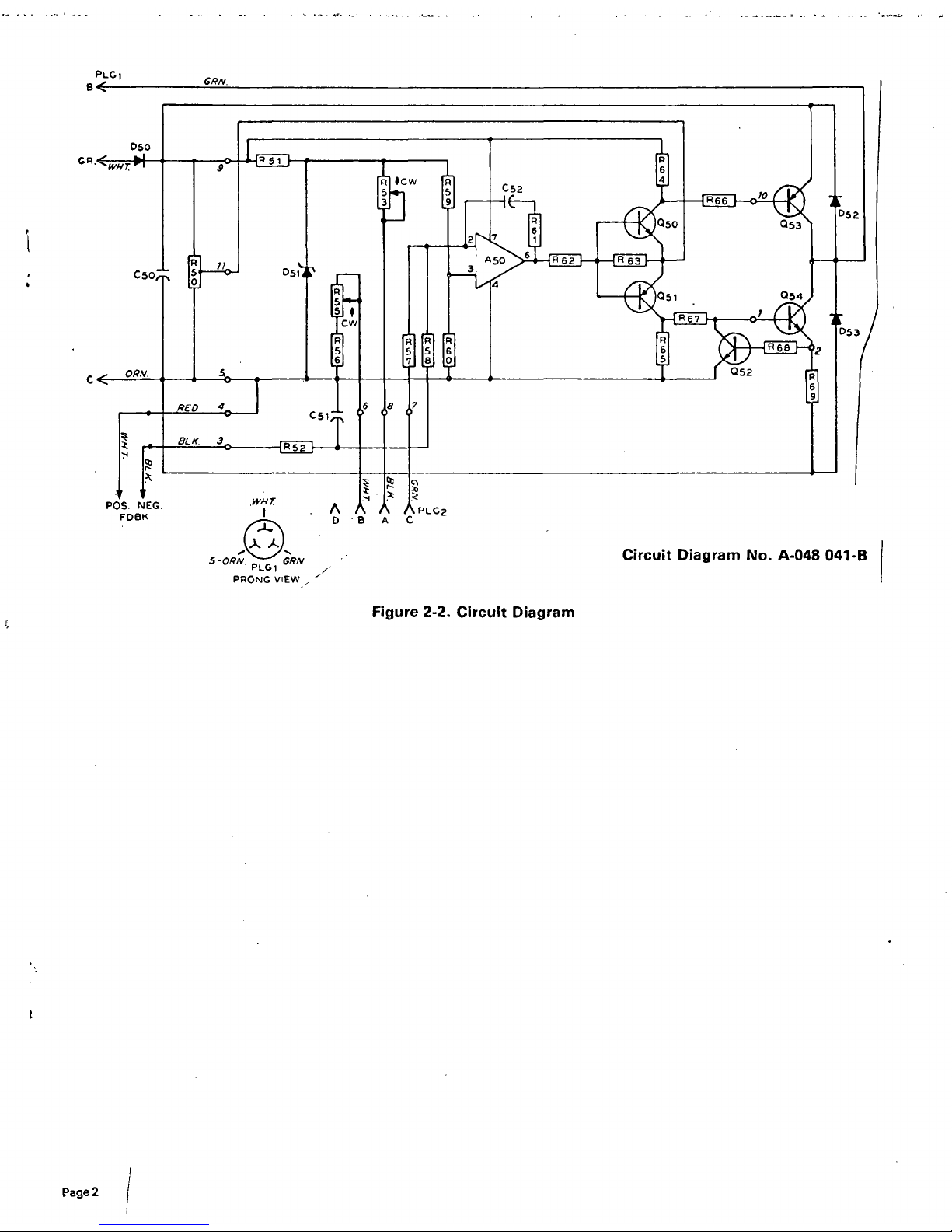
Circuit
Diagram
No.
A-048
041-B
PLCI
PRONG
VIEW
Figure
2-2.
Circuit
Diagram
Page 4

Page 5

MODEL
Voltage
Interface
Control
.-
.-~.-.
-~.
_~.._:___..
--.----
October
1981
FORM:
OM-868
PARTS
LOST
Page 6

S...
.
ai,.eae._.
~
._,..
..
.~s
.a..
jr
...
l
.
...
&
.
a
-
-
-
-v
s.
an
....
~
.a
a
~
-
1~
Figure
A
-
Complete
Assembly
It
it
0
0
1
TD-047
550
&
I
OM-868
Page
1
Page 7

Item
Dia.
Part
No.
Mkgs.
No.
Description
Quantity
Figure
A
Complete
Assembly
1
006
535
RECTIFIER,
silicon
diode
(consisting
of)
1
2
D50
037
952
.
DIODE,
rectifier
15
amp
200
volts
straight
polarity
1
3
006
428
.
BRACKET,
mounting
-
heat
sink
1
4
006
534
AMPLIFIER,
power
(consisting
of)
1
5
Q53
007
716
.TRANSISTOR,3OamplOOvoItsPNP
1
6
Q54
007
715
.TRANSISTOR,3Oamp9OvoItsNPN
1
7
006
425
.
HEAT
SINK,
diode
1
8
D53
037
952
.
DIODE,
rectifier
15
amp
200
volts
straight
polarity
1
9
R69
006429
.RESISTOR,5watt0.i
ohm
1
10
D52
037
451
.
DIODE,
rectifier
12
amp
200
volts
reverse
polarity
1
11
073
756
.
STAND-OFF,
No.
6-32
x
5/8
long
1/4
hex
4
12
601
242
.
INSULATOR,
washer
-
heat
sink
1
13
019
677
HANDLE,
door-
pull
1
14
021
475
WRAPPER
1
15
006
427
BRACKET,
mounting-circuit
card
1
16
007
156
CIRCUIT
CARD
(consisting
of)
1
A50
008
971
.INTEGRATED
CIRCUIT,
operational
amplifier
1
C51
031
721
.
CAPACITOR,
mylar
0.22
uf
200
voltsdc
1
C52
031
693~
.
CAPACITOR,
mylar
0.33
uf75voltsdc
1
D51
037
449
.
DIODE,
zener
15
volts
1
watt
straight
polarity
1
Q50,52
039
353
.
TRANSISTOR,
4
amp
40
volts
NPN
2
Q51
039
354
.
TRANSISTOR,
4
amp
40
volts
PNP
1
R51
000
039
.
RESISTOR,
carbon
2
watt
680
ohm
1
R52,58
605
979
.
RESISTOR,
metal
film
0.25
watt
15K
ohm
2
R53,55
006 424
.
POTENTIOMETER,
cermet
1
turn
5
watt
2K
ohm
2
R56
035
825
.
RESISTOR,
carbon
film
0.25
watt
1K
ohm
1
R57,60
605
978
.
RESISTOR,
metal
film
0.25
watt2.74K
ohm
2
R59 000 035
.
RESISTOR,
metalfilrn0.5watt6.8K
ohm
1
R61
035
884
.
RESISTOR,
carbon
film
0.25
watt
lOOK
ohm
1
R62
030
033
.
RESISTOR,
carbon
0.5
watt
470
ohm
1
R63
030
038
.
RESISTOR,
carbon
0.5
watt
220
ohm
1
R64,65
030
024
.
RESISTOR,
carbon
0.5
watt
1000
ohm
1
R66,67
030
839
.
RESISTOR,
WWfixed
5
watt
220
ohm
2
R68
030
937
.
RESISTOR,
carbon
0.5
watt
10
ohm
1
1
,2T
000
059
.
BLOCK,
terminal
5
amp
6
pole
2
17
R50
006
532
RESISTOR,
WWadj50watt5ohmw/Ieads
1
18
084
804
CORD,
voltage
-
control
(consisting
of)
1
19
007
826
.
CORD,
No.18
3/c
(order
byft)
lift
20
039
828
.
CLAMP,
cable
1
21
047
544
.
PLUG,
4
socket
MS-3106A-14S-2SX
1
22
048
298
CASE
SECTION,
base/front/rear
1
23
010
610
CONNECTOR,
clamp
-
cable
1
24
010
659
CONNECTOR,
clamp-cable3/8
inch90deg
1
25
006
530
CABLE,
power
(consisting
of)
1
26
006
531
.
CABLE,
power
1
27
PLG1
605
797
.
CAP,
twistlock3P3W20
amp
125
volts
1
28
600
340
.
CORD,
No.
16
2/c
(order
by
ft)
4
ft
29
006
426
BRACKET,
mounting
-
capacitor
1
30
C50
031
728
CAPACITOR,
electrolytic
9000
uf35voltsdc
1
*027
419
FUSE,
ceramic
15
amp
250
volts
(loose
item)
1
013
312
LABEL,
use
15
amp
fuse
*Recommended
Spare
Parts.
BE
SURE
TO
PROVIDE
MODEL
AND
SERIAL
NUMBERS
WHEN
ORDERING
REPLACEMENT
PARTS.
OM-868
Page
2
Page 8

 Loading...