

Miller Electric 350, VERNIER RANGE CONTROL, MR-5/ARC PAK 350 Owner's Manual
Y8y7?~i
Read
and
understand
the entire
contents
of both this
manual
and
the
power
source
manual
used
with
this unit,
with
special
eutiphasis
on
the safety
material
throughout
both
manuals,
before
installing,
operating,
or maintaining this
equipment. This
unit
and
these
instructions
are
for
use
only by
persons
trained
and
experienced
in the
safe
operation of welding
equipment.Donot allow
untrained
personstoinstall,
operate,
or maintain
this unit.
Contact
your
distributorifyoudonot
fully
understand these
instructions.
OWN
ER’S
MANUAL
Effe~ti.EWith
SanEIFic...H1:33:~’
I
MODEL
MR-5/ARC
PAK
TM
350
COMPUTER
INTERFACE
GAS/CURRENT
SENSING
CONTROL
+5
millER
MILLER
ELECTRIC
MFG.
Co.
718SBOUNDS
ST,P0
Box
1079
APPLETON,WI54912
USA
ADDITIONAL
COPY
PRICE95CENTS
NWSA
CODE
NO.
4579
PRINTEDINU S
A
IMPORTANT:
LIMITED
WARRANTY
4;
4;
4;
4!
4;
4;
~Ji
4~
1.
2.
<
3.
4.
~
7.
This
warranty
supersedes
all
previous MILLER
warranties
andisexclusive
with no
other
guaranteesorwarranties
expressedorimplied
LIMITED
WARRANTY
Subjecttothe
terms
and
condi
-
tions
hereof,
Miller
Electric
Mfg.
Co.,
Appleton,
Wisconsin
warrants to
its
Distributor/Dealer
that
all
new
and unused
Equipment
furnishedbyMillerisfree
from defectinworkman
-
ship
and
materialasof
the
time
and
placeofdeliverybyMiller.
No
warrantyismadebyMiller
with
respecttoengines,
trade
accessories
or other
items
manufacturedbyothers.
Such
engines,
trade
accessories
and
other
items
are
sold
subject
to
the
warrantiesoftheir
respective
manufacturers,ifany . All
engines
are
warranted
bytheir
manufacturer
for
one
year
from
date of
original
purchase,
except
Tecumseh
engines
which
haveatwo
year
warranty.
Exceptasspecified
below,
Miller’s warranty
does
not
apply
to
components
having normal
useful
lifeofless
than
one
Ill
year, suchasspot
welder
tips,
relay
and
contactor points,
MILLERMATIC
parts
that
comeincontact with the
welding
wire
including
nozzles
and
nozzle
insulators
where failure
does
not
result
from defectinworkmanshipormaterial.
Miller
shallberequired
to honor warranty
claimsonwar
-
ranted Equipmentinthe
eventoffailure
resulting
fromadefect
within
the
following
periods
from
the
dateofdeliveryofEquip
-
ment to
the
original
user:
In
the
caseofMiller’s
breachofwarrantyorany
other
duty
with
respecttothe
qualityofany
goods,
the exclusive remedies
therefore
shall
be,atMiller’s
option
(11
repairor121
replacement
or,
where
authorizedinwritingbyMillerinappropriate
cases,
(3)
the
reasonable
costofrepairorreplacementatan
authorized
Miller
service
stationor14)
paymentofor
credit for
the purchase
price
(less
reasonable
depreciation
based
upon
actual
usel
upon
returnofthe
goodsatCustomer’s
risk
and
expense.
MILLER’s
optionofrepairorreplacement
willbeFOB.,
Factory,
at
Appleton,
Wisconsin,orFOB.,ata
MILLER authorized
service
facility,
therefore,nocompensation
for
transportation
costs
of
any
kind
willbeallowed.
Upon
receiptofnoticeofapparent
defectorfailure,
Miller
shall
instruct
the
claimantonthe
warranty
claim
procedures
to be
followed.
ANY
EXPRESS
WARRANTY
NOT
PROVIDED
HEREIN
AND
ANY
IMPLIED
WARRANTY,
GUARANTYORREPRESENTA
-
•flONASTO
PERFORMANCE,
AND ANY
REMEDY
FOR
BREACHOFCONTRACT
WHICH,
BUT FOR
THIS PROVISION,
MIGHT
ARISEBYIMPLICATION,
OPERATIONOFLAW,
CUSTOMOFTRADEORCOURSEOFDEALING, INCLUDING
ANY
IMPLIED
WARRANTYOFMERCHANTABILITYOROF
FITNESS FOR
PARTICULAR
PURPOSE,
WITH
RESPECT
TO
ANY
AND ALL
EQUIPMENT
FURNISHEDBYMILLERISEX
-
CLUDED
AND
DISCLAIMEDBYMILLER.
EXCEPT
AS
EXPRESSLY
PROVIDED BY
MILLER
IN
WRITING,
MILLER
PRODUCTS
ARE
INTENDED
FOR
ULTIMATE
PURCHASE
BY
COMMERCIAL/INDUSTRIAL
USERS
AND
FOR
OPERATIONBYPERSONS
TRAINED
AND
EXPERIENCEDINTHE USE
AND
MAINTENANCE
OF
WELDING
EQUIPMENT
AND NOT
FOR
CONSUMERS
OR
CONSUMER USE. MILLER’S
WARRANTIESDONOT
EXTEND
TO,
AND
NO
RESELLERISAUTHORIZEDTOEXTEND
MILLER’S
WARRANTIES
TO,
ANY
CONSUMER.
Arc
welders,
power
sources,
robots,
and
components.1
year
Load
banks
1
year
Original
main
power
rectifiers
3
years
Ilabor-1
year
onlyl
All
welding guns,
feeder/guns
and
plasma
torches...90days
All
other
Millermatic
Feeders
1
year
Replacementorrepair
parts,
exclusive
oflabor..60days
Batteries
6
months
provided
that
Millerisnotifiedinwriting
within
thirty
1301
days
of
the
date
of such
failure.
Asamatterofgeneral
policy
only,
Miller
may
honor
claims
submittedbythe
original
user
within
the
foregoing
periods.
EFFECTIVE:
OCTOBER1,1986
ERRATA
SHEET
AMENDMENTTOSECTION2—INSTALLATION
A
WARNING: ELECTRIC
SHOCK
can
kill.
0
Do
not
touch
live
electrical
parts.
A.
CVICC
Connections
A
1.
Locate
terminal
Strip
2T.
May
31,1990
~OM.882j
After
this
manual
was
printed,
refinementsInequipment
design
occurred.
This
sheet
lists
exceptions
to
data
appearing
laterinthis
manual.
IMPORTANT:
A25ft.
(8m)
interconnecting
cord
withafive-pin
Amphenoiplugissupplied
with
this
unit
butisnot
used
in
this
installation. Retain
cord
for
future
use.
Add the
foliowing
IMPORTANT
blocktothe
end of Section
2-3A.
COMPUTER
INTERFACE-WELDING
POWER
SOURCE
CONNECTIONS: Wire
Stick Sensing
Connections
IMPORTANT:
If dc
electrode
negative
weldingisdesired,
reverse connections so
the
lead
with
ring
terminal
is
connectedtothe
negative
weld
output
terminal
and
the
lead
withaclampisconnectedtothe
positive
weld
output
terminal.
Amend
Section
2-3C.
COMPUTER
INTERFACE-WELDING
POWER
SOURCE
CONNECTiONS:
115
Volts
AC/Contactor Control
Connection
IMPORTANT:
Cords
are
supplied
that
may
not
be used
in this
installation.
Match
cordtowelding
power
source
and
computer
interface
available.
1.
Align
keyways,
insert
4-socket
Amp
plug
into
matching
receptacleoncomputer
interface,
and rotate
threaded
collar
fully clockwise.
2.
Align
keyway,
insert
14-pin
Amphenol
plug
into
matching
receptacleonwelding
power
source,
and
rotate
threaded
collar fully
clockwise.
3.
Place
appropriate
remote control switch(es)onthe
welding
power
sourceinthe
proper
position
for
useofa
remote control
device.
Amend
Section 2-5.
COMPUTER
INTERFACE
TERMINAL
STRIP
CONNECTIONS
0
Shut
down unit,
welding
powersource, and
robot,
and
disconnect
input
power
employing
locko
ut/tag
-
ging
procedures
before
making
interconnections.
Lockout/tagging
procedures
consistofpadlocking
line
disconnect
switchinopen
position, removing fuses
from
fuse box,orshutting
off
and
red-tagging
circuit
breakerorother
disconnecting
device.
There
are
several
terminal
strips
inside the
computer
interface
for
control
connections. Remove
unit
top
cover,
loosen
screwsonstrain
reliefonunit
rear
panelifnecessary,
and
locate
appropriate terminal
strip
for
connections.
Tighten
screwsonstrain
reliefifnecessary,
and reinstall
top
cover
when
procedureisfinished.
WARNING:
Read
and
follow
safety
informationatbeginning of Section
2-5
before
proceeding.
2.
ForCCoperation,
remove
jumper
link
between
terminalEandFon
2T.
IMPORTANT:
The
Inductance controlisdisabled
when operatingintheCC(constant
current)
mode.

B.
ARC
FAILURE
Light
Connections
(Figure 2-4)
A
WARNING:
Read
and
follow safety Informationatbeginning
of Section
2-5
before
proceeding.
The ARC FAILURE
light
orlthe
computerinterface front panelisturnedon
and
off
by a
signalfromthe
robot control
unit.
Locate
supplied
lengthof18
gauge/2-conductor cord
for
this
connection,
and
proceedasfollows:
1.
For
robot control
units
withnoother
connectionsatjig
terminal
strip
2:
a.
Open
robot control
unit
door,
and
locate
jig
terminal
strip
2.
b.
Route
cord under
cross member
below
door.
c.
Make cord connectionstoterminal
strip
common and
the Weld Alarm
terminal.
d.
Close
robot control
unit
door,
and
route cord
through strain
relief on
rear
panelofcomputer
interface.
e.
Connect
cordto2TF
and
2TG.
2.
For
robot control
Units
when
115or24 vac,or24
vdcisusedatjig terminal
strip
2T:
a.
Obtaina115or24
vac,or24
Vdc
isolation
relay,
and install
into
jig
interface.
b.
Open
robot control
unit
door,
and
locate
jig
terminal
strip
2.
c. Route
customer supplied18gauge/2-conductor cord under
cross member
below
door.
d.
Make
cord connectionstoterminal
strip
common
and
the
Weld Alarm
terminal.
e.
Close
robot control
unit
door,
and
route
cordtojig
interface.
f.
Connect
cordtoisolation
relay
coil
and
voltage source.
g.
Cut
off
terminals from
one end of
supplied18gauge/2-conductor
cord,
and
install terminalstoconnect
to
contactsonisolation
relay.
h.
Connect
one end of
cordtoa
setofnormally-open
contactsonisolation
relay.
i.
Route cord
through strain
relief on
rear
panelofcomputer interface.
j.
Connect
cordto2TF
and
2TG.
OM-882 Page
2
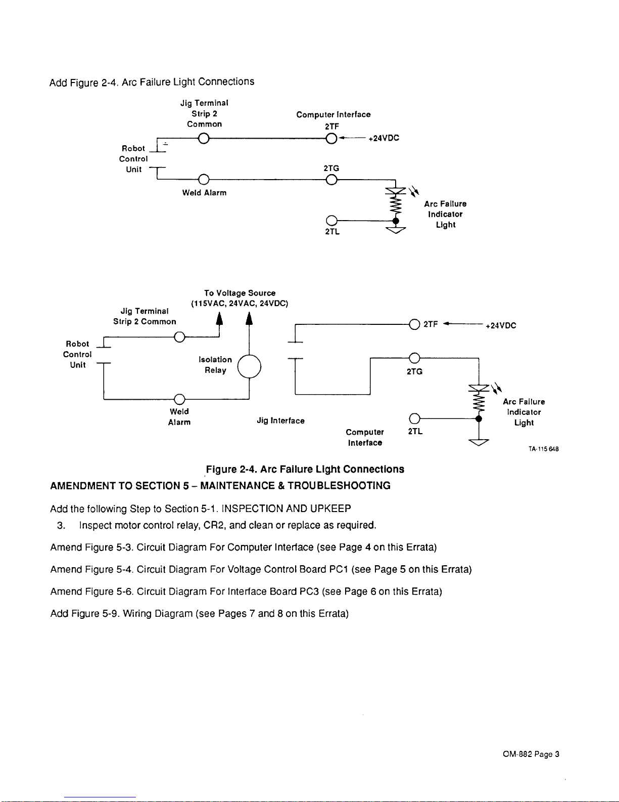
Add
Figure
2-4.
Arc
Failure Light
Connections
Jig
Terminal
Strip
2
Common
Robot
control
Unit
weld
Alarm
Robot
Control
Unit
Computer
Interface
2TF
+24VDC
2TG
2TL
Arc
Failure
Indicator
Light
To Voltage
Source
(115VAC, 24VAC,
24VDC)
-rj 2TF ~—
Arc
Failure
Indicalor
Light
TA-il5
648
Figure
2-4. Arc
Failure
Light
Connections
AMENDMENTTOSECTION5-MAINTENANCE&TROUBLESHOOTING
Add the
following SteptoSection
5-1-INSPECTION
AND
UPKEEP
3.
Inspect
motor
control
relay,
CR2,
and
cleanorreplaceasrequired.
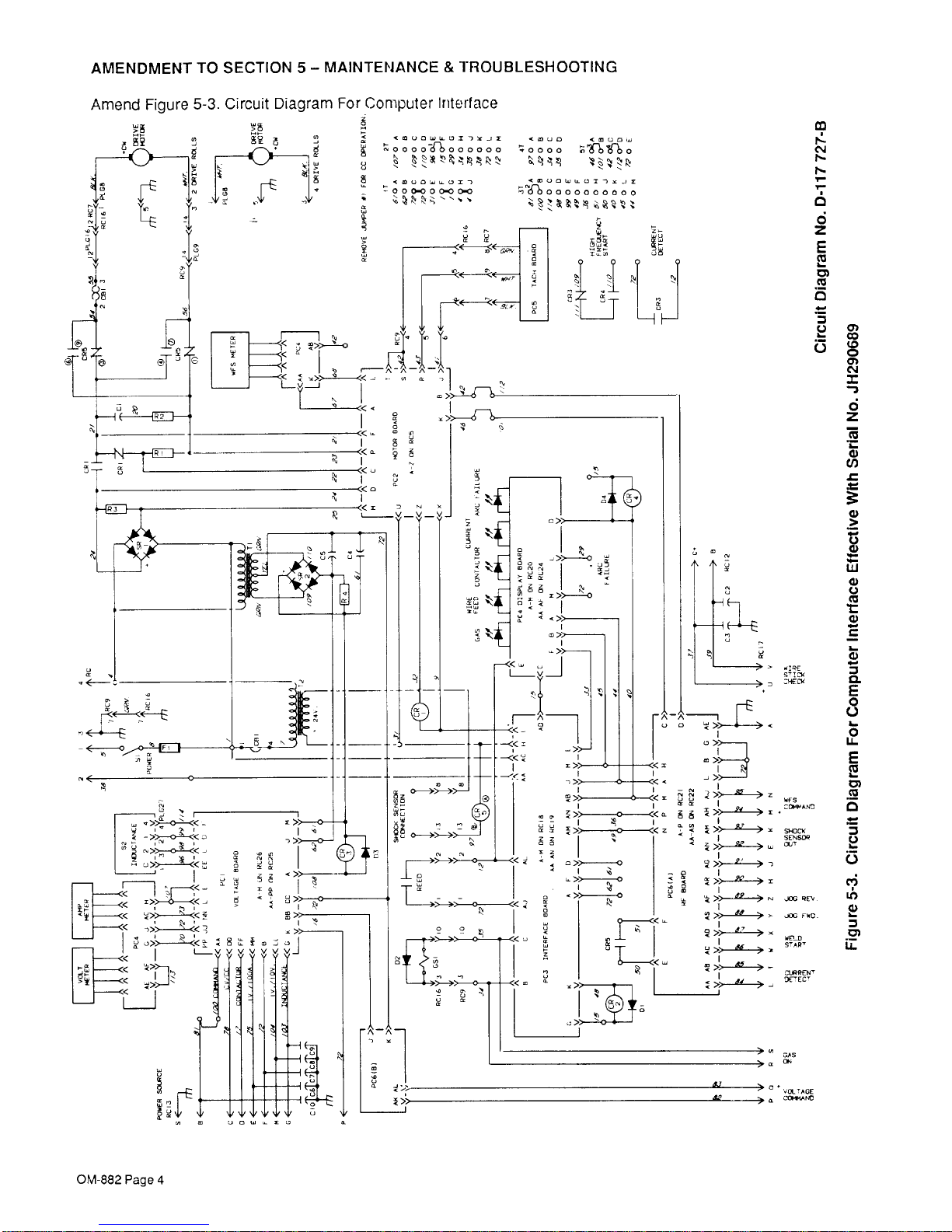
Amend
Figure
5-3.
Circuit
Diagram
For
Computer
Interface
(see
Page4on
this
Errata)
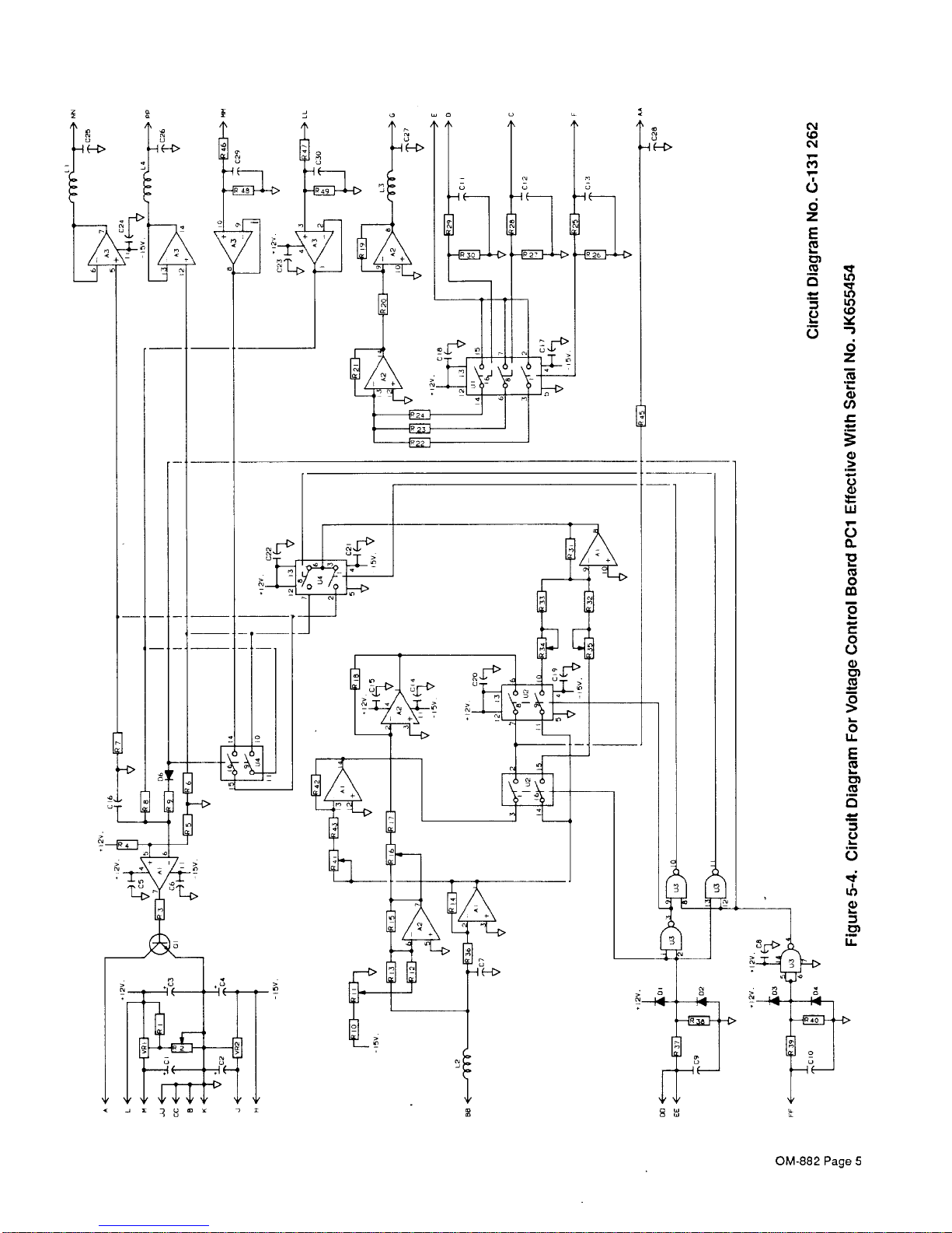
Amend
Figure
5-4.
Circuit
Diagram
For
Voltage
Control
Board
PCi
(see
Page5on
this
Errata)
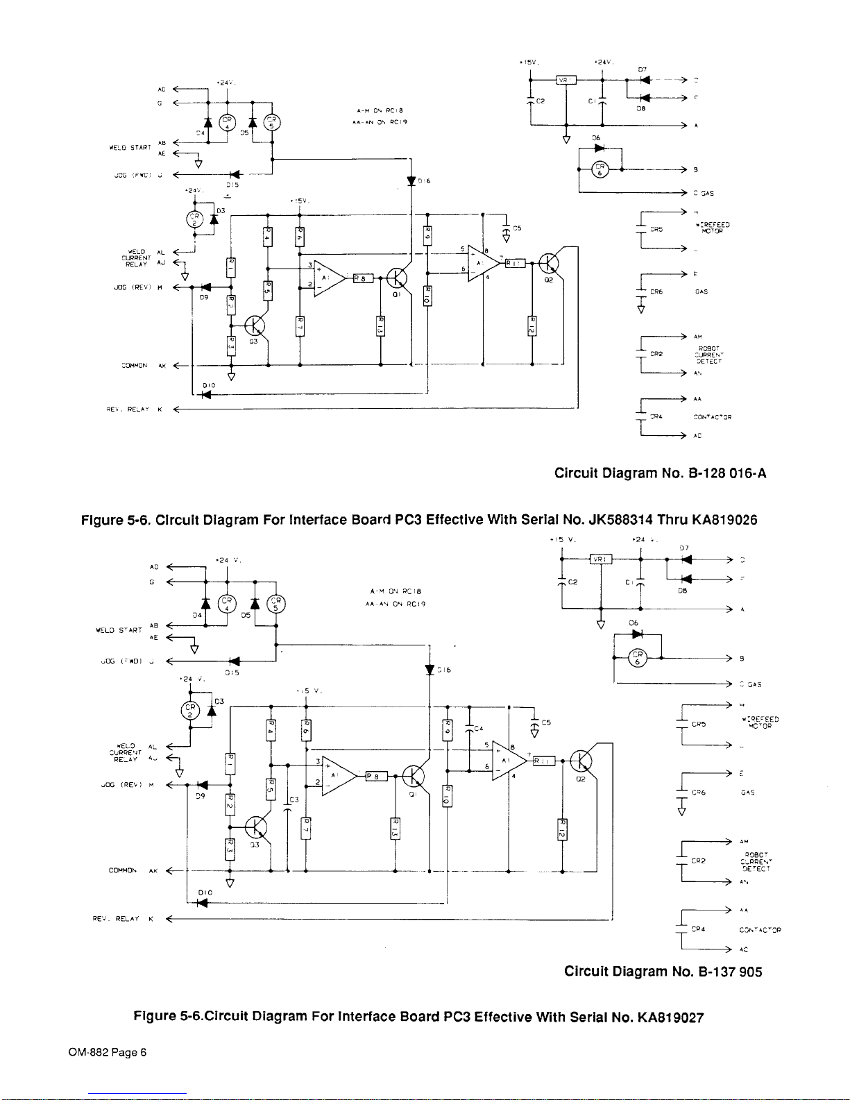
Amend
Figure
5-6.
Circuit Diagram
For
Interface
Board PC3 (see
Page6on
this
Errata)
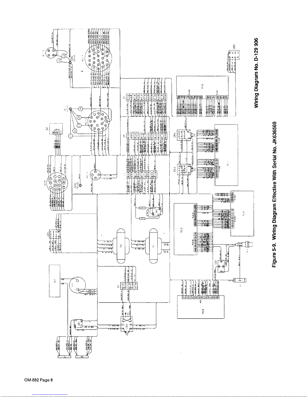
Add
Figure
5-9.
Wiring Diagram
(see
Pages7and8on
this
Errata)
Weld
Alarm
Jig
Interface
OM-882
Page
3
AMENDMENT
TO SECTION
5-MAINTENANCE&TROUBLESHOOTING
000
0~
000000
Amend
Figure
5-3.
Circuit
Diagram
For
Computer
Interface
U K U
k~,
~000
00
00 000
-
~
-,
C0CWL.~CI~N
=0CL,Lt,~tj7~~liU
C
K
-~
~
N
d
z
E
Cu
0
(3
N.FS
SN-CCN(
srNso~
JOG
~EV
~ ~
cc
to
0
C~J
6
z
w
U
0)
0)
U
0)
0)
0.
E
0
C.)
I
-
0
U
-
E
I
-
0)
0
I..
(3
0)
1~
ci
‘N
S~~CNN
9E’EC’
Ua’AGE
OM-882 Page
4
a
I
C.’J
to
C~4
1~
6
6
z
E
Cu
Cu
•~‘
to
o
.~
—
to
U,
o
(3-,
6
z
1~
0)
C/)
0)
0
0)
w
5
0.
•0
I-
Cu
0
3
0
C.)
0)
C)
Cu
3
I
-
0
IL
E
Cu
I-
C)
Cu
4
-
U
I-
(3
0)
C)
OM-882
Page
5
5V
,24V
AR
4ELD
START
AL
JOG
F~C
2
WELD
AL
~
CURRENT
RELA’
AJ
JOG
(RE.
A
RE..
RE.A’
4
06
CR
CR5
C ON-S
REFEEC
ACTOR
6050’
CJRRE’.’
CECXC
T
CR4
CON’N-C’CR
AC
Circuit
Diagram
No.
B-128
016-A
FIgure
5-6.
CIrcuit
Diagram
For
interface
Board
PC3
Effective
With
Serial
No.
JK588314
Thru KA819026
‘LO
A
‘24
Circuit
Diagram
C
SELFEC
045
AC’CR
C66
T
OR?
6080’
CLPRE
N
CE
CEO
C
CR4
0C7,’4C’CR
AC
No.
B-i37905
Figure 5-6.Circuit
Diagram
For
interface
Board
PC3
Effective
With
Serial
No. KABi
9027
.24
C.
CC
AC
6
~ELC
S’ART
AR
AE
UDO
(L(~fl(
—
RELO
AL
CURRENT
RELAY A.
406
(RE6I
A
C07R40N,
ALA
REV. RELAX
1<
06
CR
6
OM-882 Page
6
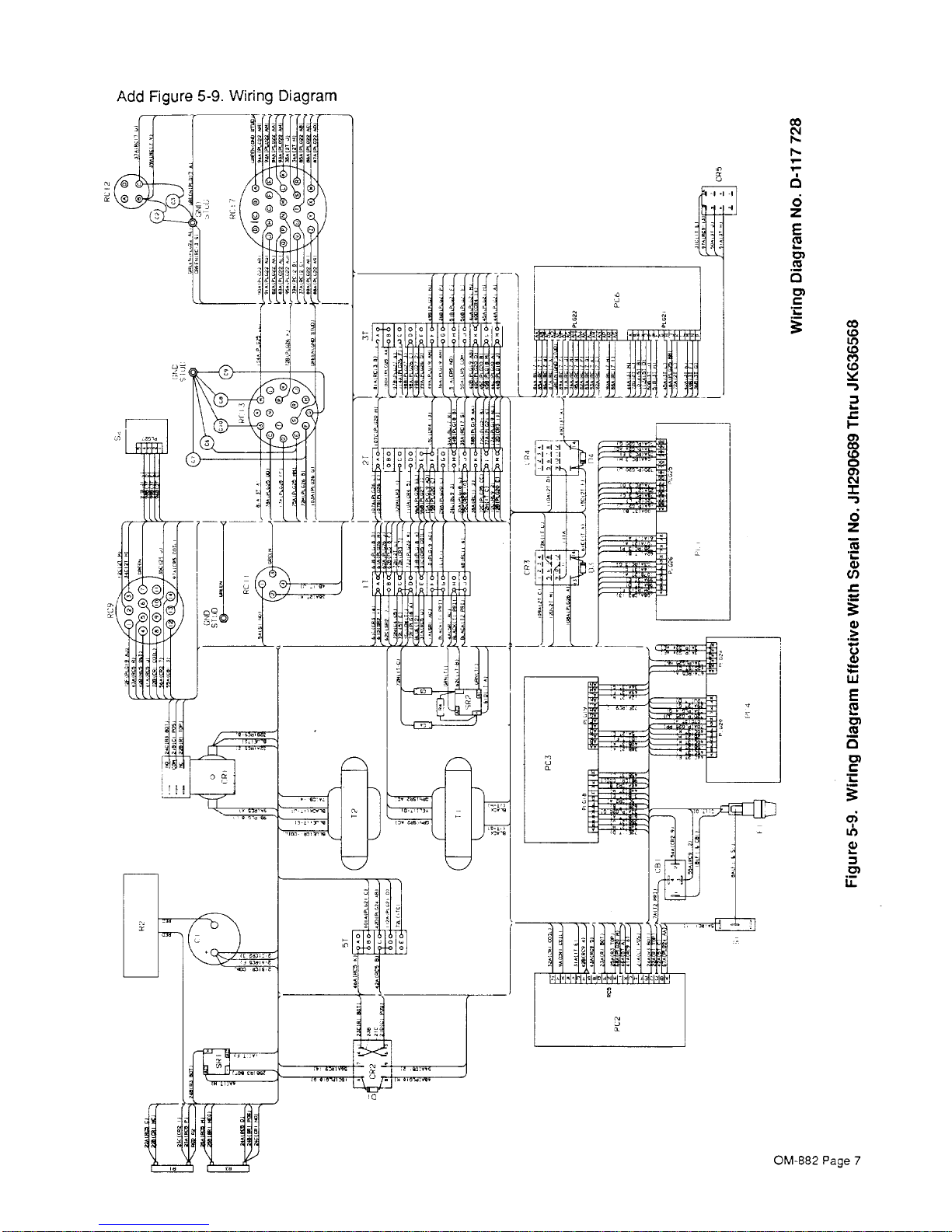
Add
Figure
5-9.
Wiring
Diagram
cc
r-.
I”
-
1~
‘N
0
6
z
E
Cu
C)
0
C)
cc
U,
to
to
1..
I
-
cc
to
0
c,,J
6
z
h..
0)
U)
0)
C.)
0)
w
E
Cu
I..
C)
Cu
0
C)
C
U,
0)
C)
ir
OM-882
Page
7
to
U,
to
to
6
2
I-
0)
U)
0)
0)
w
E
Cu
C)
0
C
0)
L..
c~J
1~
6
z
E
Cu
I-
C)
0
C
OM-e82 Page 8
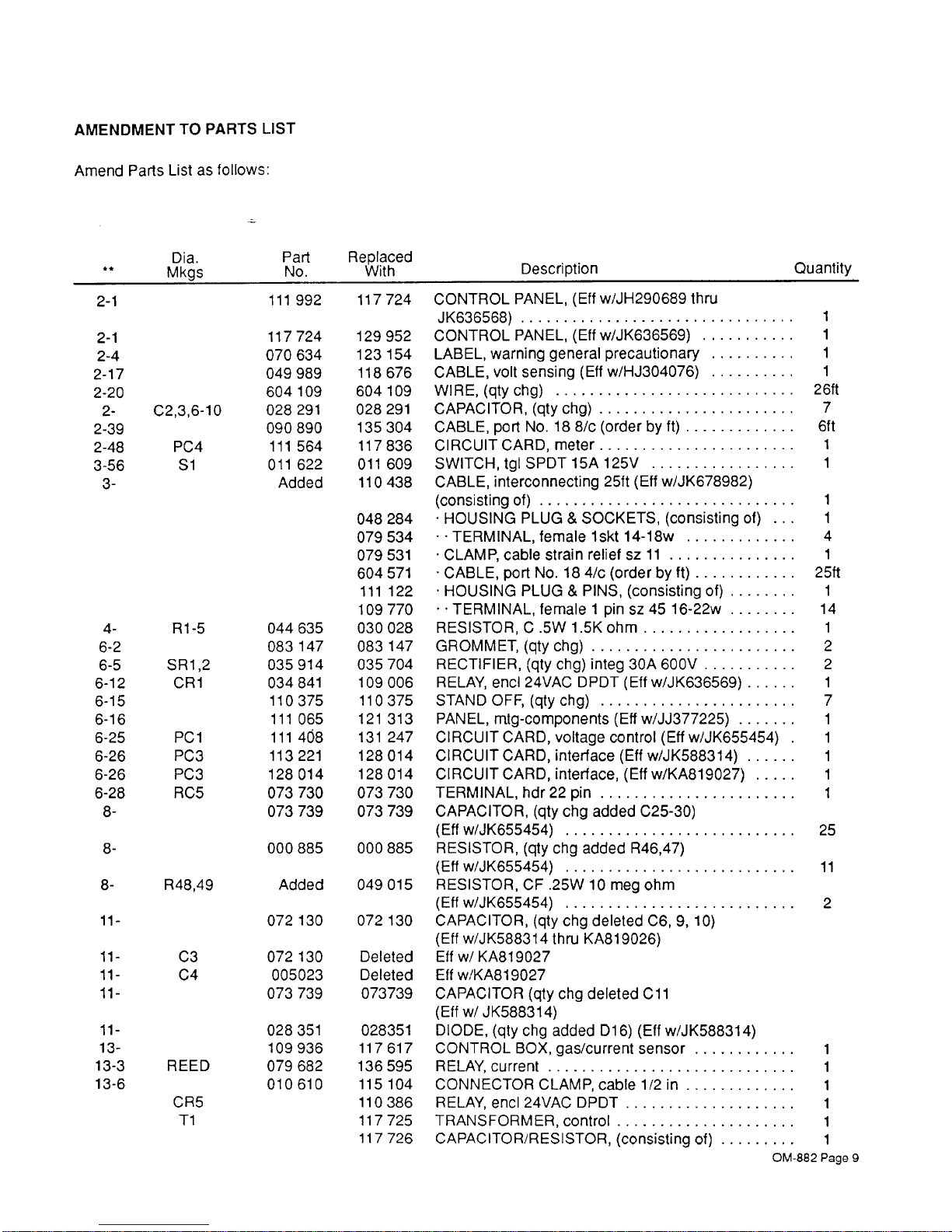
AMENDMENTTOPARTS
LIST
Amend
Parts
List
as follows:
Part
Replaced
No.
With
2-1
2-1
2-4
2-17
2-20
22-39
2-48
3-56
3-
4-
6-2
6-5
6-12
6-15
6-16
6-25
6-26
6-26
6-28
8-
C2,3,6-10
PC4
51
Ri-S
SR
1,2
CR1
PCi
PC3
PC3
RC5
8-
8- R48,49
11—
11—
11-
11-
11—
13-
13-3
13-6
C3
C4
REED
CR5
Ti
111
992
117
724
CONTROL
PANEL,
(Elf
w/JH290689
thru
JK636568)
117724
129
952
CONTROL
PANEL,
(Effw/JK636569)
070 634
123
154 LABEL,
warning general
precautionary
049 989
118
676
CABLE,
volt
sensing
(Eff
w/HJ304076)
604
109
604
109
WIRE,
(qty
chg)
028
291
028
291
CAPACITOR,
(qty
chg)
090 890
135
304
CABLE,
port
No.188/c
(orderbyft)
iii
564
117836
CIRCUITOARD,
meter
011
622
011
609
SWITCH,
tgl
SPDT
iSA
125V
Added
110
438
CABLE,
interconnecting
25ft
(Eff
w/JK678982)
(consisting
of)
048 284
HOUSING
PLUG&SOCKETS,
(consisting
of)
079 534
.
TERMINAL,
female
iskt
14-18w
079
531
CLAMP, cable
strain
reliefsz11
604
571
CABLE,
port
No.
184/c
(orderbyft)
iii
122.HOUSING
PLUG
&
PINS,
(consisting
of)
109 770
TERMINAL,
female1pinsz45
16-22w
044
635
030
028
RESISTOR,C.5W
1.5K
ohm
083
147
083
147
GROMMET,
(qty
chg)
035 914 035
704
RECTIFIER,
(qty
chg)
integ
30A
600V
034
841
109
006
RELAY,
end
24VAC
DPDT
(Effw/JK636569)
110375
110375
STANDOFF,
(qtychg)
111
065
121
313
PANEL,
rntg-components
(Elf
w/JJ377225)
111
408
131
247
CIRCUIT
CARD,
Voltage
control
(Effw/JK655454)
113 221
128 014
CIRCUIT
CARD, interface
(Effw/JK588314)
128014
128014 CIRCUITCARD,interface,
(Effw/KA819027)
073
730
073
730
TERMINAL,
hdr22pin
073 739 073
739
CAPACITOR,
(qty
chg
added C25-30)
(EU
w/JK655454)
000 885 000
88S
RESISTOR,
(qty
chg
added
R46,47)
(Elf
w/JK655454)
Added
049
015
RESISTOR,CF.25W10meg ohm
(Eff
w/JK655454)
072
130
072
130
CAPACITOR,
(qty
chg
deleted
C6,9,10)
(Elf
w/JK588314
thru KA819026)
072
130
Deleted
Elf
w/KA819027
005023 Deleted
Elf
w/KA819027
073
739
073739
CAPACITOR
(qty
chg
deleted
Cli
(Elfw/JK5883
14)
028
3S1
028351
DIODE, (qty
chg
added D16)
(Elf
w/JK588314)
109
936
117 617
CONTROL
BOX,
gas/current
sensor
079682
136
59S
RELAY,current
010
610
115
104
CONNECTOR
CLAMP, cable
1/2
in
110386 RELAY,encI24VACDPDT
117725
TRANSFORMER,control
117 726
CAPACITOR/RESISTOR,
(consisting
of)
OM-582
Page
9
Dia.
Mkgs
Description
Quantity
1
1
1
1
2
6ft
7
61
t
1
1
1
1
4
1
25ft
1
14
1
2
2
1
7
1
1
1
1
1
25
ii
2
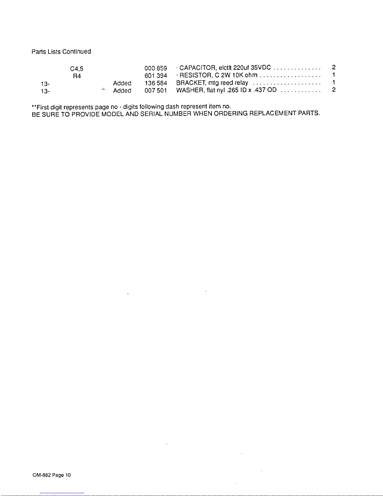
Parts
Lists Continued
000
859
601
394
Added
136584
Added
007501
•
CAPACITOR,
eIctlt
220uf 35VDC
2
•RESISTOR,C2WlOKohm
BRACKET,
mtg
reed
relay
1
WASHER,
flat
nyl
.265
ID x
.437 OD
2
~First
digit represents
page
no
-
digits following
dash
represent
item
no.
BE
SURETOPROVIDE MODEL
AND
SERIAL
NUMBER
WHEN
ORDERING REPLACEMENT
PARTS.
C4,S
R4
13-
13-
OM-882 Page
10
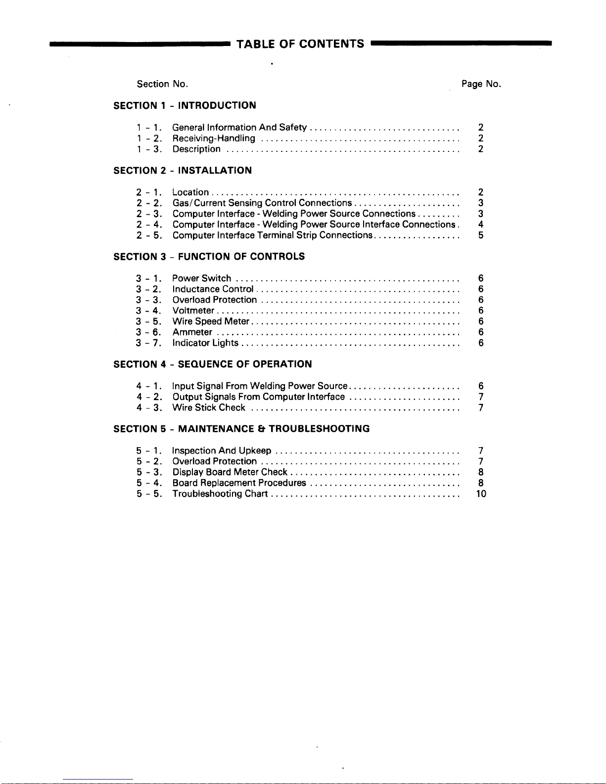
TABLE
OF
CONTENTS
Section
No.
Page
No.
SECTION
1-INTRODUCTION
1-1.
General
Information
And
Safety
2
1-2.
Receiving-Handling
2
I
-
3.
Description
2
SECTION
2-INSTALLATION
2-1.
Location
2
2-2.
Gas/Current
Sensing
Control
Connections
3
2-3.
Computer Interface-Welding
Power
Source
Connections
3
2-4.
Computer Interface-Welding
Power
Source Interface
Connections.
4
2-5.
Computer Interface Terminal
Strip
Connections
5
SECTION
3-FUNCTIONOFCONTROLS
3-1.
PowerSwitch
6
3-2.
Inductance
Control
6
3-3.
Overload
Protection
6
3-4.
Voltmeter
6
3-5.
WireSpeedMeter
6
3-6.
Ammeter
6
3
-
7.
Indicator
Lights
6
SECTION
4-SEQUENCEOFOPERATION
4-1.
input
Signal
From
Welding
Power
Source
6
4-2.
Output
Signals
From
Computer Interface
7
4-3.
Wire
Stick
Check
7
SECTION
5-MAINTENANCE8TROUBLESHOOTING
5-1.
Inspection
And
Upkeep
7
5-2.
Overload
Protection
7
5-3.
Display
Board
Meter
Check
8
5-4.
Board
Replacement
Procedures
8
5-5.
Troubleshooting
Chart
10
SECTION
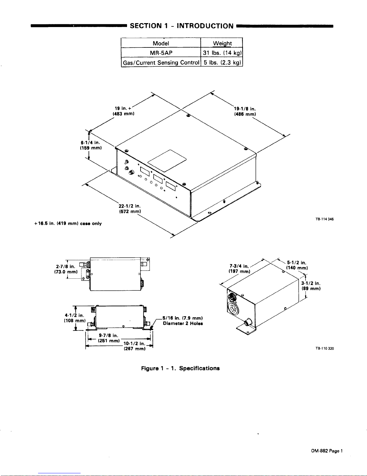
1-INTRODUCTION
Model
I-
MR-5AP
I
Gas/Current
Sensing
Weight
31
lbs.
(14
kg)
Control5lbs.
(2.3
kg)
+
16.5
in.
(419
minI
case only
2-7/8
in.
(73.0 minI
Figure
1-1.
Specifications
TB-i
14346
In.
mm)
16
in. (7.9
mm)
Diameter2Holes
TB-i
10320
OM-882
Page
1
1-1.
GENERAL
INFORMATION
AND
SAFETY
A.
General
Information
presented in this
manual
and on
various
labels,
tags,
and
platesonthe
unit
pertainstoequip-
ment
design,
installation,
operation,
maintenance,
and
troubleshooting which
shouldberead,
understood,
and
followed
for
the
safe
and
effective
useofthis
equip-
ment.
B.
Safety
The
installation,
operation,
maintenance,
and
troubleshooting of
arc
welding
equipment
requires
practices
and
procedures
which
ensure
personal
safety
and
the
safetyofothers. Therefore, this equipmentisto
be
installed,
operated,
and
maintained
onlybyqualified
persons
in accordance
with
this
manual and
all
ap-
plicable
codes
such
as,
but
not
limited
to,
those
listed
at
the
end
of Section
1-Safety
Rules
For
Operation
Of
Arc
Welding
Power
Sourceinthe
welding
power
source
Owner’s
Manual.
Safety
instructions
specifically
pertainingtothis
unitap-
pear
throughout
this
manual
highlightedbythe
signal
words
and
which
identify
different
levelsofhazard.
WARNING
CAUTION
carefully
followed
could
result in
minor
personal
injury
or
damage
to this
equipment.
A third
signal
word,
•s•s,
highlights
instruc
-
tions
which
need
special
emphasistoobtain
the most
efficient
operation of
this
equipment.
1-2.
RECEIVING-HANDLING-Before
installing
this
equipment,
clean
all
packing
material
from
around
the
unit
and
carefully
inspect
for
any
damage
that
may
have
occurred
during
shipment.
Any
claim
for
loss
or
damage
that
may
have
occurred in
transit
mustbefiled
by
the
purchaser
with
the
carrier.Acopyofthe
bill
of
lading
willbefurnishedbythe
manufactureronre
-
questifoccasiontofile
claim
arises.
When requesting
information concerning
this
equip-
ment,itis
essential
that
Model
Description
and
Serial
Numberofthe
equipmentbesupplied.
1-3.
DESCRIPTION-The
computer
interface
con
-
trol
contains
wire
feed
speed,
weld
voltage,
and
weld
amperage
control
circuitry,
digital
ammeter,
voltmeter,
and
wire
feed
speed
meter,
and
circuitrytointerface
with
the
robot
control. The
controlisshipped
for
opera
-
tion in
the
constant
voltage mode
but
has
constant
cur
-
rent
capabilities.
WARNING
CAUTION
statements
include
installation,
operation,
and
maintenance
proceduresorpractices
whichifnot
carefully
followed could
resultinserious
personal
injury
or
lossoflife.
statements
include
installation,
operation,
and
maintenance
proceduresorpractices
which if not
SECTION
2
-
The
gas/current
sensing
control contains
the
gas
valve
and
current
sensing
reed
relay.
These
components
function
with
the
robot
system
when
using
the
Gas
Metal Arc
Welding (GMAW)
pro
-
cess.
INSTALLATION
2-1.
LOCATION
(Figure
1-1)
The
location should
allow
roomtoopen
and remove
covers
and
wrappers
for
installation,
maintenance,
and
repair.
Lead
lengths
mustbeconsidered
when
locating
components.
Mounting
holes
are
provided in
each
component
for
mounting
purposes.
Figure
1-1
gives
unit
dimensions.
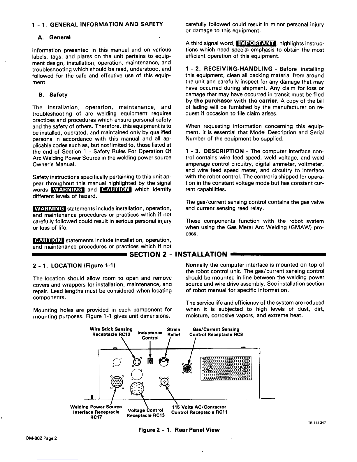
Normally
the
computer
interfaceismountedontop
of
the
robot control
unit.
The
gas/current
sensing
control
shouldbemountedinline
between
the
welding
power
source
and
wire
drive
assembly.
See
installation section
of
robot
manual
for
specific information.
The
service
life
and
efficiencyofthe
system
are
reduced
whenitis
subjectedtohigh
levelsofdust,
dirt,
moisture,
corrosive
vapors,
and
extreme
heat.
re-114
347
Wire
Stick
Sensing
Strain
Gas/current
Sensing
Receptacle
RC12
Inductance
Relief
control
Receptacle
RC9
control
Welding Power
Source
115
Volts
Ac/contactor
Interface
Receptacle
Voltage
control
control
ReceptacleRd1
RC17
Receptacle
RC13
Figure
2-1.
Rear
Panel
View
OM-882
Page
2
2-2.
GAS/CURRENT
SENSING
CONTROL
CON
-
NECTIONS
(Figures
2-1
And
2-2)
N-.
ELECTRIC
SHOCK
can kill.
•
Do
not
touch
live electrical
parts.
•
Shut
down
unit,
welding
power
source,
and
robot, and
disconnect
input
power
employing
“lockout/tagging
procedures”
before
makingin-
terconnections.
Lockout/tagging
procedures
consistofpadlocking
line
disconnect
switchinopen
position,
removing
fuses
from fuse
box,
or shutting
off
and
red-tagging
circuit
breakerorother disconnecting
device.
A.
Computer
Interface-Gas/Current
Sensing
Control
Connections
1.
Align
keyways,
insert 14-pin
Amp
plug into
mat
-
ching
receptacleoncomputer
interface,
and
rotate threaded
collar
fully
clockwise.
2.
Align
keyways,
insert
16-pin
Amp
plug
into
mat-
ching
receptacleongas/current
sensing
control,
and
rotate threaded
collar
fully
clockwise.
B.
Gas/Current
Sensing
Control-Motor
Con
-
nections
Align
keyways,
insert
14-pin
plug
from
motor
into
mat-
ching
receptacleongas/current
sensing
control,
and
rotate threaded
collar
fully
clockwise.
C.
Weld
Cable
Connections
Route
cable
from
welding
power
source
positive
weld
output
terminal,
through
the
gas/current
sensing
con
-
trol, to
the
wire
drive
assembly
and
connect
cable
to
weld
cable
terminal
(see
Motor/Drive
Assembly
Owner’s
Manual
for
location).
D.
Gas
Connections
Connect
hose
from
gas
regulator/flowmeter
(customer
supplied)atgas
source
to IN finingongas/current
sen
-
sing
control.
Connect
gas
hose from
wire
drive
assemblytofittingongas/current
sensing
control.
The
gas
flow
must
be
accurately
controlled by
a
regulator/flowmeter
at
the
source.
E.
Touch
Sensor Connections
Connect
cord with
two
friction
connectors
coming
from
gas/current
sensing
controltotouch
sensor
leads
com
-
ing
from
outlet cable. Polarityisnot
important
for
this
connection.
2-3.
COMPUTER
INTERFACE-WELDING
POWER
SOURCE
CONNECTIONS
(Figures
2-1
And
2-2)
ELECTRIC
SHOCK
can kill.
•
Do
not
touch
live electrical
parts.
•
Shut
down
unit,
welding
power
source,
and
robot, and
disconnect
input
power
employing
“lockout/tagging
procedures”
before
makingin-
terconnections.
Lockout/tagging
procedures consistofpadlocking
line
disconnect
switchinopen
position,
removing
fuses
from
fuse box,orshutting
off
and
red-tagging
circuit
breakerorother disconnecting
device.
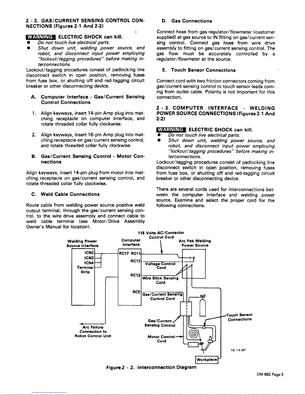
There
are several
cords
used
for
interconnections
bet
-
ween
the computer
interface
and
welding
power
source.
Examine
and
select
the
proper
cord
for
the
following
connections.
115
Volts
AC/Contactor
control
Cord
Computer
Interface
RC17
Rd
Arc
Failure
Connection
In
Robot
Control
UnIt
Arc
Pak
Welding
Power
Source
Sensor
GaslCurrent
Sensing
Control
Motor
Control-
Cord
TB-i14357
Figure
2-2.
Interconnection
Diagram
OM-882
Page
3
 Loading...