

Miller Electric Tandem Systems Owner's Manual
Millerfi
OWNERS
MANUAL
Read
and
follow
these
instructions
and
all
safety
blocks
carefully.
Have
only
trained
and
qualified
persons
install,
operate,
or
service
this
unit.
Call
your
distributor
if
you
do
not
understand
the
directions.
''~~
__~'
~'~1~3
April
1993
Effective
With
Style
No.
JD-25
Form:
OM-1553
Tandem
Systems
U
U
U
For
help,
call
your
distributor
or:
MILLER
ELECTRIC
Mfg.
Co.,
P.O.
Box
1079,
Appleton,
WI
54912
414-734-9821
cover
8/92
-
ST
I
10
784-A
PRINTED
IN
USA
u-I.
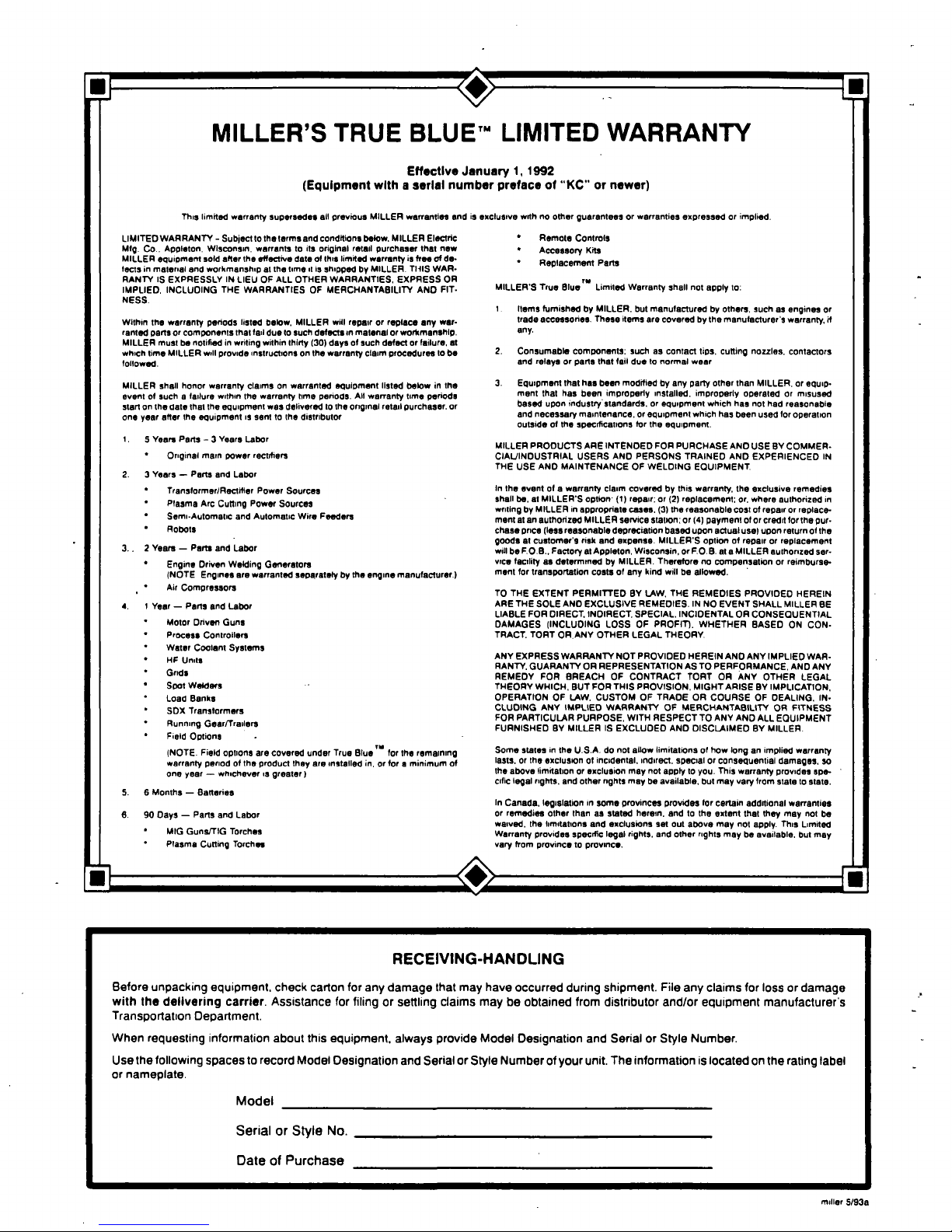
MILLERS
TRUE
BLUETM
LIMITED
WARRANTY
Effective
January
1,
1992
(Equipment
with
a
serial
number
preface
of
ICC
or
newer)
This
limited
warranty
supersedes
all
previous
MILLER
warranties
and
is
exclusive
with
no
other
guarantees
or
warranties
expressed
or
implied.
ii
LIMITED
WARRANTY
-
Subject
to
the
terms
and
conditions
below.
MILLER
Electric
Mtg.
Co..
Appleton.
WIsconsin,
warrants
to
its
original
retail
purchaser
that
new
MILLER
equipment
sold
after
the
effective
date
of
this
limited
warranty
is
freeofde
lads
in
material
and
workmanship
at
the
time
it
is
shipped
by
MILLER.
TIltS
WAR
RANTY
IS
EXPRESSLY
IN
LIEU
OF
ALL
OTHER
WARRANTIES,
EXPRESS
OR
IMPLIED,
INCLUDING
TNE
WARRANTIES
OF
MERCHANTABILITY
AND
FIT
NESS.
Within
the
warranty
periods
listed
below.
MILLER
will
repair
or
replace
any
war
ranted
partsorcomponents
that
tail
due
to
such
defects
in
matenal
or
workmanship.
MILLER
must
be
notified
in
writing
within
thIrty
130)
days
ot
such
defect
or
tsilure,
at
which
time
MILLER
will
provide
instructions
on
the
warranty
claim
procedures
to
be
followed.
MILLER
shall
honor
warranty
claimsonwarranted
eguloment
lIsted
below
in
the
event
ot
such
a
lailure
within
the
warranty
time
periods.
All
warranty
time
periods
start
on
the
date
that
the
equipment
was
delivered
to
the
original
retail
purchaser.
or
one
year
after
the
equipment
is
sent
to
the
distributor
t.
5
Years
Parts3Years
Labor
*
Original
main
power
rectifiers
2.3Years
Parts
and
Labor
*
Transtormer/Ractifler
Power
Sources
Plasma
Arc
Cutting
Power
Sources
Semi-Automatic
and
Automatic
Wire
Feeders
Robots
3.,
2
Years
Parts
and
Labor
Engine
Driven
Welding
Generators
(NOTE
Engines
are
warranted
separately
by
the
engine
manufacturer.)
Air
Compressors
4.
t
Year
Parts
and
Labor
Motor
Driven
Guns
Process
Controllers
Water
Coolant
Systems
HF
Units
Grids
Soot
Welders
Load
Banks
SDX
Transtormers
Running
Gear/Trailers
Field
Options
(NOTE.
Field
options
are
covered
under
True
Bluer
for
the
remaining
warranty
period
of
the
product
they
are
installed
in,
or
foraminimum
of
one
year
whichever
is
greater
I
6
Months
Batteries
90
Days
Pans
and
Labor
MIG
Guns/TIG
Torches
Plasma
Cutting
Torches
Remote
Controls
Accessory
Kits
Replacement
Pans
MILLERS
True
Bluer
Limited
Warranty
shall
not
apply
to:
1.
Items
tumished
by
MILLER,
but
manutactured
by
others,
such
as
engines
or
trade
accessories.
These
items
are
covered
by
the
manufacturers
warranty,
if
any.
2.
Consumable
components;
such
as
contact
tips,
cutting
nozzles,
contactors
and
relays
or
pans
that
tail
duetonormal
wear
3.
Equipment
that
has
been
modified
by
any
party
other
than
MILLER.
or
equip
ment
that
has
been
improperly
installed,
improperly
operaled
or
misused
based
upon
industry
standards.
or
equipment
which
has
not
had
reasonable
and
necessary
maintenance,
or
equipment
which
has
been
used
tor
operation
outsideofthe
specifications
for
the
equipment.
MILLER
PRODUCTS
ARE
INTENDED
FOR
PURCHASE
AND
USEBYCOMMER
CIAL/INDUSTRIAL
USERS
AND
PERSONS
TRAINED
AND
EXPERIEHCED
IN
THE
USE
AND
MAINTENANCE
OF
WELDING
EQUIPMENT
In
the
event
ot
a
warranty
claim
covered
by
this
warranty,
the
exclusive
remedies
shall
be,
at
MILLERS
option
(1)
repair;
or
(2)
replacement;
or.
where
authorized
in
writing
by
MILLER
in
appropriate
cases,
(3)
the
reasonable
cost
of
repair
or
replace
ment
at
an
authorized
MILLER
service
station;
or
(4)
payment
of
or
credit
for
the
pur
chase
price
(less
reasonable
depreciation
based
upon
actual
usel
upon
return
of
the
goods
at
customers
risk
and
expense.
MILLERS
option
of
repair
or
replacement
will
be
FOB.,
Factory
at
Appleton,
Wisconsin.
or
F.O.
B.
at
a
MILLER
authorized
ser
vice
tacility
as
determined
by
MILLER.
Therefore
no
compensation
or
reimburse
ment
for
transportation
costs
ot
any
kind
will
be
allowed.
TO
THE
EXTENT
PERMItTED
BY
LAW.
THE
REMEDIES
PROVIDED
HEREIN
ARE THE
SOLE
AND
EXCLUSIVE
REMEDIES.INNO
EVENT
SHALL
MILLER
BE
LIABLE
FOR
DIRECT,
INDIRECt
SPECIAL,
INCIDENTAL
OR
CONSEQUENTIAL
DAMAGES
(INCLUDING
LOSS
OF
PROFIT).
WHETHER
BASED
ON
CON
TRACt
TORT
OR.ANY
OTHER
LEGAL
THEORY.
ANY
EXPRESS
WARRANTY
NOT
PROVIDED
HEREIN
AND
ANY
IMPLIED
WAR
RANTY.
GUARANTY
OR
REPRESENTATION
AS
TO
PERFORMANCE.
AND
ANY
REMEDY
FOR
BREACH
OF
CONTRACT
TORT
OR
ANY
OTHER
LEGAL
THEORY
WHICH.
BUT
FOR
THIS
PROVISION,
MIGHT
ARISE
BY
IMPLICATION,
OPERATION
OF
LAW.
CUSTOM
OF
TRADE
OR
COURSE
OF
DEALING,
IN
CLUDING
ANY
IMPLIED
WARRANTY
OF
MERCHANTABILITY
OR
FITNESS
FOR
PARTICULAR
PURPOSE,
WITH
RESPECT
TO
ANY
AND
ALL
EQUIPMENT
FURNISHED
BY
MILLERISEXCLUDED
AND
DISCLAIMED
BY
MILLER.
Some
states
in
the
U.S.A.
do
not
allow
limitationsothow
long
an
implied
warranty
lasts,orthe
exclusionotincidental,
indirect,
specialorconsequential
damages.
so
the
above
limitationorexclusion
may
not
apply
to
you.
This
warranty
provides
spa
cilic
legal
rights,
and
other
rights
may
be
available,
but
may
vary
from
slate
to
state.
In
Canada,
legislation
in
some
provinces
provides
(or
certain
additional
warranties
or
remedies
other
than
as
stated
herein,
and
to
the
extent
that
they
may
not
be
waived,
the
limitations
and
esclusions
set
out
above
may
not
apply.
This
Limited
Warranty
provides
specific
legal
rights,
and
other
rights
may
be
available,
but
may
vary
from
province
to
province.
5.
6.
al-
RECEIVING-HANDLING
Before
Unpacking
equipment,
Check
carton
for
any
damage
that
may
have
occurred
during
shipment.
File
any
Claims
for
loss
or
damage
with
the
delivering
carrier.
Assistance
for
filing
or
settling
claims
may
be
obtained
from
distributor
and/or
equipment
manufacturers
Transportatton
Department.
When
requesting
information
about
this
equipment,
always
provide
Model
Designation
and
Serial
or
Style
Number
Use
the
following
spaces
to
record
Model
Designation
and
Serial
or
Style
Number
of
your
unit,
The
information
is
located
on
the
rating
label
or
nameplate.
Model
_________
Serial
or
Style
No,
Date
of
Purchase
miller
5/93a
TABLE
OF
CONTENTS
Section
No.
Page
No.
SECTION
1
-
SAFETY
RULES
FOR
OPERATION
OF
ARC
WELDING
POWER
SOURCE
1-1.
Introduction
1
1
-
2.
General
Precautions
1
1
-
3.
Arc
Welding
4
1
-
4.
Standards
Booklet
Index
6
SECTION
2
-
INTRODUCTION
2
-
1.
General
Information
And
Safety
7
2-2.
Receiving-Handling
7
2
-
3.
Description
7
SECTION
3
-
INSTALLATION
3-1.
Location
8
3-2.
Drive
Roll
And
Wire
Guide
Installation
8
3-3.
Welding
Gun
Connections
9
3
-4.
Drive
Motor
Connections
9
3
-
5.
Trailing
Gun
Position
Adjustment
9
3
-
6.
Flux
Hopper
Connections
10
3
-
7.
Flux
Nozzle
Adjustment
10
3-8.
Gun
Component
Changes
When
Changing
Wire
Size
10
3
-
9.
Weld
Cable
Connections
11
SECTION
4
-
SEQUENCE
OF
OPERATION
4-1.
Welding
Wire
Threading
11
4
-
2.
Submerged
Arc
Welding
(SAW)
12
4
-
3.
Shutting
Down
12
SECTION
5
-
MAINTENANCE
5-1.
Inspection
And
Upkeep
13
5
-
2.
Cleaning
Of
Drive
Rolls:
.
-
13
5
-
3.
Brush
Inspection
&
Replacement
13
SECTION
6
-
TROUBLESHOOTING
6-1.
General
14
6
-
2.
Troubleshooting
Chart
14

SECTION
1
-
SAFETY
RULES
FOR
OPERATION
OF
ARC
WELDING
POWER
SOURCE
1-1.
INTRODUCTION
-
We
learn
by
experience.
Learning
safety
through
personal
experience,
like
a
child
touching
a
hot
stove
is
harmful,
wasteful,
and
un
wise.
Let
the
experience
of
others
teach
you.
Safe
practices
developed
from
experience
in
the
use
of
welding
and
cutting
are
described
in
this
manual.
Research,
development,
and
field
experience
have
evolved
reliable
equipment
and
safe
installation,
opera
tion,
and
servicing
practices.
Accidents
occur
when
equipment
is
improperly
used
or
maintained.
The
reason
for
the
safe
practices
may
not
always
be
given.
Some
are
based
on
common
sense,
others
may
require
technical
volumes
to
explain.
It
is
wiser
to
follow
the
rules.
Read
and
understand
these
safe
practices
before
at
tempting
to
install,
operate,
or
service
the
equipment.
Comply
with
these
procedures
as
applicable
to
the
par
ticular
equipment
used
and
their
instruction
manuals,
for
personal
safety
and
for
the
safety
of
others.
Failure
to
observe
these
safe
practices
may
cause
serious
injury
or
death.
When
safety
becomes
a
habit,
the
equipment
can
be used
with
confidence.
These
safe
practices
are
divided
into
two
Sections:
1
-
General
Precautions,
common
to
arc
welding
and
cutting;
and
2
-
Arc
Welding
(and
Cutting)
(only).
Reference
standards:
Published
Standards
on
safety
are
also
available
for
additional
and
more
complete
pro
cedures
than
those
given
in
this
manual.
They
are
listed
in
the
Standards
Index
in
this
manual.
ANSI
Z49.1
is
the
most
complete.
The
National
ElectricalCode,
Occupational
Safety
and
Health
Administration,
local
industrial
codes,
and
local
inspection
requirements
also
provide
a
basis
for
equip
ment
installation,
use,
and
service.
1-2.
GENERAL
PRECAUTIONS
Different
arc
welding
processes,
electrod.
alloys,
and
fluxes
can
produce
different
fumes,
gases,
and
radiation
levels.
In
addItion
to
the
information
in
this
manual,
be
sure
to
consult
flux
and
alec
trode
manufacturers
for
specific
technical
data
and
precautionary
measures
concerning
their
material.
A.
Burn
Prevention
Wear
protective
clothing
-
gauntlet
gloves
designed
for
use
in
welding,
hat,
and
high
safety-toe
shoes.
Button
shirt
collar
and
pocket
flaps,
and
wear
cuftless
trousers
to
avoid
entry
of
sparks
and
slag.
Wear
helmet
with
safety
goggles
or
glasses
with
side
shields
underneath,
appropriate
filter
lenses
or
plates
(protected
by
clear
cover
glass).
This
is
a
MUST
for
welding
or
cutting,
(and
chipping)
to
protect
the
eyes
from
radiant
energy
and
flying
metal.
Replace
cover
glass
when
broken,
pitted,
or
spattered.
See
1
-3A.2.
Avoid
oily
or
greasy
clothing.
A
spark
may
ignite
them.
Hot
metal
such
as
electrode
stubs
and
workpieces
should
never
be
handled
without
gloves.
Medical
first
aid
and
eye
treatment.
First
aid
facilities
and
a
qualified
first
aid
person
should
be
available
for
each
shift
unless
medical
facilities
are
close
by
for
im
mediate
treatment
of
flash
burns
of
the
eyes
and
skin
burns.
Ear
plugs
should
be
worn
when
working
on
overhead
or
in
a
confined
space.
A
hard
hat
should
be
worn
when
others
work
overhead.
Flammable
hair
preparations
should
not
be
used
by
per
sons
intending
to
weld
or
cut.
B.
Toxic
Fume
Prevention
Severe
discomfort,
illness
or
death
can
result
from
fumes,
vapors,
heat,
or
oxygen
enrichment
or
depletion
that
welding
(or
cutting)
may
produce.
Prevent
them
with
adequate
ventilation
as
described
in
ANSI Stan
dard.Z49.1
listed
1
in
Standards
index.
NEVER
ventilate
with
oxygen.
Lead
-,
cadmium
-,
zinc
-,
mercury
-,
and
beryllium
-
bearing
and
similar
materials,
when
welded
(or
cut)
may
produce
harmful
concentrations
of
toxic
fumes.
Ade
quate
local
exhaust
ventilation
must
be
used,
or
each
person
in
the
area as
well
as
the
operator
must
wear
an
air-supplied
respirator.
For
beryllium,
both
must
be
us
ed.
Metals
coated
with
or
containing
materials
that
emit
toxic
fumes
should
not
be
heated
unless
coating
is
removed
from
the
work
surface,
the
area
is
well
ven
tilated,
or
the
operator
wears
an
air-supplied
respirator.
Work
in
a
confined
space
only
whileitis
being
ven
tilated
and,
if
necessary,
while
wearinganair-supplied
respirator.
Gas
leaks
in
a
confined
space
should
be
avoided.
Leaked
gas
in
large
quantities
can
change
oxygen
con
centration
dangerously.
Do
not
bring
gas
cylinders
into
a
confined
space.
Leaving
confined
space,
shut
OFF
gas
supply
at
source
to
prevent
possible
accumulation
of
gases
in
the
space
if
downstream
valves
have
been
accidently
opened
or
left
open.
Check
to
be
sure
that
the
space
is
safe
before
re-entering
it.
Vapors
from
chlorinated
solvents
can
be
decomposed
by
the
heat
of
the
arc
(or
flame)
to
form
PHOSGENE,
a
OM-1553
Page
1
highly
toxic
gas,
and
other
lung
and
eye
irritating
pro
ducts.
The
ultraviolet
(radiant)
energy
of
the
arc
can
also
decompose
trichioroethylene
and
per
chloroethylene
vapors
to
form
phosgene.
DO
NOT
WELD
or
cut
where
solvent
vapors
can
be
drawn
into
the
welding
or
cutting
atmosphere
or
where
the
radiant
energy
can
penetrate
to
atmospheres
containing
even
minute
amounts
of
trichioroethylene
or
per
chioroethylene.
C.
Fire
and
Explosion
Prevention
Causes
of
fire
and
explosion
are:
combustibles
reached
by
the
arc,
flame,
flying
sparks,
hot
slag
or
heated
material;
misuse
of
compressed
gases
and
cylinders;
and
short
circuits.
BE
AWARE
THAT
flying
sparksorfalling
slag
can
pass
through
cracks,
along
pipes,
through
windows
or
doors,
and
through
wall
or
floor
openings,
Out
of
sight
of
the
goggled
operator.
Sparks
and
slag
can
fly
35
feet.
To
prevent
fires
and
explosion:
Keep
equipment
clean
and
operable,
free
of
oil,
grease,
and
(in
electrical
parts)
of
metallic
particles
that
can
cause
short
circuits.
If
combustibles
are
in
area,
do
NOT
weld
or
cut.
Move
the
work
if
practicable,
to
an
area
freeofcombustibles.
Avoid
paint
spray
rooms,
dip
tanks,
storage
areas,
yen
.tilators.
If
the
work
cannot
be
moved,
move
com
bustibles
at
least
35
feet
away
Out
of
reach
of
sparks
and
heat;
or
protect
against
ignition
with
suitable
and
snug-fitting,
fire-resistant
covers
or
shields.
Walls
touching
combustibles
on
opposite
sides
should
not
be
welded
on
(or
cut).
Walls,
ceilings1
and
floor
near
work
should
be
protected
by
heat-resistant
covers
or
shields.
Fire
watcher
must
be
standing
by
with
suitable
fire
ex
tinguishing
equipment
during
and
for
some
time
after
welding
or
cutting
if:
a.
appreciable
combustibles
(including
building
construction)
are
within
35
feet
b.
appreciable
combustibles
are
further
than
35
feet
but
can
be
ignited
by
sparks
c.
openings
(concealed
or
visible)
in
floors
or
walls
within
35
feet
may
expose
com
bustibles
to
sparks
d.
combustibles
adjacent
to
walls,
ceilings,
roofs,
or
metal
partitions
can
be
ignited
by
radiant
or
conducted
heat.
Hot
work
permit
should
be
obtained
before
operation
to
ensure
supervisors
approval
that
adequate
precautions
have
been
taken.
After
work
is
done,
check
that
area
is
free
of
sparks,
glowing
embers,
and
flames.
An
empty
container
that
held
combustibles,
or
that
can
produce
flammable
or
toxic
vapors
when
heated,
must
never
be
welded
on
or
cut,
unless
container
has
first
been
cleaned
as
described
in
AWS
Standard
A6.O,
listed
3
in
Standards
index.
This
includes:
a
thorough
steam
or
caustic
cleaning
(or
a
solvent
or
water
washing,
depending
on
the
com
bustibles
solubility)
followed
by
purging
and
inerting
with
nitrogen
or
carbon
dioxide,
and
using
protective
equipment
as
recommended
in
A6.O.
Waterfilling
just
below
working
level
may
substitute
for
inerting.
A
container
with
unknown
contents
should
be
cleaned
(see
paragraph
above).
Do
NOT
depend
on
sense
of
smell
or
sight
to
determine
if
it
is
safe
to
weld
or
cut.
Hollow
castings
or
containers
must
be
vented
before
welding
or
cutting.
They
can
explode.
Explosive
atmospheres.
Never
weld
or
cut
where
the
air
may
contain
flammable
dust,
gas,
or
liquid
vapors
(such
as
gasoline).
D.
Compressed
Gas
Equipment
Standard
precautions.
Comply
with
precautions
in
this
manual,
and
those
detailed
in
CGA
Standard
P-i,
PRECAUTIONS
FOR
SAFE
HANDLING
OF
COMPRESSED
GASES
IN
CYLINDERS,
listed6in
Standards
index.
1.
Pressure
Regulators
Regulator
relief
valve
is
designed
to
protect
only
the
regulator
from
overpressure;
it
is
not
intended
to
protect
any
downstream
equipment.
Provide
such
protection
with
one
or
more
relief
devices.
Never
connect
a
regulator
to
a
cylinder
containing
gas
other
than
that
for
which
the
regulator
was
designed.
Remove
faulty
regulator
from
service
immediately
for
repair
(first
close
cylinder
valve).
The
following
symptoms
indicate
a
faulty
regulator:
Leaks
-
if
gas
leaks
externally.
Excessive
Creep
-
if
delivery
pressure
continues
to
rise
with
downstream
valve
closed.
Faulty
Gauge
-
if
gauge
pointer
does
not
move
off
stop
pin
when
pressurized,
nor
returns
to
stop
pin
after
pressure
release.
Repair.
Do
NOT
attempt
repair.
Send
faulty
regulators
for
repair
to
manufacturers
designated
repair
center,
where
special
techniques
and
tools
are
used
by
trained
personnel.
2.
Cylinders
Cylinders
must
be
handled
carefully
to
prevent
leaks
and
damage
to
their
walls,
valves,
or
safety
devices:
Avoid
electrical
circuit
contact
with
cylinders
in
cluding
third
rails,
electrical
wires,
or
welding
cir
cuits.
They
can
produce
short
Circuit
arcs
that
may
lead
to
a
serious
accident.
(See
i-3C.)
OM-1553
Page
2
ICC
or
DOT
marking
must
be
on
each
cylinder.
It
is
an
assurance
of
safety
when
the
cylinder
is
properly
handled.
Identifying
gas
content.
Use
only
cylinders
with
name
of
gas
marked
on
them;
do
not
rely
on
color
to
identify
gas
content.
Notify
supplier
if
unmarked.
NEVER
DEFACE
or
alter
name,
number,
or
other
markings
on
a
cylinder.
It
is
illegal
and
hazardous.
Empties:
Keep
valves
closed,
replace
caps
securely;
mark
MT;
keep
them
separate
from
FULLS
and
return
promptly.
Prohibited
use.
Never
use
a
cylinder
or
its
contents
for
other
than
its
intended
use,
NEVER
as
a
support
or
roller.
Locate
or
secure
cylinders
so
they
cannot
be
knocked
over.
Passageways
and
work
areas.
Keep
cylinders
clear
of
areas
where
they
may
be
struck.
Transporting
cylinders.
With
a
crane,
use
a
secure
sup
port
such
as
a
platform
or
cradle.
Do
NOT
lift
cylinders
off
the
ground
by
their
valves
or
caps,
or
by
chains,
slings,
or
magnets.
Do
NOT
expose
cylinders
to
excessive
heat,
sparks,
slag,
and
flame,
etc.
that
may
cause
rupture.
Do
not
allow
contents
to
exceed
130F.
Cool
with
water
spray
where
such
exposure
exists.
-
Protect
cylinders
particularly
valves
from
bumps,
falls,
falling
objects,
and
weather.
Replace
caps
securely
when
moving
cylinders.
Stuck
valve.
Do
NOT
use
a
hammer
or
wrench
to
open
a
cylinder
valve
that
can
not
be
opened
by
hand.
Notify
your
supplier.
Mixing
gases.
Never
try
to
mix
any
gases
in
a
cylinder.
Never
refill
any
cylinder.
Cylinder
fittings
should
never
be
modified
or
exchang
ed.
Coil
excess
hose
to
prevent
kinks
and
tangles.
Protect
hose
from
damage
by
sharp
edges,
and
by
sparks,
slag,
and
open
flame.
Examine
hose
regularly
for
leaks,
wear,
and
loose
con
nections.
Immerse
pressured
hose
in
water;
bubbles
in
dicate
leaks.
Repair
leaky
or
worn
hose
by
cutting
area
Out
and
splic
ing
(1-2D3).
Do
NOT
use
tape.
4.
Proper
Connections
Clean
cylinder
valve
outlet
of
impurities
that
may
clog
orifices
and
damage
seats
before
connecting
regulator.
Except
for
hydrogen,
crack
valve
momentarily,
pointing
outlet
away
from
people
and
sources
of
ignition.
Wipe
with
a
clean
lintless
cloth.
Match
regulator
to
cylinder.
Before
connecting,
check
that
the
regulator
label
and
cylinder
marking
agree,
and
that
the
regulator
inlet
and
cylinder
outlet
match.
NEVER
CONNECT
a
regulator
designed
for
a
particular
gas
or
gases
to
a
cylinder
containing
any
other
gas.
Tighten
connections.
When
assembling
threaded
con
nections,
clean
and
smooth
seats
where
necessary.
Tighten.
If
connection
leaks,
disassemble,
clean,
and
retighten
using
properly
fitting
wrench.
Adapters.
Use
a
CGA
adapter
(available
from
your
sup
plier)
between
cylinder
and
regulator,
if
one
is
required.
Use
two
wrenches
to
tighten
adapter
marked
RIGHT
and
LEFT
HAND
threads.
Regulator
outlet
(or
hose)
connections
may
be
iden
tified
by
right
hand
threads
for
oxygen
and
left
hand
threads
(with
grooved
hex
on
nut
or
shank)
for
fuel
gas.
5.
Pressurizing
Steps:
Drain
regulator
of
residual
gas
through
suitable
vent
before
opening
cylinder
(or
manifold
valve)
by
turning
adjusting
screw
in
(clockwise).
Draining
prevents
ex
cessive
compression
heat
at
high
pressure
seat
by
allowing
seat
to
open
on
pressurization.
Leave
adjusting
screw
engaged
slightlyonsingle-stage
regulators.
3.
Hose
Stand
to
side
of
regulator
while
opening
cylinder
valve.
Prohibited
use.
Never
use
hose
other
than
that
designed
for
the
specified
gas.
A
general
hose
identification
rule
is:
red
for
fuel
gas,
green
for
oxygen,
and
black
for
inert
gases.
Use
ferrules
or
clamps
designed
for
the
hose
(not
or
dinary
wireorother
substitute)
as
a
binding
to
connect
hoses
to
fittings.
No
copper
tubing
splices.
Use
only
standard
brass
fit
tings
to
splice
hose.
Avoid
long
runs
to
prevent
kinks
and
abuse.
Suspend
hose
off
ground
to
keep
it
from
being
run
over,
stepped
on,
or
otherwise
damaged.
Open
cylinder
valve
slowly
so
that
regulator
pressure
in
creases
slowly.
When
gauge
is
pressurized
(gauge
reaches
regulator
maximum)
leave
cylinder
valve
in
following
position:
For
oxygen,
and
inert
gases,
open
fully
to
seal
stem
against
possible
leak.
For
fuel
gas,
opento
less
than
one
turn
to
permit
quick
emergency
shutoff.
Use
pressure
charts
(available
from
your
supplier)
for
safe
and
efficient,
recommended
pressure
settings
on
regulators.
Check
for
leaks
on
first
pressurization
and
regularly
there-after.
Brush
with
soap
solution
(capful
of
Ivory
OM-1553
Page
3
Liquid
or
equivalent
per
gallon
of
water).
Bubbles
in
dicate
leak.
Clean
off
soapy
water
after
test;
dried
soap
is
combustible.
E.
User
Responsibilities
Remove
leaky
or
defective
equipment
from
service
im
mediately
for
repair.
See
User
Responsibility
statement
in
equipment
manual.
F.
Leaving
Equipment
Unattended
Close
gas
supply
at
source
and
drain
gas.
G.
Rope
Staging-Support
Rope
staging-support
should
not
be
used
for
welding
or
cutting
operation;
rope
may
burn.
1-3.
ARC
WELDING
-
Comply
with
precautions
in
1-1,
1-2.
and
this
section.
Arc
Welding,
properly
done,
is
a
safe
process,
butacareless
operator
invites
trouble.
The
equipment
carries
high
currents
at
significant
voltages.
The
arc
is
very
bright
and
hot.
Sparks
fly,
fumes
rise,
ultraviolet
and
infrared
energy
radiates,
weidments
are
hot,
and
compressed
gases
may
be
us
ed.
The
wise
operator
avoids
unnecessary
risks
and
pro
tects
himself
and
others
from
accidents.
Precautions
are
described
here
and
in
standards
referencedinindex.
A.
Burn
Protection
Comply
with
precautions
in
1-2.
The
welding
arc
is
intense
and
visibly
bright.
Its
radia
tion
can
damage
eyes,
penetrate
lightweight
clothing,
reflect
from
light-colored
surfaces,
and
burn
the
skin
and
eyes.
Skin
burns
resemble
acute
sunburn,
those
from
gas-shielded
arcs
are
more
severe
and
painful.
DONT
GET
BURNED;
COMPLY
WITH
PRECAU
TIONS.
1.
Protective
Clothing
Wear
long-sleeve
clothing
(particularly
for
gas-shielded
arc)
in
addition
to
gloves,
hat,
and
shoes
(1-2A).
As
necessary,
use
additional
protective
clothing
such
as
leather
jacket
or
sleeves,
flame-proof
apron,
and
fire-
resistant
leggings.
Avoid
outergarments
of
untreated
cotton.
Bare
skin
protection.
Wear
dark,
substantial
clothing.
Button
collar
to
protect
chest
and
neck
and
button
pockets
to
prevent
entry
of
sparks.
2.
Eye
and
Head
Protection
Protect
eyes
from
exposure
to
arc.
NEVER
look
at
an
electric
arc
without
protection.
Welding
helmet
or
shield
containing
a
filter
plate
shade
no.
12
or
denser
must
be
used
when
welding.
Place
over
face
before
striking
arc.
Trademark
of
Proctor
&
Gamble.
Protect
filter
plate
with
a
clear
cover
plate.
Cracked
or
broken
helmet
or
shield
should
NOT
be
worn;
radiation
can
pass
through
to
cause
burns.
Cracked,
broken,
or
loose
filter
plates
must
be
replaced
IMMEDIATELY.
Replace
clear
cover
plate
when
broken,
pitted,
or
spattered.
Flash
goggles
with
side
shields
MUST
be
worn
under
the
helmet
to
give
some
protection
to
the
eyes
should
the
helmet
not
be
lowered
over
the
face
before
an
arc
is
struck.
Looking
at
an
arc
momentarily
with
unprotected
eyes
(particularlyahigh
intensity
gas-shielded
arc)
can
cause
a
retinal
burn
that
may
leave
a
permanent
dark
area
in
the
field
of
vision.
3.
Protection
of
Nearby
Personnel
Enclosed
welding
area.
For
production
welding,
a
separate
room
or
enclosed
bay
is
best.
In
open
areas,
surround
the
operation
with
low-reflective,
non-
combustible
screens
or
panels.
Allow
for
free
air
circula
tion,
particularly
at
floor
level.
Viewing
the
weld.
Provide
face
shields
for
all
persons
who
will
be
looking
directly
at
the
weld.
Others
working
in
area.
See
that
all
persons
are
wearing
flash
goggles.
Before
starting
to
weld,
make
sure
that
screen
flaps
or
bay
doors
are
closed.
B.
Toxic
Fume
Prevention
Comply
with
precautions
in
1-2B.
Generator
engine
exhaust
must
be
ventedtothe
outside
air.
Carbon
monoxide
can
kill.
C.
Fire
and
Explosion
Prevention
Comply
with
precautions
in
1
-2C.
Equipments
rated
capacity.
Do
not
overload
arc
welding
equipment.
It
may
overheat
cables
and
cause
a
fire.
Loose
cable
connections
may
overheat
or
flash
and
cause
a
fire.
Never
strike
an
arc
on
a
cylinder
or
other
pressure
vessel.
It
creates
a
brittle
area
that
can
cause
a
violent
rupture
or
lead
to
such
a
rupture
later
under
rough
handling.
D.
Compressed
Gas
Equipment
Comply
with
precautions
in
1
-2D.
OM1553
Page
4

E.
Shock
Prevention
2.
Electrode
Holders
Exposed
hot
conductors
or
other
bare
metal
in
the
welding
circuit,
or
in
ungrounded,
electrically-HOT
equipment
can
fatally
shock
a
person
whose
body
becomes
a
conductor.
DO
NOT
STAND,
SIT,
LIE.
LEAN
ON,
OR
TOUCH
a
wet
surface
when
welding,
without
suitable
protection.
To
protect
against
shock:
Keep
body
and
clothing
dry.
Never
work
in
damp
area
without
adequate
insulation
against
electrical
shock.
Stay
on
a
dry
duckboard,
or
rubber
mat
when
damp
ness
or
sweat
can
not
be
avoided.
Sweat,
sea
water,
or
moisture
between
body
and
an
electrically
HOT
part
-
or
grounded
metal
-
reduces
the
body
surface
electrical
resistance,
enabling
dangerous
and
possibly
lethal
currents
to
flow
through
the
body.
1.
Grounding
the
Equipment
When
arc
welding
equipment
is
grounded
according
to
the
National
Electrical
Code,
and
the
work
is
grounded
according
to
ANSI
Z49.1
SafetyInWelding
And
Cut
ting,
a
voltage
may
exist
between
the
electrode
and
any
conducting
object.
Examples
of
conducting
objects
include,
but
are
not
limited
to,
buildings,
electrical
tools,
work
benches,
welding
power
source
cases,
workpieces,
etc.
Never
touch
the
electrode
and
any
metal
object
unless
the
welding
power
source
is
off.
When
installing,
connect
the
frames
of
each
unit
such
as
welding
power
source,
control,
work
table,
and
water
circulator
to
the
building
ground.
Conductors
must
be
adequate
to
carry
ground
currents
safely.
Equipment
made
electrically
HOT
by
stray
current
may
shock,
possibly
fatally.
Do
NOT
GROUND
to
electrical
conduit,
or
to
a
pipe
carrying
ANY
gas
or
a
flammable
li
quid
such
as
oilorfuel.
Three-phase
connection.
Check
phase
requirements
of
equipment
before
installing,ifonly
3-phase
power
is
available,
connect
single-phase
equipment
to
only
two
wires
of
the
3-phase
line.
Do
NOT
connect
the
equip
ment
ground
lead
to
the
third
(live)
wire,
or
the
equip
ment
will
become
electrically
HOT
-
a
dangerous
condi
tion
that
can
shock,
possibly
fatally.
Before
welding,
check
ground
for
continuity.
Be
sure
conductors
are
touching
bare
metal
of
equipment
frames
at
connections.
Ifaline
cord
with
a
ground
lead
is
provided
with
the
equipment
for
connection
to
a
switchbox,
connect
the
ground
lead
to
the
grounded
switchbox.
If
a
three-
prong
plug
is
added
for
connection
to
a
grounded
mating
receptacle,
the
ground
lead
must
be
connected
to
the
ground
prong
only.
If
the
line
cord
comes
with
a
three-prong
plug,
connect
to
a
grounded
mating
recep
tacle.
Never
remove
the
ground
prong
from
a
plug,
or
use
a
plug
withabroken
oft
ground
prong.
Fully
insulated
electrode
holders
should
be
used.
Do
NOT
use
holders
with
protruding
screws.
3.
Connectors
Fully
insulated
lock-type
connectors
should
be
used
to
join
welding
cable
lengths.
4.
Cables
Frequently
inspect
cables
for
wear,
cracks
and
damage.
IMMEDIATELY
REPLACE
those
with
excessively
worn
or
damaged
insulation
to
avoid
possibly
-
lethal
shock
from
bared
cable.
Cables
with
damaged
areas
may
be
taped
to
give
resistance
equivalent
to
original
cable.
Keep
cable
dry,
free
of
oil
and
grease,
and
protected
from
hot
metal
and
sparks.
5.
Terminals
And
Other
Exposed
Parts
Terminals
and
other
exposed
parts
of
electrical
units
should
have
insulating
covers
secured
before
operation.
6.
Electrode
a.
Equipment
with
output
on/off
control
(con
tactor)
Welding
power
sources
for
use
with
the
gas
metal
arc
welding
(GMAW),
gas
tungsten
arc
welding
(GTAW)
and
similar
processes
normally
are
equipped
with
devices
that
per
mit
on-off
controlofthe
welding
power
out
put.
When
so
equipped
the
electrode
wire
becomes
electrically
HOT
when
the
power
source
switch
is
ON
and
the
welding
gun
switch
is
closed.
Never
touch
the
electrode
wire
or
any
conducting
object
in
contact
with
the
electrode
circuit
unless
the
welding
power
source
is
off.
b.
Equipment
without
output
on/off
control
(no
contactor)
Welding
power
sources
used
with
shielded
metal
arc
welding
(SMAW)
and
similar
pro
cesses
may
not
be
equipped
with
welding
power
output
on-off
control
devices.
With
such
equipment
the
electrode
is
electrically
HOT
when
the
power
switchisturned
ON.
Never
touch
the electrode
unless
the
welding
power
source
is
off.
7.
Safety
Devices
Safety
devices
such
as
interlocks
and
circuit
breakers
should
not
be
disconnected
or
shunted
out.
Before
installation,
inspection,
or
service,
of
equip
ment,
shut
OFF
all
power
and
remove
line
fuses
(or
lock
OM-1553
Page
5
 Loading...