

Miller Electric SWP-2 Owner's Manual
OWNER’S MANUAL
SWP-2 Spot Welder Pedestal (040 872)
WARNING
OM-712 029 822F
2007−03
Use above FORM number when ordering extra manuals.
ELECTRIC SHOCK can kill.
• Do not touch live electrical parts.
• Turn Off resistance spot welder, and disconnect
input power before inspecting or installing.
Tools Needed:
7/32 in
3/8, 7/16, 1/2 in 3/32, 7/64 in
See spot welder instruction manual for
procedure on adjusting tong pressure and
alignment before installing spot welder
onto pedestal.
FILINGS AND TOOLS HITTING INSIDE
PARTS can damage unit.
• Cover parts.
• Clean unit and remove covers before operating.
MOVING PARTS can cause injury.
• Keep away from pinch points.
swarn3.1 2/93 / fwarn4.1 9/91
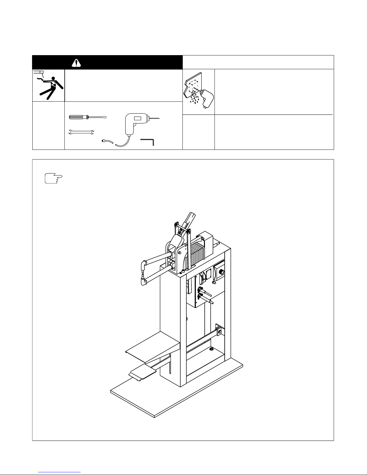
Figure 1. Assembled SWP-2 (MSW Spot Welder And Timer Illustrated)
ST-800 203
© 2007 MILLER Electric Mfg. Co.
Part
Item
No.
No.
1 023 937 Pedal (1)
2 023 933 Extension Spring (1)
3 023 940 Case (1)
4 605 394 Cotter Pin, 1/8 x 3/4 (2)
5 010 910 Washer, 3/8 flat (7)
6 024 292 Clevis Pin (1)
7 023 989 Pedestal Base (1)
8 601 865 Nut, 1/4-20 (7)
9 602 207 Washer, 1/4 lock (11)
10 602 125 Screw, 1/4-20 x 1 (4)
11 023 936 Hook Bolt (1)
12 024 852 Collar, 11/32 x 3/4 x 7/16 (1) (Includes)
605 395 Set Screw, 8-32 x 3/16 (1)
171 187 No. 6 Steel Shot (1)
13 018 606 Spring (1)
14 024 851 Collar, 21/64 x 3/4 x 7/16 (1) (Includes)
602 177 Set Screw, 1/4-20 x 1/4 (1)
15 024 140 Collar, 21/64 x 3/4 x 7/16 (1) (Includes)
602 177 Set Screw, 1/4-20 x 1/4 (2)
16 023 932 Compression Spring (1)
17 010 954 Washer, 1/8 x 1-1/4 flat (1)
18 601 869 Nut, 5/16-18 (2)
19 023 934 Pivot Lever Bracket (1)
20 128 237 Screw, 10-32 x 1/2 (1)
21 600 735 Ring Tongue Terminal (2)
22 602 203 Washer, No. 10 lock (3)
23 601 862 Nut, 10-32 (3)
24 136 718 Pedal Guard (1)
25 136 717 Support Strip (2)
26 604 224 Screw, 1/4-20 x 3/4 (5)
27 602 355 Cotter Pin, 3/32 x 1/2 (4)
28 024 134 Pivot Bracket (1)
29 023 945 Aircord Cable (1)
30 602 154 Screw, 10-32 x 5/8
31 024 136 U-Bolt (1)
32 602 154 Screw, 1/4-20 x 1/2
Description (Qty)
(part of spot welder) (1)
(2 part of timer) (4)
Part
For permanent installation, discard base
(7) and mount case directly to floor.
3
4
5
2
6
1
7
8
9
10
Be sure to provide Model when ordering replacement
parts.
OM-712 Page 2
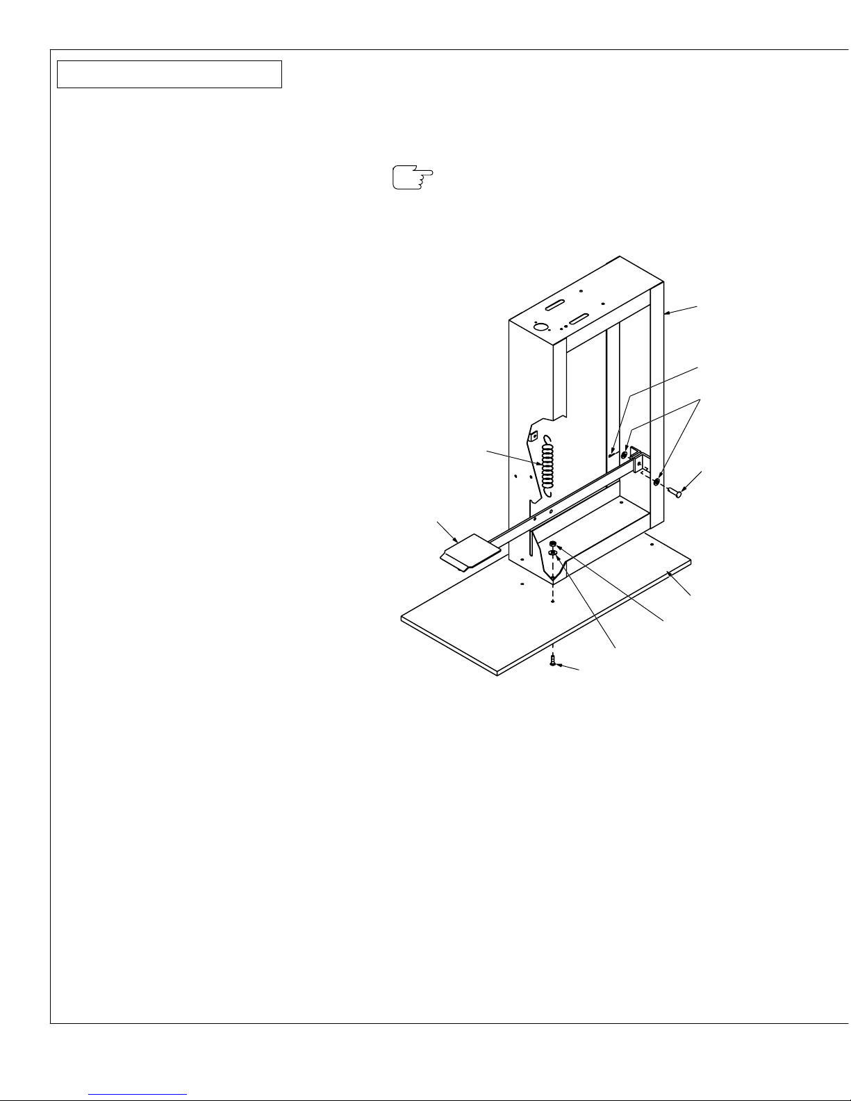
Assembly Instructions
1. Mount case (3) to base (7) using supplied hardware.
2. Secure foot pedal (1) to case using supplied hardware.
3. Connect spring (2) to foot pedal and case.
Figure 2. Installing SWP-2
 Loading...