

Specifications and Main Features
- Models: Auto ARC® MW 4150, Auto ARC® MW 4200, SPW-1
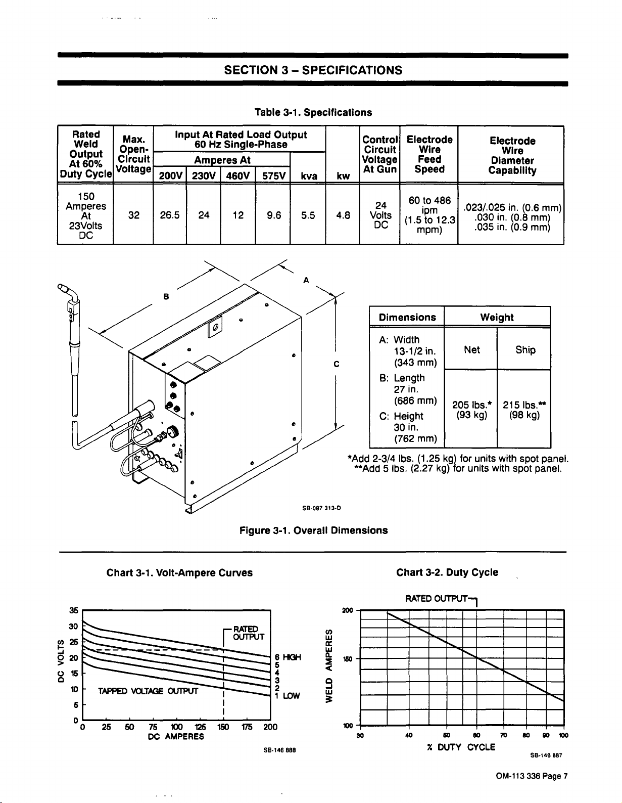
- Rated Output: 150 ampere
- Voltage Settings: 230V, 460V, 575V
- Duty Cycle: 60% at rated output and 40% at 275 A output.
- Weight: 205lbs (net), 215lbs (ship)
- Dimensions:
- Vertical tube diameter: 238 mm.
- Vertical tube height: 937 mm.
- Vertical tube (length) huh):(measurement: 409 mm.
- Wall Receptacle: 200/230 volt models only
- Voltage Input Requirements: Single-phase, 60Hz, same as electric input voltage on Nameplate of the unit.
- Shielding Gas Types: Carbon Dioxide (CO2)or a mixture of 75 percent argon and 25 percent CO2
- Wire Feed Speed Control: Throttle control
- Welding Process Capabilities: Shielded metal arc welding with both short circuit and spray transfer.
- Fan-On-Demand™ Cool Down System: Cooling system that uses a thermostat to regulate temperatures.
- Operator Controls: Power-switch ,voltage selector and fine var speed control.
- Safety Features: Overload protection and thermal protection circuits.
---
Frequently Asked Questions
Q: What welding processes can be done using the Auto ARC models?
A: The welding processes supported by Auto ARC models include GMAW based on both short circuit and spray transfer GMAW.
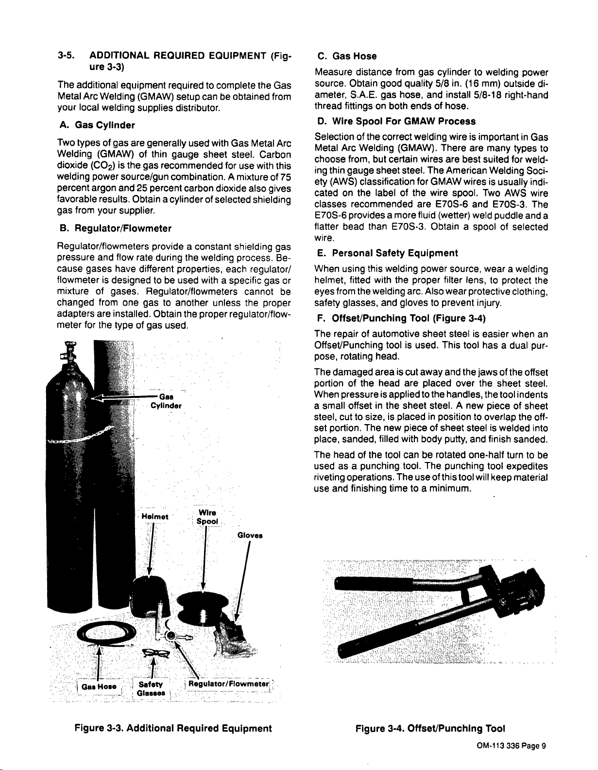
Q: What shielding gases are appropriate for use with this welding power source?
A: The most suitable shielding gas to be used can be either carbon dioxide gas or a mix of e75% argon and 25% carbon dioxide gas.
Q: What maximum duty cycle can the Auto ARC models achieve?
A: For every 150 amperes run in these units, the amperes rating can reach a maximum of 60%.
Q: What is the size of the devices?
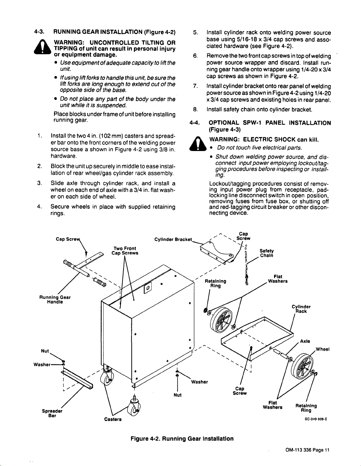
A: The running gear is provided with the units and they are somewhat mobile but they should not be roughly moved around during transportation.
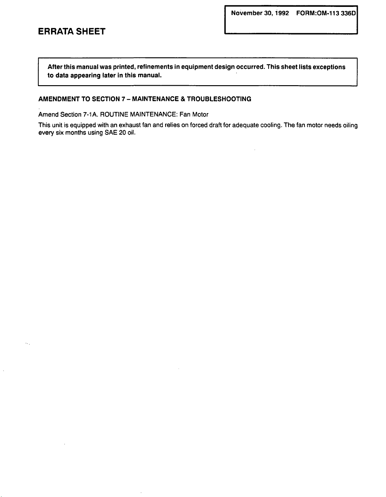
Q: What does the maintenance of the fan motor comprise of?
A: There is no need for particular maintenance of the fan motor except conducting a source cleaning of dust and dirty indoors in every half year.
Q: Untoward overheating events how do I address them?
A: Look for wire bindings, blockages in the gun liner, or blockages in fan vents. Should thermal overload have happened then let the machine cushion itself for a time before straining it.
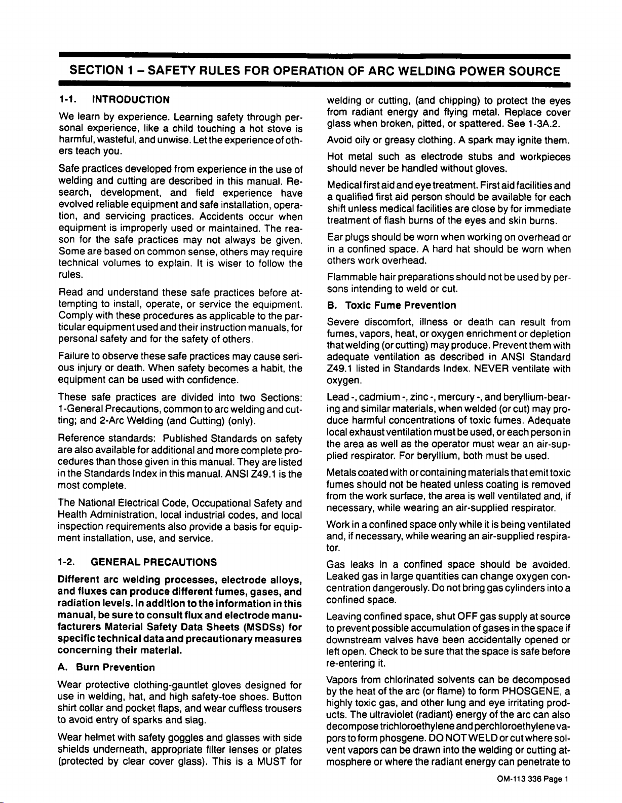
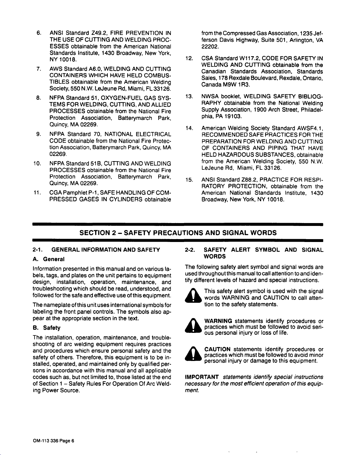
Q: Is it required to wear protective clothing for the welding unit?
A: Yes, appropriate safety apparel, gloves, and a welding helmet with the correct lenses should always be worn when working with the unit.
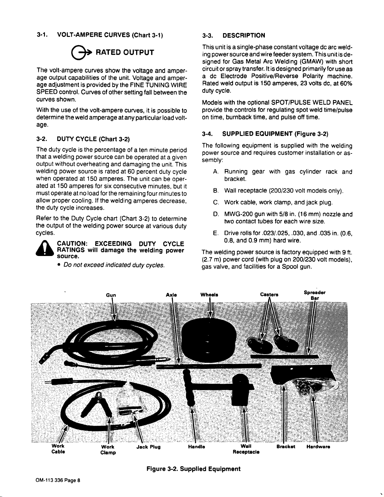
Q: How much does all of the equipment together weigh?
A: On a net term, the weight will be around 205 while in circumstances of shipping, the weight is roughly 215.
Q: In what ways can I alter the speed of the wire feed?
A: On the control panel of the operator’s device, the Fine Tuning Wire Speed Control will allow the operator to adjust for the requirements.
Q: Who sells replacement parts?
A: Local welding supplies distributors or authorized service locations are where you would go to get the replacement parts for the necessary items.
User Manual


 Loading...