

Miller Electric SGA 100, SGA 100C Owner's Manual
Owner’s Manual
SGA 100 And SGA 100C
1. Safety Symbol Definitions
June 2000 FORM: OM-190 753F
Use above FORM number when ordering extra manuals.
Warning! Watch Out! There are possible hazards as
shown in the adjoining symbols.
Beware of electric shock from wiring. Turn Off welding
power source and disconnect power before installing this
kit. Reinstall all panels and covers.
Wear safety glasses with side shields.
NOTE
The SGA 100 and SGA 100C are not required for use with the Millermatic 185 and
IronMan 210 models, and IronMan 250 models effective with serial no. LA135884
Have only trained and qualified persons install, operate,
or service this unit. Call your distributor if you do not understand the directions. For WELDING SAFETY and
EMF information, read welding power source Owner’s
Manual.
Hot parts can cause burns. Welding makes parts very hot
− let them cool before touching.
and following).
2. Weld Control Specifications
Specification
Input Power Single-Phase 115 Volts AC, .5 Amperes, 60 Hertz
Control Circuit Voltage Provided To Spool Gun 36 Volts DC
Welding Power Source Type Constant Voltage (CV) DC, With or Without Contactor
Connections Gun Trigger Controls, Gas And Weld Cables
Welding Process DC Gas Metal Arc Welding (GMAW)
Input Power Cord With Plug 10 ft (3 m)
Overall Dimensions SGA 100: 13 in (330 mm) L x 8 in (203 mm) W x 5 in (127 mm) H
Weight SGA 100: 10 lb (4.5 kg); SGA 100 C: 13 lb (5.9 kg)
SGA 100C: 13 in (330 mm) L x 8 in (203 mm) W x 9 in (229 mm) H
3. Duty Cycle
Maximum rating for the SGA 100
and SGA 100C is 150 amperes at a
60% duty cycle.
Duty Cycle is percentage of 10 mi n utes that unit can weld at rated load
6 Minutes Welding 4 Minutes Resting
without overheating.
NOTE: If you are connecting this spoolgun adapter to a unit with an output contactor, proceed to Section 4. If you are
connecting this spoolgun adapter to a unit without an output contactor, proceed to Section 5.
2000 MILLER Electric Mfg. Co.
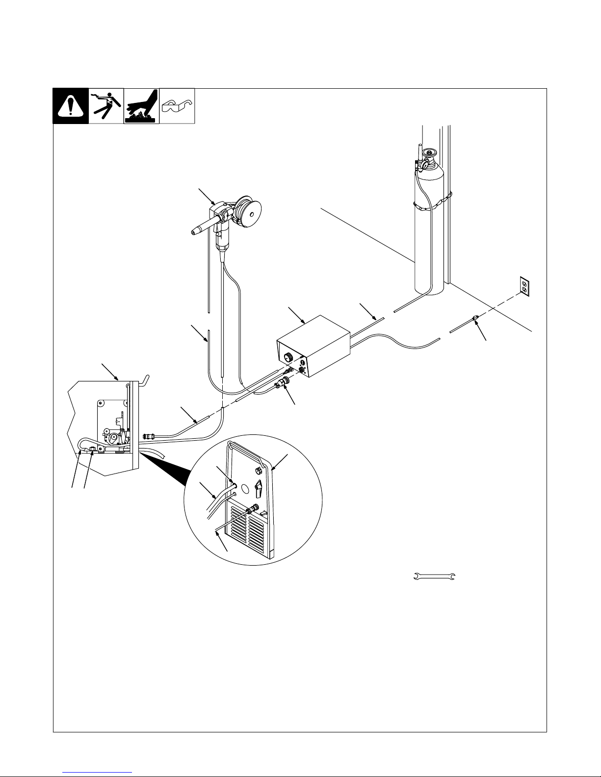
4. Installing SGA 100 Spoolmate Adapter (Kit 043 856)
A. Making Connections To Units With An Output Contactor (Millermatic 185 And IronMan 210 Models, And
IronMan 250 Models Effective With Serial No. LA135884 And Following Do Not Require This Accessory)
.Drawing shows typical welding
power source installation.
1
2
9
3
8
6
7
7
4
8
10
5
11
12
Tools Needed:
3/4 in
Y Turn Off and disconnect input
power.
1 Spoolmate 185 Or Spoolmate 250
2 SGA 100 Control Box
3 Welding Power Source With 1/2 in
(13 mm) Weld Cable Stud
4 1/2 in (13 mm) Weld Cable Stud
5 Front Panel
6 Front Panel Opening
7 Spoolgun Weld Cable
Route Spoolgun weld cable through front
panel opening and connect to 1/2 in (13
OM-190 753 Page 2
mm) weld cable stud. NOTE: if unit does
not have a 1/2 in (13 mm) weld cable stud,
proceed to Section 3B
8 Interconnecting Cord
Connect interconnecting cord as shown.
NOTE: a second interconnecting cord with
female friction terminals on each end (not
shown) is p r o v i d e d w ith this kit. If your unit
requires this type of interconnecting cord,
connect female friction terminals to matching male friction terminals on front panels of
welding power source and SGA 100 control box. Polarity is not important.
9 Spoolgun Gas Hose
Slide spoolgun gas hose onto barbed fitting
on SGA 100 control box where shown.
10 Spoolgun Trigger Control Plug
Connect spoolgun trigger control plug to
matching receptacle on SGA 100 control
box where shown.
11 Gas Hose
Slide gas hose onto fitting on back of SGA
100 control box.
12 115 VAC Plug
Connect plug as shown.
Ref. ST-802 181
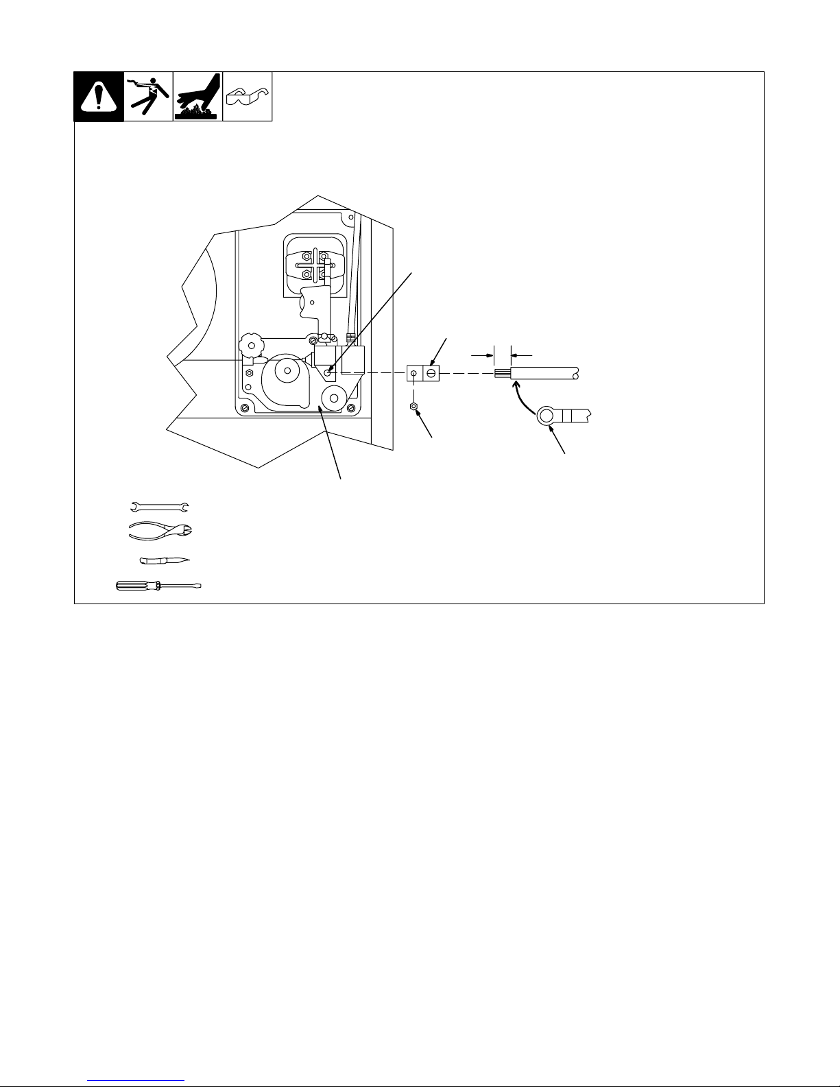
B. Connecting Spoolmate Spoolgun Weld Cable To Units Without A 1/2 in Weld Cable Stud
Tools Needed:
5/16 in
.Drawing shows typical welding
power source installation.
2
3
1
1 Wire Drive Assembly
2 Gun Securing Bolt
3 Gun Securing Nut
Remove gun securing nut.
4 Terminal
Slide terminal onto gun securing bolt
and secure with gun securing nut.
5 Spoolgun Weld Cable Ring
Terminal
Cut off ring terminal and strip insulation back 1/2 in (13 mm).
Slide spoolgun weld cable into terminal 1/2 in (13 mm). Tighten setscrew.
Go back to Section 3A, Item 8, to
complete the installation.
4
1/2 in
5
Ref. ST-802 181
OM-190 753 Page 3
 Loading...