

Miller Electric SCE-1A, SCE-5A, SCE-3A, SCM-1A, SCM-3A Owner's Manual
...
February
1980
FORM:
OM-540A
.tcc
._
,
I.
~
5
Effective
With
Serial
No.
HK321565
MODEL
SCE-1A
SCE-3A
SCE-5A
SCM-lA
SCM-3A
SCM-5A
OWN
E
RS
MANUAL
I11dIER
MILLER
ELECTRIC
MFG.
CO.
718
S.
BOUNDS
ST.
P.O.
Box
1079
APPLETON,
WI
54912
USA
NWSA
CODE
NO.
4579
PRINTED
IN
U.S.A.

L~
~L~
L
~
L&P
~
LIMITED
WARRANTY
EFFECTIVE:
JUNE
1.
1979
This
warranty
supersedes
all
previous
MILLER
warranties
and
is
ex
clusive
with
no
other
guarantees
or
warranties
expressed
or
implied.
LIMITED
WARRANTY-Subject
to
the
terms
and
conditions
As
a
matter
of
general
policy
on1y,
Miller
may
honor
claims
hereof,
Miller
Electric
Mfg.
Co.,
Appleton,
Wisconsin
warrants
submitted
by
the
original
user
within
the
foregoing
periods.
to
its
Distributor/Dealer
that
all
new
and
unused
Equipment
(
furnishedbyMiller
is
free
from
defect
in
workmanship
and
In
the
case
of
Millers
breach
of
warranty
or
any
other
duty
materialasof
the
time
and
placeofdelivery
by
Miller.
No
war-
with
respect
to
the
quality
of
any
goods,
the
exclusive
remedies
ranty
is
made
by
Miller
with
respect
to
engines,
trade
ac-
therefore
shall
be,
at
Millers
option
11)
repair
or
(21
replacement
cessories
or
other
items
manufactured
by
others.
Such
or,
where
authorized
in
writing
by
Miller
in
appropriate
cases,
(31
engines,
trade
accessories
and
other
items
are
sold
subject
to
the
reasonable
cost
of
repair
or
replacement
at
an
authorized
the
warranties
of
their
respective
manufacturers,
if
any
.
All
Miller
service
station
or
141
payment
of
or
credit
for
the
purchase
engines
are
warranted
by
their
manufacturer
for
one
year
from
price
(less
reasonable
depreciation
based
upon
actual
use)
upon
date
of
original
purchase.
return
of
the
goods
at
Customers
risk
and
expense.
Upon
receipt
of
notice
of
apparent
defect
or
failure,
Miller
shall
instruct
the
clai-
Except
as
specified
below,
Millers
warranty
does
not
apply
mant
on
the
warranty
claim
procedures
to
be
followed.
to
components
having
normal
useful
lifeofless
than
one
(1)
year,
such
as
spot
welder
tips,
relay
and
contactor
points,
ANY
EXPRESS
WARRANTY
NOT
PROVIDED
HEREIN
AND
MILLERMATIC
parts
that
come
in
contact
with
the
welding
ANY
IMPLIED
WARRANTY,
GUARANTY
OR
REPRESENTA-
wire
including
nozzles
and
nozzle
insulators
where
failure
does
lION
AS TO
PERFORMANCE,
AND
ANY
REMEDY
FOR
not
result
from
defect
in
workmanship
or
material.
BREACH
OF
CONTRACT
WHICH,
BUT
FOR
THIS
PROVISION,
MIGHT
ARISE
BY
IMPLICATION,
OPERATION
OF
LAW,
Miller
shall
be
required
to
honor
warranty
claims
on
war-
CUSTOM
OF
TRADE
OR
COURSE
OF
DEALING,
INCLUDING
ranted
Equipment
in
the
event
of
failure
resulting
from
a
defect
ANY
IMPLIED
WARRANTY
OF
MERCHANTABILITY
OR
OF
within
the
following
periods
from
the
date
of
deliveryofEquip-
FITNESS
FOR
PARTICULAR
PURPOSE,
WITH
RESPECT
TO
ment
to
the
original
user:
ANY
AND
ALL
EQUIPMENT
FURNISHED
BY
MILLER
(S
EX
CLUDED
AND
DISCLAIMED
BY
MILLER.
1.
Arc
welders,
power
sources
and
components
-
.
1
year
2.
Original
main
power
rectifiers
3
years
EXCEPT
AS
EXPRESSLY
PROVIDED
BY
MILLER
IN
(labor
-
1
year
onlyl
WRITING,
MILLER
PRODUCTS
ARE
INTENDED
FOR
3.
All
welding
guns
and
feeder/guns
90
days
ULTIMATE
PURCHASE
BY
COMMERCIAL/INDUSTRIAL
4.
All
other
Millermatic
Feeders
1
year
USERS
AND
FOR
OPERATION
BY
PERSONS
TRAINED
AND
5.
Replacement
or
repair
parts,
exclusive
of
labor
.
60
days
EXPERIENCED
IN
THE
USE
AND
MAINTENANCE
OF
6.
Batteries
6
months
WELDING
EQUIPMENT
AND
NOT
FOR
CONSUMERS
OR
CONSUMER
USE.
MILLER
WARRANTIES
DO
NOT
EXTEND
provided
that
Miller
is
notified
in
writing
within
thirty
(30)
days
TO,
AND
NO
RESELLER
IS
AUTHORIZED
TO
EXTEND
of
the
date
of
such
failure.
MILLERS
WARRANTIES
TO,
ANY
CONSUMER.
~%
.~,
J~
~
J~
TABLE
OF
CONTENTS
Section
No.
Page
No.
SECTION
1
INTRODUCTION
1
-
1.
General
1
1
-
2.
Receiving-Handling
1
1
-
3.
Description
1
1-4.
Safety
1
SECTION
2INSTALLATION
2-
1.
Electrical
Input
Connections
1
2.
2.
Secondary
Connections
1
2
-
3.
Shielding
Gas
Con
nØctions
1
2
-
4.
Coolant
Connections
2
2
-
5.
Contactor
Control
Receptacle
2
2.
6.
Emergency
Stop
Switch
Connections
2
2-
7.
Manual
Control
Connections
Of
Sequence
C
2
SECTION
3
FUNCTION
OF
CONTROLS
3
-
1.
Sequence
Control
Function
3
3-
2.
Current
Control
3
3
-
3.
Start
Switch
(SCE/SCM-1A
and
2A)
3
3
-
4.
Weld
Switch
3
3
-
5.
Manual
Control
Of
Sequence
C
4
3-
6.
High-Frequency
Control
4
SECTION
4
SEQUENCE
OF
OPERATION
4
-
1.
Gas
Tungsten-Arc
Welding
(GTAW)
4
4-
2.
Shielded
Metal-Arc
Welding
(SMAW)
4
4
-
3.
Shutting
Down
5
SECTION
5
MAINTENANCE
5
-
1.
High
Voltage
Capacitors
5
5-
2.
Spark
Gap
Adjustment
5
5-3.
Bypass
Panel
6
5
-
4.
Control
Circuit
Protection
6
SECTION
6
TROUBLESHOOTING
SECTION
7
CERTIFICATION
FOR
HIGH
FREQUENCY
ARC
WELDING
EQUIPMENT
7-
1.
General
7
7
-
2.
General
Information
7
7
-
3.
Power
Service
7
7
-
4.
Welding
Machine
7
7
-
5.
Welding
Leads
8
7
-
6.
Wiring
In
The
Vicinity
Of
The
Welding
Area
8
7-
7.
Grounds
8
7
-
8.
Metal
Building
8
7
-
9.
Individual
Installation
Certification
9
7-10.
Check
List
9

SECTION
1
-
INTRODUCTION
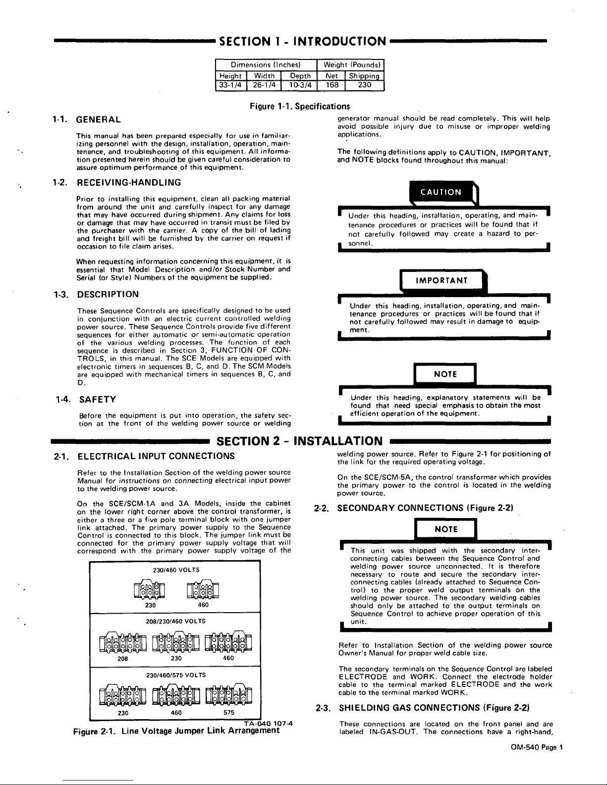
Dime
Height
nsions
(Inches)
Width
Depth
Weight
Net
(Pounds)
Shipping
33-1/4
26-1/4
10-3/4
168
230
Figure
1-1.
Specifications
1-1.
GENERAL
This
manual
has
been
prepared
especially
for
use
in
familiar
izing
personnel
with
the
design,
installation
operation,
main
tenance,
and
troubleshooting
of
this
equipment.
All
informa
tion
presented
herein
should
be
given
careful
consideration
to
assure
optimum
performance
of
this
equipment.
1-2.
RECEIVING-HANDLING
Prior
to
installing
this
equipment,
clean
all
packing
material
from
around
the
unit
and
carefully
inspect
for
any
damage
that
may
have
occurred
during
shipment.
Any
claims
for
loss
or
damage
that
may
have
occurred
in
transit
must
be
filed
by
the
purchaser
with
the
carrier.
A
copy
of
the
bill
of
lading
and
freight
bill
willbefurnished
by
the
carrier
on
request
if
occasion
to
file
claim
arises.
When
requesting
information
concerning
this
equipment,
it
is
essential
that
Model
Description
and/or
Stock
Number
and
Serial
(or
Style)
Numbers
of
the
equipment
be
supplied.
1-3.
DESCRIPTION
These
Sequence
Controls
are
specifically
designed
to
be
used
in
conjunction
with
an
electric
current
controlled
welding
power
source.
These
Sequence
Controls
provide
five
different
sequences
for
either
automatic
or
semi-automatic
operation
of
the
various
welding
processes.
The
function
of
each
sequence
is
described
in
Section
3,
FUNCTION
OF
CON
TROLS,
in
this
manual.
The
SCE
Models
are
equipped
with
electronic
timers
in
sequences
B,
C,
andD.The
SCM
Models
are
equipped
with
mechanical
timers
in
sequences
B,
C,
and
D.
1-4.
SAFETY
Before
the
equipment
is
put
into
operation,
the
safety
sec
tion
at
the
frontofthe
welding
power
source
or
welding
generator
manual
should
be
read
completely.
This
will
help
avoid
possible
injury
due
to
misuse
or
improper
welding
applications.
The
following
definitions
apply
to
CAUTION,
IMPORTANT,
and
NOTE
blocks
found
throughout
this
manual:
sonnel.
I
IL
1
U
.
Under
this
heading,
installation,
operating,
and
main
tenance
procedures
or
practices
will
be
found
that
if
not
carefully
followed
may
result
in
damagetoequip
ment.
NOTE
Under
this
heading,
explanatory
statements
will
be
found
that
need
special
emphasis
to
obtain
the
most
efficient
operation
of
the
equipment.
SECTION
2
-
INSTALLATION
2-1.
ELECTRICAL
INPUT
CONNECTIONS
Refertothe
Installation
Section
of
the
welding
power
source
Manual
for
instructions
on
connecting
electrical
input
power
to
the
welding
power
source.
On
the
SCE/SCM-1A
and
3A
Models,
inside
the
cabinet
on
the
lower
right
corner
above
the
control
transformer,
is
either
a
three
or
a
five
pole
terminal
block
with
one
jumper
link
attached.
The
primary
power
supply
to
the
Sequence
Control
is
connected
to
this
block.
The
jumper
link
must
be
connected
for
the
primary
power
supply
voltage
that
will
correspond
with
the
primary
power
supply
voltage
of
the
TA-040
107-4
Figure
2-1.
Line
Voltage
Jumper
Link
Arrangement
welding
power
source.
Refer
to
Figure
2-1
for
positioning
of
the
link
for
the
required
operating
voltage.
On
the
SCE/SCM-5A,
the
control
transformer
which
provides
the
primary
power
to
the
controlislocatedinthe
welding
power
source.
2-2.
SECONDARY
CONNECTIONS
(Figure
2-2)
unit
was
shipped
wh
the
secondary
inte
r
connecting
cables
between
the
Sequence
Control
and
welding
power
source
unconnected.
It
is
therefore
necessary
to
route
and
secure
the
secondary
inter
connecting
cables
(already
attached
to
Sequence
Con
trol)
to
the
proper
weld
output
terminals
on
the
welding
power
source.
The
secondary
welding
cables
should
only
be
attached
to
the
output
terminals
on
Sequence
Controltoachieve
proper
operation
of
this
Refer
to
Installation
Sectionofthe
welding
power
source
Owners
Manual
for
proper
weld
cable
size.
The
secondary
terminalsonthe
Sequence
Control
are
labeled
ELECTRODE
and
WORK.
Connect
the
electrode
holder
cable
to
the
terminal
marked
ELECTRODE
and
the
work
cable
to
the
terminal
marked
WORK.
2-3.
SHIELDING
GAS
CONNECTIONS
(Figure
2-2)
These
connections
are
located
on
the
front
panel
and
are
labeled
IN-GAS-OUT.
The
connections
have
a
right-hand,
Under
this
heading,
installation,
operating,
and
main
tenance
procedures
or
practices
will
he
found
that
if
not
carefully
followed
may
create
a
hazard
to
per-
U
I
U
I
230/460
VOLTS
~
230
460
208/230/460
VOLTS
208
230
460
230/460/575
VOLTS
00
000
230
460
575
OM-540
Page
1
5/8-18
female
thread.
Connect
the
hose
from
the
shielding
gas
supply
to
the
connection
labeled
IN.
Connect
the
hose
from
the
electrode
holder
to
the
connection
labeled
OUT.
2-4.
COOLANT
CONNECTIONS
(Figure
2-2)
These
connections
are
located
on
the
front
panel
and
are
labeled
IN-COOLANT-OUT.
The
connections
have
a
left-
hand,
5/8-18
female
thread.
Connect
the
hose
from
the
coolant
supply
to
the
connection
labeled
IN.
Connect
the
hose
from
the
electrode
holder
to
the
connection
labeled
OUT.
This
three-prong,
twistlock
receptacle
provides
contactor
control
facilities.
Either
a
remote
hand
or
foot
switch
can
be
used
in
conjunction
with
this
receptacle.
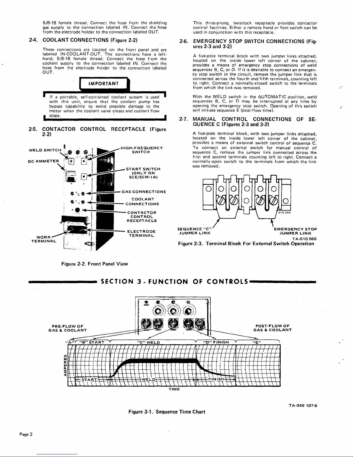
2-6.
EMERGENCY
STOP
SWITCH
CONNECTIONS
(Fig
ures
2-3
and
3-2)
A
five-pole
terminal
block
with
two
jumper
links
attached,
located
on
the
inside
lower
left
corner
of
the
cabinet,
provides
a
means
of
emergency
stop
connections
of
weld
sequences
B,
C,
or
0.
If
it
is
desirable
to
connect
an
emergen
cy
stop
switch
in
the
circuit,
remove
the
jumper
link
that
is
connected
across
the
fourth
and
fifth
terminals,
counting
left
to
right.
Connect
a
normally-closed
switch
to
the
terminals
from
which
the
link
was
removed.
If
a
portable,
self-contained
coolant
system
is
used
with
this
unit,
ensure
that
the
coolant
pump
has
bypass
capability
to
avoid
possible
damage
to
the
motor
when
the
coolant
valve
closes
and
coolant
flow
stops.
2-5.
CONTACTOR
CONTROL
RECEPTACLE
(Figure
2-2)
Figure
2-2.
Front
Panel
View
With
the
WELD
switch
in
the
AUTOMATIC
position,
weld
sequences
B,
C,
or
D
may
be
interrupted
at
any
time
by
opening
the
emergency
stop
switch.
Opening
of
this
switch
will
initiate
sequence
E
(post-flow
time).
2-7.
MANUAL
CONTROL
CONNECTIONS
OF
SE
QUENCE
C
(Figures
2-3
and
3-2)
A
five-pole
terminal
block,
with
two
jumper
links
attached,
located
on
the
inside
lower
left
corner
of
the
cabinet,
provides
a
means
of
external
switch
control
of
sequence
C.
To
connect
an
external
switch
for
manual
control
of
sequence
C,
remove
the
jumper
link
connected
across
the
first
and
second
terminals
counting
left
to
right.
Connect
a
normally-open
switch
to
the
terminals
from
which
the
link
was
removed.
SECTION
3-
FUNCTION
OF
CONTROLS
WELD
SWITCH
~
~
$
I
DC
AMMETER
~
L~
WORK
TERMINAL
HIGH-FREQUENCY
SWITCH
START
SWITCH
(ONLY
ON
SCE/SCM-1
A)
GAS
CONNECTIONS
COOLANT
CONNECTIONS
CONTA
CTO
R
CONTROL
RECEPTACLE
ELECTRODE
TERMINAL
TA-OlO
566
Figure
2-3.
Terminal
Block
For
External
Switch
Operation
PRE-FLOW
OF
ANT
GAS
&
Ui
CWFLD
Ui
a.
S
POST-FLOW
OF
GAS&COOLANT
DFINISH
~
E
~i~I77~ffl7~A
#~
~
~START
~
\~
~
FINISH
TIME
Figure
3-1.
Sequence
Time
Chart
TA-040
107-6
Page
2
3-1.
SEQUENCE
CONTROL
FUNCTION
(Figure
3-1)
This
Sequence
Control
is
a
five
sequence
automatic
control
designed
for
Gas
Tungsten-Arc
Welding
)GTAW).
The
function
of
each
sequence
is
as
follows:
PRE-FLOW:
gas
and
coolant;
adjustable
mechanical
time
of
1/4
to
15
seconds.
START
current:
adjustable
control
and
timer
preset
magnitude
of
current
and
time.
WELD
current:
adjustable
control
and
timer
provide
exact
values
of
current
and
time.
Sequence
can
be
manually
controlled.
Sequence
D:
SLOPE
current:
adjustable
control
and
timer
are
preset
to
determine
magnitude
and
time
duration
of
current
at
end
of
weld.
Sequence
E:
POST-F
LOW:
gas
and
coolant;
adjustable
mechanical
time
sequence
of
2
seconds
to
3
minutes.
3-2.
CURRENT
CONTROL
(Figure
3-2)
The
welding
current
for
sequences
B,
C.
and
D
is
governed
by
the
setting
of
the
control
immediately
above
each
sequence
timer.
These
controls
are
calibrated
in
percentages
and
function
as
remote
controls,
in
that
they
are
fine
amperage
adjustments
of
the
AMPERAGE
ADJUSTMENT
control
on
the
welding
power
source.
The
REMOTE
AMPERAGE
CONTROL
switch
on
the
welding
power
source
must
be
in
the
STANDARD
position
for
proper
operation
of
the
Sequence
Control.
NOTE
The
AMPERAGE
ADJUSTMENT
control
on
the
welding
power
source
must
beinthe
one
hundred
percent
(maximum)
position
for
maximum
control
of
the
selected
range.
value
from
the
minimum
to
the
maximum
of
the
selected
current
range
on
the
welding
power
source.
C.
Slope
Weld
Amperage
Control
(Sequence
D)
The
SLOPE
control
is
provided
for
selecting
the
slope
weld
current
value.
The
control
is
adjustable
and
can
be
set
for
any
value
from
the
minimum
to
the
maximum
of
the
selected
current
range
on
the
welding
power
source.
For
a
normal
finish
the
control
should
be
set
for
a
value
less
than
the
WELD
(sequence
C)
setting.
3-3.
START
SWITCH
(SCE/SCM-1A)
(Figure
2-2)
This
switch
provides
a
choice
of
selecting
either
a
normal
or
a
fast
start
of
sequence
B
(START
weld).
A.
Normal
Position
With
the
switch
in
the
NORMAL
position,
the
starting
current
will
start
at
a
value
less
than
the
setting
of
the
START
weld
amperage
control,
but
will
rapidly
increase
to
the
setting
of
the
START
weld
amperage
control.
B.
Fast
Position
With
the
switch
in
the
FAST
position,
the
starting
current
will
start
at
the
value
of
the
START
weld
amperage
setting.
3-4.
WELD
SWITCH
(Figure
2-2)
This
switch
provides
a
choice
of
selecting
either
an
automatic
or
semi-automatic
operation
of
the
Sequence
Control.
A.
Automatic
Position
With
the
switchinthe
AUTOMATIC
position,
the
Sequence
Control
will
operate
automatically
through
all
sequences
with
the
use
of
a
contactor
control
switch
connected
to
the
CONTACTOR
CONTROL
receptacle.
A.
Start
Weld
Amperage
Control
(Sequence
B)
The
START
control
is
provided
for
selecting
the
start
weld
current
value.
The
control
is
adjustable
and
can
be
set
for
any
value
from
the
minimum
to
the
maximum
of
the
selected
current
range
on
the
welding
power
source.
For
a
normal
start
the
control
should
be
set
foravalue
less
than
the
WELD
(sequence
C)
setting.
B.
Weld
Amperage
Control
(Sequence
C)
The
WELD
control
is
provided
for
selecting
the
normal
weld
current
value.
The
control
is
adjustable
and
can
be
set
for
any
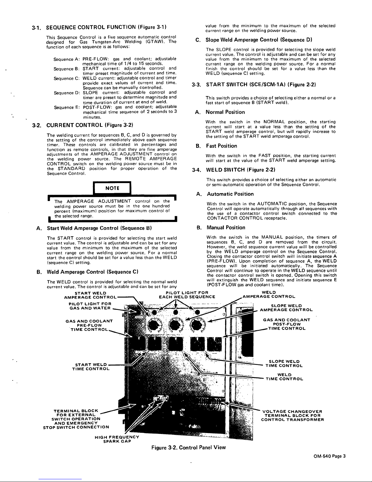
START
WELD
AMPERAGE
CONTROL
PILOT
LIGHT
FOR
GAS
AND
WATER
GAS
AND
COOLANT
PRE-FLOW
TIME
CONTROL.~~,
B.
Manual
Position
With
the
switch
in
the
MANUAL
position,
the
timers
of
sequences
B,
C,
and
D
are
removed
from
the
circuit.
However,
the
weld
sequence
current
value
will
be
controlled
by
the
WELD
amperage
control
on
the
Sequence
Control.
Closing
the
contactor
control
switch
will
initiate
sequence
A
)PRE-FLOW).
Upon
completion
of
sequence
A,
the
WELD
sequence
will
be
initiated
automatically.
The
Sequence
Control
will
continue
to
operate
in
the
WELD
sequence
until
the
contactor
control
switch
is
opened.
Opening
this
switch
will
extinguish
the
WELD
sequence
and
initiate
sequence
E
(POST-FLOW
gas
and
coolant
time).
SLOPE
WELD
1
AMPERAGE
CONTROL
GAS
AND
COOLANT
POST-FLOW
CONTROL
2
SLOPE
WELD
TIME
CONTROL
WELD
.T!~TIME
CONTROL
VOLTAGE
CHANGEOVER
TERMINAL
BLOCK
FOR
CONTROL
TRANSFORMER
Sequence
A:
Sequence
B:
Sequence
C:
PILOT
LIGHT
FOR
WELD
EACH
WELD
SEQUENCE
AMPERAGE
CONTROL
START
WELD
TIME
CONTROL
TERMINAL
BLOCK
FOR
EXTERNAL
SWITCH
OPERATION
AND
EMERGENCY
STOP
SWITCH
CONNECTION
I.
HIGH
FREQUENCV
SPARK
GAP
Figure
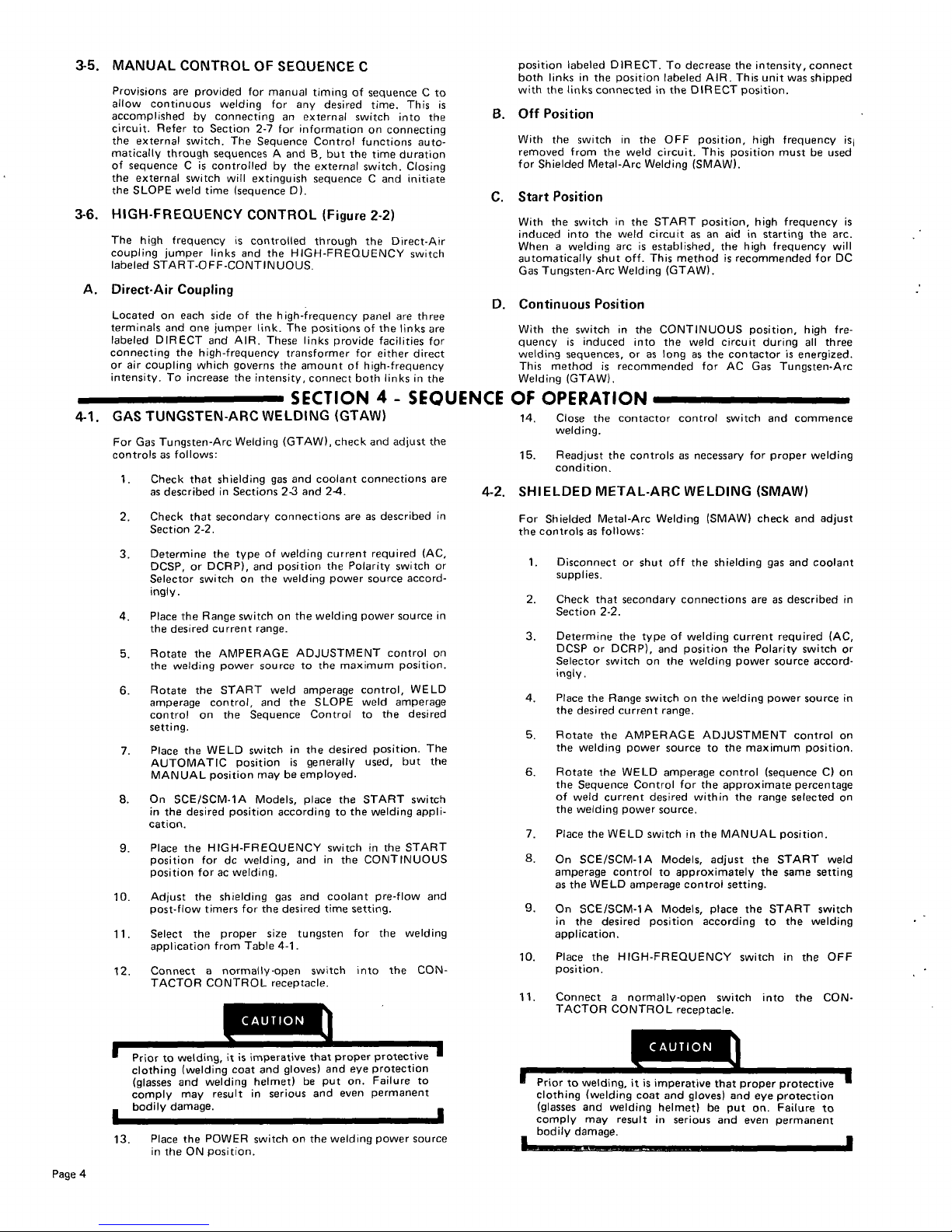
3-2.
Control
Panel
View
OM-540
Page
3
3-5.
MANUAL
CONTROL
OF
SEQUENCE
C
Provisions
are
provided
for
manual
timing
of
sequence
C
to
allow
Continuous
welding
for
any
desired
time.
This
is
accomplished
by
connecting
an
external
switch
into
the
Circuit.
Refer
to
Section
2-7
for
information
on
connecting
the
external
switch.
The
Sequence
Control
functions
auto
matically
through
sequences
A
andB,but
the
time
duration
of
sequence
C
is
controlled
by
the
external
switch.
Closing
the
external
switch
will
extinguish
sequence
C
and
initiate
the
SLOPE
weld
time
(sequence
DL
3-6.
HIGH-FREQUENCY
CONTROL
(Figure
2-2)
The
high
frequency
is
controlled
through
the
Direct-Air
coupling
jumper
links
and
the
HIGH-FREQUENCY
switch
labeled
START-OFF-CONTINUOUS.
A.
Direct-Air
Coupling
Located
on
each
side
of
the
high-frequency
panel
are
three
terminals
and
one
jumper
link.
The
positions
of
the
links
are
labeled
DIRECT
and
AIR.
These
links
provide
facilities
for
connecting
the
high-frequency
transformer
for
either
direct
or
air
coupling
which
governs
the
amount
of
high-frequency
intensity.
To
increase
the
intensity,
connect
both
links
in
the
SECTION
4
-
SEQUENCE
4-1.
GAS
TUNGSTEN-ARC
WELDING
(GTAW)
For
Gas
Tungsten-Arc
Welding
(GTAW(.
check
and
adjust
the
controls
as
follows:
1.
Check
that
shielding
gas
and
coolant
connections
are
as
described
in
Sections
2-3
and
2-4.
2.
Check
that
secondary
connections
are
as
described
in
Section
2-2.
3.
Determine
the
type
of
welding
current
required
(AC,
DCSP,
or
DCRP(,
and
position
the
Polarity
switch
or
Selector
switch
on
the
welding
power
source
accord
ingly.
4.
Place
the
Range
switchonthe
welding
power
source
in
the
desired
current
range.
5.
Rotate
the
AMPERAGE
ADJUSTMENT
control
on
the
welding
power
source
to
the
maximum
position.
6.
Rotate
the
START
weld
amperage
control,
WELD
amperage
control,
and
the
SLOPE
weld
amperage
control
on
the
Sequence
Control
to
the
desired
setting.
7.
Place
the
WELD
switch
in
the
desired
position.
The
AUTOMATIC
position
is
generally
used,
but
the
MANUAL
position
may
be
employed.
8.
On
SCE/SCM-1A
Models,
place
the
START
switch
in
the
desired
position
according
to
the
welding
appli
cation.
9.
Place
the
HIGH-FREQUENCY
switch
in
the
START
position
for
dc
welding,
and
in
the
CONTINUOUS
position
for
ac
welding.
10.
Adjust
the
shielding
gas
and
coolant
pre-flow
and
post-flow
timers
for
the
desired
time
setting.
11.
Select
the
proper
size
tungsten
for
the
welding
application
from
Table
4-1.
12.
Connect
a
normally-open
switch
into
the
CON
TACTOR
CONTROL
receptacle.
to
welding,
it
is
imperative
that
proper
protective
clothing
(welding
coat
and
gloves)
and
eye
protection
(glasses
and
welding
helmet)
be
put
on.
Failure
to
comply
may
result
in
serious
and
even
permanent
bodily
damage.
position
labeled
DIRECT.
To
decrease
the
intensity,
connect
both
links
in
the
position
labeled
AIR.
This
unit
was
shipped
with
the
links
connectedinthe
DIRECT
position.
B.
Off
Position
With
the
switch
in
the
OFF
position,
high
frequency
is1
removed
from
the
weld
circuit.
This
position
must
be
used
for
Shielded
Metal-Arc
Welding
(SMAW).
C.
Start
Position
With
the
switch
in
the
START
position,
high
frequency
is
induced
into
the
weld
circuit
as
an
aid
in
starting
the
arc.
When
a
welding
arc
is
established,
the
high
frequency
will
automatically
shut
off.
This
methodisrecommended
for
DC
Gas
Tungsten-Arc
Welding
(GTAW).
D.
Continuous
Position
With
the
switch
in
the
CONTINUOUS
position,
high
fre
quency
is
induced
into
the
weld
circuit
during
all
three
welding
sequences,
or
as
long
as
the
contactor
is
energized.
This
method
is
recommended
for
AC
Gas
Tungsten-Arc
Welding
(GTAW).
OF
OPERATION
14.
Close
the
contactor
control
switch
and
commence
welding.
15.
Readjust
the
controls
as
necessary
for
proper
welding
condition.
4-2.
SHIELDED
METAL-ARC
WELDING
(SMAW)
For
Shielded
Metal-Arc
Welding
(SMAW)
check
and
adjust
the
controls
as
follows:
1.
Disconnect
or
shut
off
the
shielding
gas
and
coolant
supplies.
2.
Check
that
secondary
connections
are
as
described
in
Section
2-2.
3.
Determine
the
type
of
welding
current
required
(AC,
DCSP
or
DCRP),
and
position
the
Polarity
switch
or
Selector
switch
on
the
welding
power
source
accord
ingly.
4.
Place
the
Range
switch
on
the
welding
power
source
in
the desired
current
range.
5.
Rotate
the
AMPERAGE
ADJUSTMENT
control
on
the
welding
power
source
to
the
maximum
position.
6.
Rotate
the
WELD
amperage
control
(sequence
C)
on
the
Sequence
Control
for
the
approximate
percentage
of
weld
current
desired
within
the
range
selected
on
the
welding
power
source.
7.
Place
the
WELD
switchinthe
MANUAL
position.
8.
On
SCE/SCM-1A
Models,
adjust
the
START
weld
amperage
control
to
approximately
the
same
setting
as
the
WELD
amperage
control
setting.
9.
On
SCEISCM-1A
Models,
place
the
START
switch
in
the
desired
position
according
to
she
welding
application.
10.
Place
the
HIGH-FREQUENCY
switch
in
the
OFF
position.
11.
Connect
a
normally-open
switch
into
the
CON
TACTOR
CONTROL
receptacle.
to
welding,
it
is
impera
ye
that
proper
protective
clothing
(welding
coat
and
gloves)
and
eye
protection
(glasses
and
welding
helmet)
be
put
on.
Failure
to
comply
may
result
in
serious
and
even
permanent
bodily
damage.
I
13.
Place
the
POWER
switch
on
the
welding
power
source
in
the
ON
position.
Page
4
 Loading...