

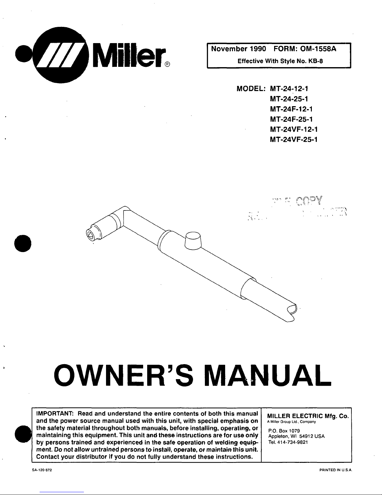
Miller Electric MT-24-12-1, MT-24-25-1, MT-24 F-25-1, MT-24VF-12-1, MT-24F-1 2-1 Owner's Manual
...
I,
Millerfi
November
1990
FORM:
OM-1558A
Effective
With
Style
No.
KB-8
MODEL:
MT-24-12-1
MT-24-25-1
MT-24F-1
2-1
MT-24
F-25-1
MT-24VF-12-1
MT-24VF-25-1
OWNERS
MANUAL
IMPORTANT:
Read
and
understand
the
entire
contents
of
both
this
manual
and
the
power
source
manual
used
with
this
unit,
with
special
emphasis
on
the
safety
material
throughout
both
manuals,
before
installing,
operating,
or
maintaining
this
equipment.
This
unit
and
these
instructions
are
for
use
only
by
persons
trained
and
experienced
in
the
safe
operationofwelding
equip
ment.
Do
not
allow
untrained
persons
to
install,
operate,
or
maintarn
this
unit.
Contact
your
distributor
if
you
do
not
fully
understand
these
instructions.
MILLER
ELECTRIC
Mfg.
Co.
A
Miller
Group
Ltd.,
Company
P.O.
Box
1079
Appleton,
WI
54912
USA
Tel.
414-734-9821
..,,n~
SA-120
672
PRINTED
IN
U.S.A.
LIMITED
WARRANTY
EFFECTIVE:
AUGUST
6,
1990
lii
This
warranty
supersedes
all
previous
MILLER
warranties
andisexclusive
with
no
dther
guarantees
or
warranties
expressed
or
implied.
LIMITED
WARRANTY
Subject
to
the
terms
and
conditions
hereof,
MILLER
Electric
Mfg.
Co.,
Appleton,
Wisconsin
war
rants
to
its
Distributor/Dealer
that
all
new
and
unused
Equipment
furnished
by
MILLER
is
free
from
defect
in
workmanship
and
material
as
of
the
time
and
place
of
delivery
by
MILLER.
No
warranty
is
made
by
MILLER
with
respect
to
engines,
trade
accessories
or
other
items
manufactured
by
others,
Such
engines,
trade
accessories
and
other
items
are
sold
subject
to
the
warranties
of
their
respective
manufacturers,
if
any.
All
engines
are
warrant
ied
by
their
manufacturer
for
two
years
from
date
of
original
purchase,
except
Deutz
engines
which
have
a
one
year,
2000
hour
warranty.
Exceptasspecified
below,
MILLERs
warranty
does
not
apply
to
components
having
normal
useful
life
of
less
than
one
(1)
year,
such
as
spot
welder
tips,
relay
and
contactor
points,
MILLERMATIC
parts
that
come
in
contact
with
the
welding
wire
including
nozzles
and
nozzle
insulators
where
failure
does
not
result
from
defect
in
workmanship
or
material.
MILLER
shall
be
required
to
honor
warranty
claims
on
war
ranted
Equipment
in
the
event
of
failure
resulting
from
a
defect
within
the
following
periods
from
the
date
of
delivery
of
Equipment
to
the
original
user;
1.
Arc
welders,
power
sources,
robots,
and
1
year
components
2.
Load
banks
1
year
3.
Original
main
power
rectifiers
3
years
(labor
1
year
only)
4.
All
welding
guns,
feeder/guns
and
torches
.
.
.
90
days
5.
All
other
MILLERMATIC
Feeders
1
year
6.
Replacementorrepair
parts,
exclusiveoflabor
60
days
7.
Batteries
6
months
provided
that
MILLER
is
notified
in
writing
within
thirty
(30)
days
of
the
date
of
such
failure.
As
a
matter
of
general
policy
only,
MILLER
may
honor
claims
submitted
by
the
original
user
within
the
foregoing
periods.
In
the
case
of
MILLERs
breach
of
warranty
or
any
other
duty
with
respect
to
the
quality
of
any
goods,
the
exclusive
remedies
therefore
shall
be.
at
MILLERs
option
(1)
repair
or
(2)
replace
ment
or,
where
authorized
in
writing
by
MILLER
in
appropriate
cases.
(3)
the
reasonable
cost
of
repairorreplacement
at
an
authorized
MILLER
service
station
or
(4)
payment
of
or
credit
for
the
purchase
price
(less
reasonable
depreciation
based
upon
actual
use)
upon
return
of
the
goods
at
Customers
risk
and
expense.
MILLERs
option
of
repairorreplacement
will
be
FOB..
FactoryatAppleton.
Wisconsin.
or
F.O.B.
at
a
MILLER
authorized
service
facility,
therefore,
no
compensation
for
transportation
costs
of
any
kind
will
be
allowed.
Upon
receipt
of
notice
of
apparent
defect
or
failure,
MILLER
shall
instruct
the
claimant
on
the
warranty
claim
procedures
to
be
followed.
ANY
EXPRESS
WARRANTY
NOT
PROVIDED
HEREIN
AND
ANY
IMPLIED
WARRANTY,
GUARANTY
OR
REPRE
SENTATION
AS
TO
PERFORMANCE,
AND
ANY
REMEDY
FOR
BREACH
OF
CONTRACT
WHICH,
BUT
FOR
THIS
PROVISION,
MIGHT
ARISE
BY
IMPLICATION,
OPERATION
OF
LAW,
CUSTOM
OF
TRADE
OR
COURSE
OF
DEALING,
INCLUDING
ANY
IMPLIED
WARRANTY
OF
MERCHAN
TABILITY
OR
OF
FITNESS
FOR
PARTICULAR
PURPOSE,
WITH
RESPECT
TO
ANY
AND
ALL
EQUIPMENT
FURNISHED
BY
MILLER
IS
EXCLUDED
AND
DISCLAIMED
BY
MILLER.
EXCEPT
AS
EXPRESSLY
PROVIDED
BY
MILLER
IN
WRITING,
MILLER
PRODUCTS
ARE
INTENDED
FOR
ULTIMATE
PURCHASE
BY
COMMERCIAL/INDUSTRIAL
USERS
AND
FOR
OPERATION
BY
PERSONS
TRAINED
AND
EXPERIENCED
IN
THE
USE
AND
MAINTENANCE
OF
WELDING
EQUIPMENT
AND
NOT
FOR
CONSUMERS
OR
CONSUMER
USE.
MILLERS
WARRANTIES
DO
NOT
EXTEND
TO,
AND
NO
RESELLER
IS
AUTHORIZED
TO
EXTEND
MILLERS
WARRANTIES
TO,
ANY
CONSUMER.
I
ii
I

OM-1558A
11/90
RECEIVING-HANDLING
Before
unpacking
equipment,
check
carton
for
any
dam-
Use
the
following
spaces
to
record
the
Model
Designa
age
that
may
have
occurred
during
shipment.
File
any
tion
and
Serial
or
Style
Number
of
your
unit.
The
infor
claims
for
loss
or
damage
with
the
delivering
carrier.
mation
is
located
on
the
data
cardorthe
nameplate.
Assistance
for
filing
or
settling
claims
may
be
obtained
from
the
distributor
and/or
the
equipment
manufactur-
Model
_________________________________________
ers
Transportation
Department.
Serial
or
Style
No.
____________________________
When
requesting
information
about
this
equipment,
al
ways
provide
the
Model
Description
and
Serial
or
Style
DateofPurchase
_______________________________
Number.
TABLE
OF
CONTENTS
Section
No.
Page
No.
SECTION
1
SAFETY
RULES
1-1.
Prevent
Electric
Shock
1
1-2.
Provide
Protection
From
Fumes
And
Gases
1
1-3.
Protect
Eyes
And
Skin
From
Arc
Rays;
Protect
Ears
From
Noise
1
1-4.
Prevent
Fires
And
Burns
1
1-5.
Protect
Compressed
Gas
Cylinders
1
1-6.
Provide
Protection
For
Speial
Situations
1
1-7.
Provide
Proper
Equipment
Maintenance
2
1
-8.
Additional
Safety
Information
2
SECTION
2
SAFETY
PRECAUTIONS
AND
SIGNAL
WORDS
2-1.
General
Information
And
Safety
3
2-2.
Safety
Alert
Symbol
And
Signal
Words
3
SECTION
3
SPECIFICATIONS
3-1.
Duty
Cycle
3
3-2.
Description
3
SECTION
4
INSTALLATION
4-1.
Torch
Body
4
4-2.
Gas
Hose
Connections
And
Gas
Valve
(If
Applicable)
5
4-3.
Power
Cable Connection
6
SECTION
5
SEQUENCE
OF
OPERATION
5-1.
Gas
Tungsten
Arc
Welding
(GTAW)
6
5-2.
Shutting
Down
6
SECTION
6
MAINTENANCE
6-1.
Routine
M~intenance
7
6-2.
Tungsten
Electrode
7
SECTION
7
PARTS
LIST
Figure
7-1.
Complete
Torch
Assembly
9
Figure
7-2.
Consumable
Parts
And
Cross
Reference
Chart
10
LIST
OF
CHARTS
AND
TABLES
Table
3-1.
Specifications
3
Table
6-1.
Maintenance
Schedule
7
Table
6-2.
Tungsten
Size
8

SECTION
1
SAFETY
RULES
a
WARNING:
UNSAFE
PROCEDURES
OR
1-3.
PROTECT
EYES
AND
SKIN
FROM
ARC
PRACTICES
can
cause
serIous
personal
in-
RAYS;
PROTECT
EARS
FROM
NOISE
jury
or
death.
Arc
rays
from
the
welding
process
produce
intense
heat
Read,
understand,
and
follow
ALL
of
these
and
strong
ultraviolet
rays
that
can
burn
eyes
and
skin.
safety
rules
before
installing,
operating,
or
servicing
this
equipment.
Noise
from
some
processes
can
damage
hearing.
Be
sure
that
all
end
users
of
this
equipment,
1.
Wear
a
welding
helmet
fitted
with
a
proper
filter
the
operator
and
helpers,
read
and
under-
lens
(see
ANSI
Z49.1
for
detailed
information).
stand
these
safety
rules.
2.
Wear
a
welding
helmet
fitted
with
a
proper
filter
lens
(see
ANSI
Z49.1
for
detailed
information).
3.
Use
protective
screens
or
barriers
to
protect
0th-
1-1.
PREVENT
ELECTRIC
SHOCK
ers
from
flash
and
glare.
Touching
live
electrical
parts
can
cause
severe
burns
to
~
Wear
protective
clothing
and
foot
protection.
the
body
or
fatal
shock.
Severity
of
electrical
shockisde
1-4.
PREVENT
FIRES
AND
BURNS
term
med
by
the
path
and
amount
of
current
through
the
body.
Therefore:
The
hotworkpiece,
hot
equipment,
other
hot
metal,
spat
ter,
and
arc
sparks
can
cause
fires
and
burns.
1.
Do
not
touch
live
electrical
parts.
1.
Wear
correct
eye,
face,
and
body
protection
in
the
2..
Do
not
work
in
wet
or
damp
areas.
work
area.
3.
Wear
dry
insulating
gloves
and
body
protection.
2.
Allow
work
and
equipment
to
cool
before
han
dling.
4.
Disconnectallpowerbeforeinstallingorservicing
3.
Do
not
weld
near
flammable
material.
this
equipment.
4.
Watch
for
fire,
and
keep
a
fire
extinguisher
5.
Turn
off
all
equipment
when
not
in
use.
nearby.
6.
Properly
install
and
ground
the
welding
power
5.
For
additional
information,
refer
to
NFPA
Stan-
source
according
to
its
Owners
Manual
and
all
dard
51
B,
Fire
PreventioninUse
of
Cutting
and
applicable
codes.
Welding
Processes,
available
from
the
National
Fire
Protection
Association,
Batterymarch
Park,
7.
Do
not
use
worn
or
damaged
cablesorcables
that
Quincy,
MA
02269.
are
too
small
or
poorly
spliced.
1-5.
PROTECT
COMPRESSED
GAS
CYLINDERS
8.
Do
not
wrap
cables
around
your
body.
Since
gas
cylinder
are
normally
part
of
the
welding
proc
9.
Do
not
touch
electrode
and
any
grounded
object
ess,
be
sure
to
treat
them
carefully.
or
circuit
at
the
same
time.
1.
Protect
compressed
gas
cylinders
from
exces
10.
,
Use
only
well-maintained
equipment.
Repair
or
sive
heat,
mechanical
shocks,
and
arcs.
replace
damaged
parts
at
once.
2,
Install
and
secure
cylinder
so
that
they
cannot
fall
~r
tip
over
by
fastening
them
to
a
mounting
1-2.
PROVIDE
PROTECTION
FROM
FUMES
AND
bracket,
wall,
or
other
stationary
support.
GASES
3.
Keep
cylinders
away
from
any
welding
or
other
electrical
circuits.
Breathing
welding
fumes
and
gases
can
be
hazardous
to
your
health.
4.
Never
allow
a
welding
electrode
to
touch
any
cyl
inder.
1.
Keep
your
head
out
of
the
fumes.
1-6.
PROVIDE
PROTECTION
FOR
SPECIAL
SITU-
2.
Use
adequate
ventilation
in
the
work
areato
keep
ATIONS
fumes
and
gases
from
your
breathing
zone
and
the
general
work
area.
1.
Do
not
weld
or
cut
containers
or
materials
which
have
held
or
been
in
contact
with
hazardous
sub
3.
If
ventilation
is
inadequate,
use
an
approved
stances
unless
they
are
properly
cleaned
and
in
breathing
device.
spected.
4.
Read
the
Material
Safety
Data
Sheets
(MSDSs)
2.
Do
not
weld
or
cut
painted
or
plated
parts
unless
and
the
manufacturers
instructions
for
any
mate-
special
ventilation
is
provided
to
remove
highly
rials
used.
toxic
fumes
or
gases.
OM-1558
Page
1
 Loading...