

Miller Electric MS Weld Control Owner's Manual
February
1976
FORM:
OM-1510
Effective
with
serial
No.
HE787389
MODEL
MS
Weld
Control
STOCK
NO.
079
065
MODEL/STOCK
NO.
SERIAL/STYLE
NO.
DATE
PURCHASED
ADDITIONAL
COPY
PRICE
80
CENTS
OWNERS
MANUAL
MILLER
ELECTRIC
MFG.
CO.
APPLETON,
WISCONSIN,
USA
54911
NWSA
CODE
NO.
4579
%
LIMITED
WARRANTY
MILLER
Electric
Mfg.
Co.,
Appleton.
Wisconsin,
warrants
all
new
equipment
to
be
free
from
defects
in
material
and
factory
workmanship
for
the
periods
indicated
below,
provided
the
equipment
is
installed
and
operated
according
to
manufacturers
Instructions.
MILLER
Electric
Mfg.
Cos
obligation,
under
this
warranty,
is
expressly
limited
to
replacing
or
repairing
any
defective
part
or
correcting
any
manufacturing
defect
without
charge
during
the
warranty
period
if
MILLERS
inspection
confirms
the
existence
of
such
defects.
MILLERs
option
of
repairorreplacement
will
be
f.o.b.
factoryatAppleton,
Wisconsin
or
f.o.b.
a
MILLER
authorized
service
facility,
and
therefore
no
compensation
for
transportation
costs
of
any
kind
will
be
allowed.
The
warranty
period,
beginning
on
the
dateofsale
to
the
original
purchaser.user
of
the
equipment,
will
be
as
follows:
-~
C
1.
Arc
welders,
power
sources,
and
components
1
year
2.
Original
main
power
rectifiers
3
years
(unconditionally)
3.
MHG-20E,
20K
and
all
guns
90
days
4.
All
other
Millermatic
Feeders
1
year
5.
Mag-Diesel
engine
on
DEL-200
6
months
6.
All
other
engines
1
year
The
labor
expense
on
installing
original
main
power
rectifiers
after
being
in
service
one
year
will
be
the
owners
responsibility.
C
Engine
Warranties
are
covered
by
the
engine
manufacturers,
subject
to
their
procedures
and
to
be
handled
through
their
C
S
authorized
local
Service
Stations
or
agencies.
No
warranty
will
be
made
in
respect
to
trade
accessories,
such
being
subject
to
the
warranties
for
their
respective
manufacturers.
c
MILLER
Electric
Mfg.
Co.
will
not
be
liable
for
any
loss
or
consequential
damage
or
expense
accruing
directlyorindirectly
from
s
the
use
of
equipment
covered
in
this
warranty.
c
C)
C
This
warranty
supersedes
all
previous
MILLER
warranties
andisexclusive
withnoother
guarantees
or
warranties
expressed
or
C
implied.
C)
C
C
~
~tQtQW1~LQfiLQOJ~QJWJ1P.flfiJJ
ttOJQ
QWtQ~L
c.I
p
OTO~OT1O
OT~1O~OTO~TOOTbTOOTWOTQo
OTO
OTbTOTOTOThTO0
bTbbCCTC
P
0
P
P
P
P
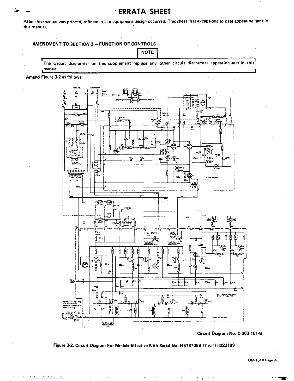
ERRATA
SHEET
After
this
manual
was
printed,
refinements
in
equipment
design
occurred.
This
sheet
lists
exceptions
to
data
appearing
later
in
this
manual.
AMENDMENT
TO
SECTION
3
FUNCTION
OF
CONTROLS
~NOTE~
The
circuit
1manual.
diagram(s)
on
this
supplement
replace
any
other
circuit
diagram(s)
appearing
later
in
this
i
Circuit
Diagram
No.
C-003
161-B
Amend
Figure
3-2
as
follows:
I..
~
~
I
___________________________________________________________________________
;flcff~
A
A
A
A.~.
r~r
I
at
~a~~
aoo
p
Figure
3-2.
Circuit
Diagram
For
Models
Effective
With
Serial
No.
HE787389
Thru
HH023189
A
c-tn
AA
C
C
r
POWIR
WORIC
----LW
r~,
~
a
I1
.a,()a.
f
i
___
_____
~
______
~E~i~_:~J
~I1~J
a
OM-1510
Page
A
OM-1510
Page
B
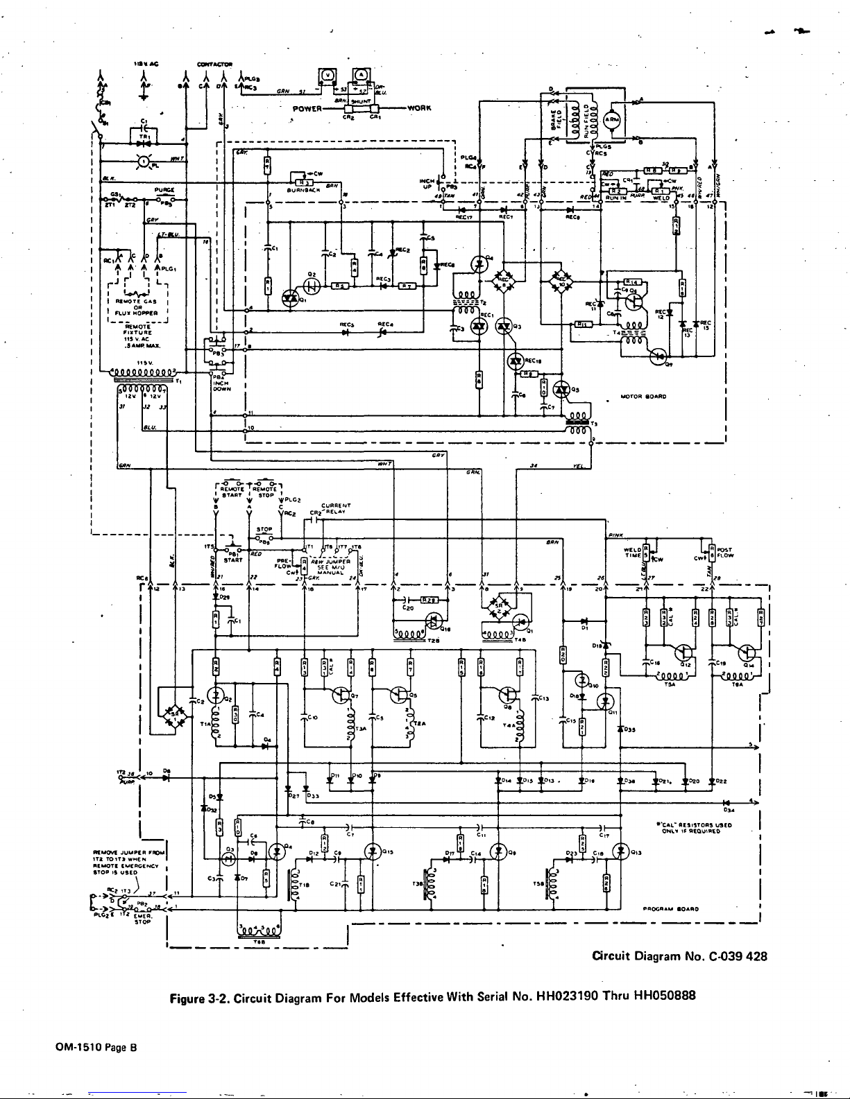
Figure
3-2.
Circuit
Diagram
For
Models
Effective
With
Serial
No.
HH023190
Thru
HH050888
HIS
AC
A
~,.
1~2
:~
~
I
~
AA
APLO,
IL,
II
I
I
R1000E
GXS
I
I
OX
I
FI.U0
ROPOPS
I
I
i
IRMOTE
I
FIXTURE
HR
V.
AC
.SA~W
MAO.
55-
I
~
I
____________
I
5000900O~
XV
3?
1J2
.7
A
A
AILGS
LI
z:::i:~~~
_______
PLR4
~
C
5C5
r-i
w
I
~0
P
£
0
C
I
Ii
11CR
_L
CR,
.~
~
~
~
Al
Al
X(I
~?~~~L?}S
T
~
~.
.
_i::~~i
z.~
SAC
1
-
jjl_
A
MOTOR
bARD
A
R
A
Ill
I3I~
121
LI
2.1
~
1~–j2
Dy
lAO
AS??
-~
REMOTE
REMOTE
I
START
I
STOP
-
V
14?
4lP~~2
I
V
C~~El~~T
_________
________________
~j
~
2~
~
::
,26–~L__
H
__
~
~lcfi
R~
TCj~~~i2A
T~
fIX
~
_________T~AJ
-
-
~
~DT
S
912
915
~O,3
~
~l1U,.
~99o
09;
I
~i
i~
C
-
~
iI;
~~ES
STOPS
UREA
~T3UW:~S~012I
-_.~E~
~Z1~
r
)C~~,__4
)o.~
DjjI
~
~
)~
;iv
IMERGETICT
.1
CS1
___
I~
C;,1
IF
U3R~
IF
PROGRAM
I
2
ERAS.
I
2.
033
Circuit
Diagram
No.
C-039
428
-
III-
115W
AC
A
A
B
JAA
L~
P0
WER
WORK
~WT
UP
P51802
JR
A
A A
~
I
I
r~i
IL1
I~5Wj
REMOTE
CR5
I
OR
FLUX
HOPPER
I
REMOTE
FIXTURE
115
5.
AC
.5AMP
MAX.
ISV.
5000
000,
25
25.
37
~Z
PAN
SUKNS~5
4,
BEll?
F
£
C~UC5
A
P
9(1
j
D.~1
~
W1TD
15111121
RFCR
R
II
~
~R,EzC*I
kn.os~J
T4C~
15
a,
_________
P1.04
RC4
~
42
I
1
_________________
–If:
~0E~
+4RE~~
__
sd?1
RECS
REC.
.~O3
0v1R~
i~~
H-
~
lOAN
I
a;
0
~
REMOTE
REMOTE
I
STARTISTOP
I
?~?PLG2
CURRETIT
~y
V(
RC2
CR2
RELAY
I
!
~
~i1I~
_______
______
________________
1
I.t~~se
j~.
.T5~)
~rT
,,~
BAN
.L1 j 1
..~
~60
o-
Ł
rs
o_,
~LOIRI..J
LJRI~5T
J
PR.
IP(O
I
._
-
TIMEISF
lRIFLOW
START
I
PRE.
SIN
JUMPER
I
L.~
W
CW
43
I I
FLOW
A
SEE
M,O
I.
A1
I
CW$
IANSUAL
I~
~
6
7
~I
H
~
~
A
~
57
2
-
3
5
I
~
~
-
22t
-
_L
_____
~
~ZR.
~~TAR
____
~
~~?ZA
C19
TIA~
~
-
-
TIP
~?I
>5
014
0.5
0fl3
HIS
D3R
402.
~O20
022
05
27
033
______________________________
14
~
032
034
-
I
RI
~
TCR
.~
_________________________
________________________
RCA1.
RESISTORS
US(D
3J
~
j
t
T
ONLH
IF
R(QUJIEO
,..
c.
~
C~
~~i
Cl?
I7
Cl?
REMOTE
lUMPER
FXOM~
__IL
~IE-1~
)22
DJ11
CX
)OIS
~
~
)
~
~
)~
REMOTE
EMERGEIACP
~
I
I
I
r~
j
rf
SlOP
IS
USED
~
(_3
rc~
_L
C)
07
~
H
R
I
11j
~r,R
1211
I
T3S~
155
PROGRAM
bARD
P5.522
72
~
I
_______
.
I___~-
?~
035
~1
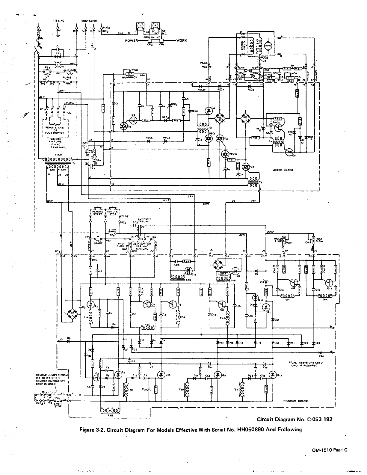
Figure
3-2.
Circuit
Diagram
For
Models
Effective
With
Serial
No.
HH050890
And
Following
circuit
Diagram
No.
C-053
192
OM-1510
Page
C
Item
or
Dia.
Part
No.
Listed
Replaced
With
ftem3l
079281
Item5O
073211
Item
53
~R
1
030
131
Jtem56
073722
Item57
073719
2
ftem72
073642
Item
C
602
071
14
Page
4
06
073
535
Page4
RB
605919
Page
4
R9
074026
Page4
R15
078429
CR4
Cl
073715
1
C2
.
039482
C3.15
073714
2
C4
073716
1
C5,12,21
073740
3
C6,9.14,18
073739
4
C7,8,11,17
073738
4
C10,13,19
073732
3
C16
073737
1
C20
073547
1
01,4-18,20-
23,27,29,
32.36
27
D19
1
01,4,9,11
13,15
6
02,3,10
3
05,7,8,
12,14
037289
5
016
073710
1
Al
078426
1
R2
605909
1
R3,20
605910
2
R4
030853
1
R5,21
605916
2
R6
078434
1
R7
,14,17,
24,27,29,
37
7
R
10,
12,
19,
25
605
908
4
R13,16,28
605911
3
R15
035830
1
R18,26
-
078428
2
R22
078431
1
R23
030091
1
R30
078433
1
R34,35,36
605919
3
R38
030016
1
SR1,2
074453
2
T1,2,4
073
682
3
T3,5,6
000
350
3
Item
4
075
318
-=
Page
No.
Mkgs.
-,
In
Parts
List
-
Part
No.
Description
Quantity
PB3
PB3,4
R
2,4,5,6.
1
2
1
1
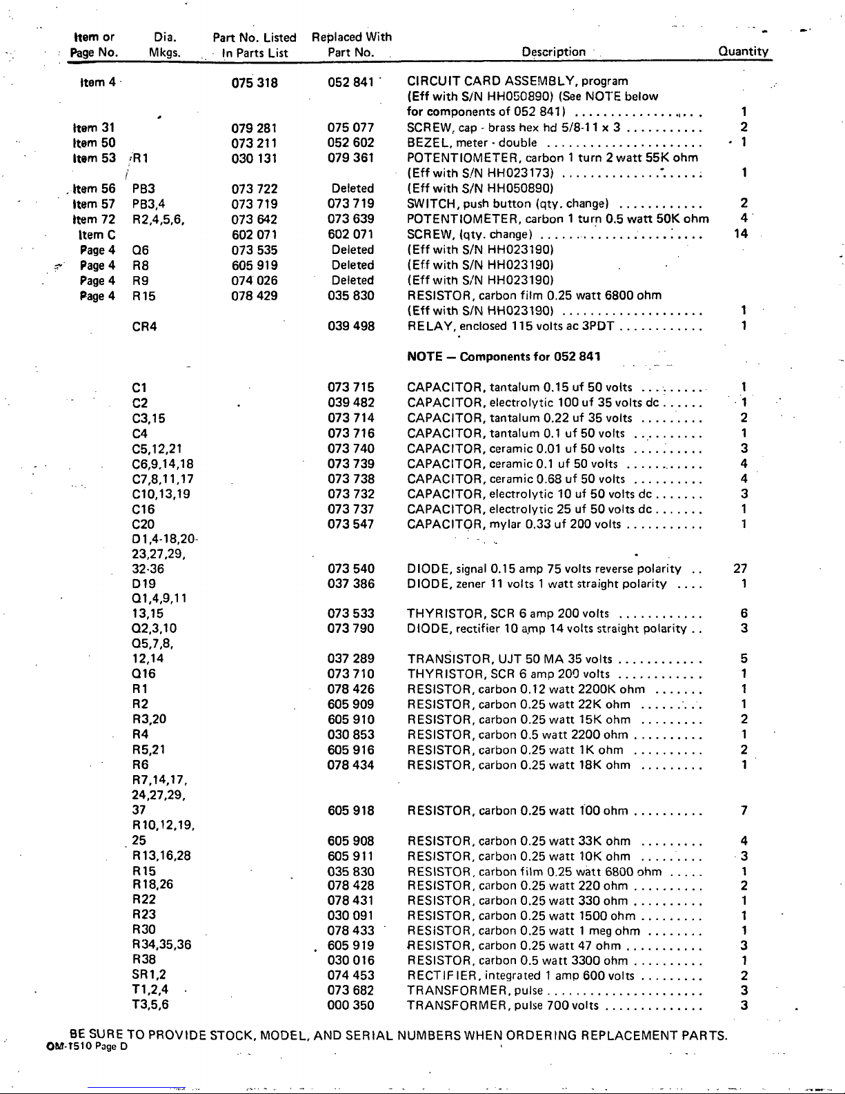
052
841
-
CIRCUIT
CARD
ASSEMBLY,
program
(Eff
with
S/N
HH050890)
(See
NOTE
below
for
components
of
052
841)
075
077
SCREW,
cap
-
brass
hex
hd
5/8-1
1
x
3
052
602
BEZEL,
meter
.
double
079
361
POTENTIOMETER,
carbon
1
turn
2
watt
55K
ohm
(Eff
with
S/N
HH023173)
Deleted
(Eff
with
S/N
HH050890)
073
719
SWITCH,
push
button
(qty.
change)
073 639
POTENTIOMETER,
carbon
1
turn
0.5
watt
50K
ohm
602
071
SCREW,
(qty.
change)
Deleted
(Eff
with
S/N
HH023190)
Deleted
(Elf
with
S/N
HH023190)
Deleted
(Eff
with
S,N
HH023190)
035
830
RESISTOR,
carbon
film
0.25
watt
6800
ohm
(Eff
with
S/N
HH023190)
039
498
RELAY,
enclosed
115
volts
ac
3PDT
1
1
NOTE
Components
for
052
841
CAPACITOR,
tantalum
0.15uf50
volts
CAPACITOR,
electrolytic
100
uf
35
volts
dc
CAPACITOR,
tantalum
0.22
uf
35
volts
CAPACITOR,
tantalum
0.1
uf
50
volts
CAPACITOR,
ceramic
0.01
uf
50
volts
CAPACITOR,
ceramic
0.1
uf
50
volts
CAPACITOR,
ceramic
0.68
uf
50
volts
CAPACITOR,
electrolytic
10uf50
volts
dc
CAPACITOR,
electrolytic
25uf50
volts
dc
CAPACITOR,
mylar
0.33
uf
200
volts
073
540
DIODE,
signal
0.15
amp
75
volts
reverse
polarity
037
386
DIODE,
zener
11
volts
1
watt
straight
polarity
.
073533
THYRISTOR,SCR
6amp200volts
073
790
DIODE,
rectifier
10
amp
14
volts
straight
polarity
-
TRANSISTOR,
UJT
50
MA
35
volts
THYRISTOR,
SCR
6
amp
200
volts
RESISTOR,
carbon
0.12
watt
2200K
ohm
RESISTOR,
carbon
0.25
watt
22K
ohm
RESISTOR,
carbon
0.25
watt
15K
ohm
RESISTOR,
carbon
0.5
watt
2200
ohm
RESISTOR,
carbon
0.25
watt
1K
ohm
RESISTOR,
carbon
0.25
watt
18K
ohm
605
918
RESISTOR,
carbon
0.25
watt
100
ohm
RESISTOR,
carbon
0.25
watt
33K
ohm
RESISTOR,
carbon
0.25
watt
10K
ohm
RESISTOR,
carbon
film
0.25
watt
6800
ohm
RESISTOR,
carbon
0.25
watt
220
ohm
RESISTOR,
carbon
0.25
watt
330
ohm
RESISTOR,
carbon
0.25
watt
1500
ohm
RESISTOR,
carbon
0.25
watt
1
meg
ohm
IRESISTOR,
carbon
0.25
watt
47
ohm
RESISTOR,
carbon
0.5
watt
3300
ohm
RECTIFIER,
integrated
1
amp
600
volts
TRANSFORMER,
pulse
TRANSFORMER,
pulse
700
volts
NUMBERS
WHEN
ORDERING
REPLACEMENT
PARTS.
BE
SURE
TO
PROVIDE
STOCK.
MODEL,
AND
SERIAL
OM-t5lOPzigeD
 Loading...