

Miller Electric MPi 220P Owner's Manual

OM-253 918B 2012−02
Processes
Description
MPi 220P
Multiprocess Welding
CE
Visit our website at
www.MillerWelds.com
File: Multiprocess

From Miller to You
Thank you and congratulations on choosing Miller. Now you can get the
job done and get it done right. We know you don’t have time to do it any
other way.
That’s why when Niels Miller first started building arc welders in 1929,
he made sure his products offered long-lasting value and superior quality.
Like you, his customers couldn’t afford anything less. Miller products had
to be more than the best they could be. They had to be the best you could
buy.
Today, the people that build and sell Miller products continue the
tradition. They’re just as committed to providing equipment and service
that meets the high standards of quality and value established in 1929.
This Owner’s Manual is designed to help you get the most out of your
Miller products. Please take time to read the Safety precautions. They will
help you protect yourself against potential hazards on the worksite. We’ve
made installation and operation quick and easy. With Miller you can
count on years of reliable service with proper maintenance. And if for
some reason the unit needs repair, there’s a Troubleshooting section that
will help you figure out what the problem is. The parts list will then help
you to decide which exact part you may need to fix the problem.
Warranty and service information for your particular model are also
provided.
Working as hard as you do
− every power source from
Miller is backed by the most
hassle-free warranty in the
business.
Miller Electric manufactures a full line of
welders and welding related equipment. For
information on other quality Miller products, contact your local Miller
distributor to receive the latest full line catalog or individual catalog sheets.

TABLE OF CONTENTS
SECTION 1 − SAFETY PRECAUTIONS - READ BEFORE USING 1.................................
1-1. Symbol Usage 1.......................................................................
1-2. Arc Welding Hazards 1.................................................................
1-3. Additional Symbols For Installation, Operation, And Maintenance 3.............................
1-4. California Proposition 65 Warnings 4......................................................
1-5. Principal Safety Standards 4.............................................................
1-6. EMF Information 4.....................................................................
SECTION 2 − DEFINITIONS 5..................................................................
2-1. WEEE Label 7.........................................................................
2-2. Symbols And Definitions 8...............................................................
SECTION 3 − SPECIFICATIONS 9..............................................................
3-1. Important Information Regarding CE Products (Sold Within The EU) 9..........................
3-2. Information On Electromagnetic Compatibility (EMC) 9.......................................
3-3. Specifications 9........................................................................
3-4. Duty Cycle And Overheating 10...........................................................
3-5. Volt-Ampere Curves 11..................................................................
SECTION 4 − INSTALLATION 12................................................................
4-1. Serial Number And Rating Label Location 12................................................
4-2. Selecting A Location 12..................................................................
4-3. Installing Gas Supply 13.................................................................
4-4. Weld Output Terminals And Selecting Cable Sizes* 14........................................
4-5. Process/Polarity Table 14................................................................
4-6. Changing Polarity 15....................................................................
4-7. Installing Wire Spool And Adjusting Hub Tension 16...........................................
4-8. Changing Drive Rolls And Wire Inlet Guide 17...............................................
4-9. Aligning Drive Rolls and Wire Guide 18.....................................................
4-10. Electrical Service Guide 19...............................................................
4-11. Connecting 230 VAC Single Phase Input Power 20...........................................
4-12. Threading Welding Wire And Adjusting Pressure Roll Tension 21...............................
SECTION 5 − OPERATION 22...................................................................
5-1. Controls 22............................................................................
5-2. Preparing Unit For Stick Welding 23........................................................
5-3. Preparing Unit For TIG Welding 24.........................................................
5-4. 2T − 4T Trigger Mode Selection (TIG Process) 25............................................
5-5. Preparing Unit For Manual MIG (GMAW And FCAW) Welding Process 26........................
5-6. Manual MIG Welding Set-Up Menu 27......................................................
5-7. Trigger Mode And Spot Time Selection (MIG Process) 29......................................
5-8. Preparing Unit For Synergic MIG (GMAW And FCAW) Welding Process 30.......................
5-9. Synergic MIG Welding Set-Up Menu 31.....................................................
5-10. Preparing Unit For Synergic Pulsed MIG (GMAW And FCAW) Welding Process 33................
5-11. Synergic Pulsed MIG Welding Set-Up Menu 35..............................................
5-12. 4T Trigger Set-Up Menu (Synergic Pulsed MIG Welding Only) 36...............................
5-13. Welding Wire Loading Settings 37.........................................................
5-14. Resetting Unit To Factory Default Settings 38................................................
5-15. Loading A Program 38...................................................................
5-16. Operator Point MIG Parameters Loading 39.................................................
5-17. Rated Supply Current I1 = 16 Amps Setting 40...............................................
5-18. Basic Set-Up Menu Parameters Settings 41.................................................

TABLE OF CONTENTS
SECTION 6 − MAINTENANCE & TROUBLESHOOTING 42.........................................
6-1. Routine Maintenance 42.................................................................
6-2. Welding Gun And Wire Drive Assembly 42..................................................
6-3. Unit Overload 42........................................................................
6-4. Troubleshooting 43......................................................................
SECTION 7 − ELECTRICAL DIAGRAMS 46.......................................................
SECTION 8 − MIG WELDING (GMAW) GUIDELINES 48............................................
8-1. Typical MIG Process Connections 48......................................................
8-2. Typical MIG Process Control Settings 49....................................................
8-3. Holding And Positioning Welding Gun 50....................................................
8-4. Conditions That Affect Weld Bead Shape 51.................................................
8-5. Gun Movement During Welding 52.........................................................
8-6. Poor Weld Bead Characteristics 52........................................................
8-7. Good Weld Bead Characteristics 52........................................................
8-8. Troubleshooting − Excessive Spatter 53....................................................
8-9. Troubleshooting − Porosity 53.............................................................
8-10. Troubleshooting − Excessive Penetration 53.................................................
8-11. Troubleshooting − Lack Of Penetration 54...................................................
8-12. Troubleshooting − Incomplete Fusion 54....................................................
8-13. Troubleshooting − Burn-Through 54........................................................
8-14. Troubleshooting − Waviness Of Bead 55....................................................
8-15. Troubleshooting − Distortion 55............................................................
8-16. Common MIG Shielding Gases 56.........................................................
8-17. Troubleshooting Guide For Semiautomatic Welding Equipment 56...............................
SECTION 9 − STICK WELDING (SMAW) GUIDELINES 58..........................................
SECTION 10 − SELECTING AND PREPARING A
TUNGSTEN
FOR DC OR AC WELDING WITH INVERTER MACHINES 65........................................
10-1. Selecting Tungsten Electrode (Wear Clean Gloves To Prevent Contamination Of Tungsten) 65......
10-2. Preparing Tungsten Electrode For DC Electrode Negative (DCEN) Welding
Or AC Welding With Inverter Machines 65...................................................
SECTION 11 − GUIDELINES FOR TIG WELDING (GTAW) 66........................................
11-1. Positioning The Torch 66.................................................................
11-2. Torch Movement During Welding 67........................................................
11-3. Positioning Torch Tungsten For Various Weld Joints 67........................................
SECTION 12 − PARTS LIST 68..................................................................
WARRANTY

DECLARATION OF CONFORMITY
for European Community (CE marked) products.
ITW Welding Products Italy S.r.l Via Privata Iseo 6/E, 20098 San Giuliano M.se, (MI) Italy declares that
the product(s) identified in this declaration conform to the essential requirements and provisions of
the stated Council Directive(s) and Standard(s).
Product/Apparatus Identification:
Product Stock Number
MPi 220P 230VAC 059016014
Council Directives:
2006/95/EC Low Voltage
2004/108/EC Electromagnetic Compatibility
Standards:
IEC 609741 Arc Welding Equipment Welding Power Sources: edition 3, 200507.
IEC 609745 Arc Welding Equipment – Wire Feeders: edition 2, 200711.
IEC 6097410 Arc Welding Equipment Electromagnetic Compatibility Requirements: edition 2.0, 200708.
EN 50445:2008 Product family standard to demonstrate compliance of equipment for resistance welding, arc
welding and allied processes with the basic restrictions related to human exposure to electromagnetic fields
(0Hz300Hz)
EU Signatory:
September 30th, 2011
___________________________________________________________________________________
Massimigliano Lavarini Date of Declaration
ELECTRONIC ENGINEER R&D TECH. SUPPORT
956 142 896

SECTION 1 − SAFETY PRECAUTIONS - READ BEFORE USING
7
Protect yourself and others from injury — read, follow, and save these important safety precautions and operating instructions.
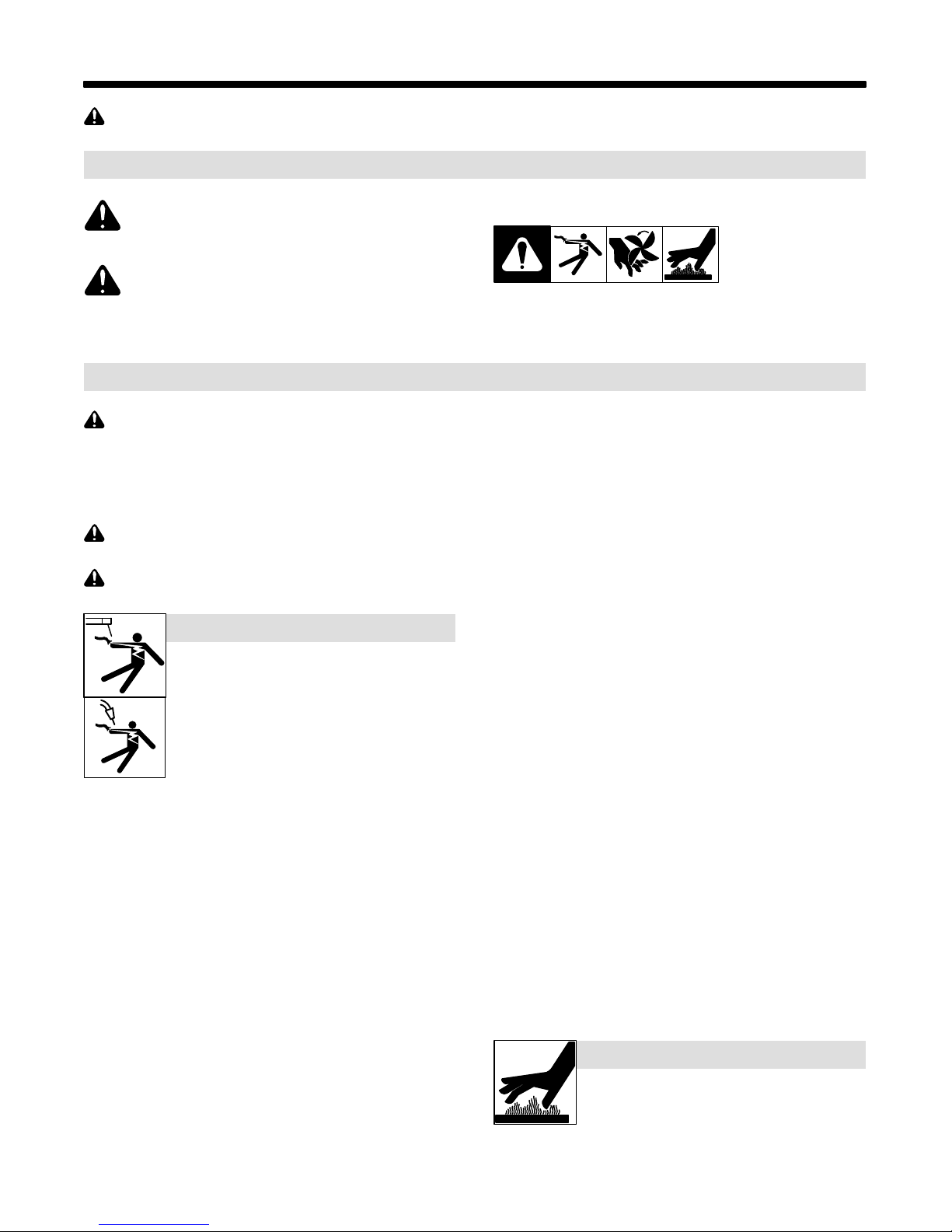
1-1. Symbol Usage
som 2011−10
DANGER! − Indicates a hazardous situation which, if
not avoided, will result in death or serious injury. The
possible hazards are shown in the adjoining symbols
or explained in the text.
Indicates a hazardous situation which, if not avoided,
could result in death or serious injury. The possible
hazards are shown in the adjoining symbols or explained in the text.
NOTICE − Indicates statements not related to personal injury.
1-2. Arc Welding Hazards
The symbols shown below are used throughout this manual
to call attention to and identify possible hazards. When you
see the symbol, watch out, and follow the related instructions
to avoid the hazard. The safety information given below is
only a summary of the more complete safety information
found in the Safety Standards listed in Section 1-5. Read and
follow all Safety Standards.
Only qualified persons should install, operate, maintain, and
repair this unit.
During operation, keep everybody, especially children, away.
ELECTRIC SHOCK can kill.
Touching live electrical parts can cause fatal shocks
or severe burns. The electrode and work circuit is
electrically live whenever the output is on. The input
power circuit and machine internal circuits are also
live when power is on. In semiautomatic or automatic
wire welding, the wire, wire reel, drive roll housing,
and all metal parts touching the welding wire are
electrically live. Incorrectly installed or improperly
grounded equipment is a hazard.
D Do not touch live electrical parts.
D Wear dry, hole-free insulating gloves and body protection.
D Insulate yourself from work and ground using dry insulating mats
or covers big enough to prevent any physical contact with the work
or ground.
D Do not use AC output in damp areas, if movement is confined, or if
there is a danger of falling.
D Use AC output ONLY if required for the welding process.
D If AC output is required, use remote output control if present on
unit.
D Additional safety precautions are required when any of the follow-
ing electrically hazardous conditions are present: in damp
locations or while wearing wet clothing; on metal structures such
as floors, gratings, or scaffolds; when in cramped positions such
as sitting, kneeling, or lying; or when there is a high risk of unavoidable or accidental contact with the workpiece or ground. For these
conditions, use the following equipment in order presented: 1) a
semiautomatic DC constant voltage (wire) welder, 2) a DC manual
(stick) welder, or 3) an AC welder with reduced open-circuit voltage. In most situations, use of a DC, constant voltage wire welder
is recommended. And, do not work alone!
D Disconnect input power or stop engine before installing or
servicing this equipment. Lockout/tagout input power according to
OSHA 29 CFR 1910.147 (see Safety Standards).
D Properly install, ground, and operate this equipment according to
its Owner’s Manual and national, state, and local codes.
. Indicates special instructions.
This group of symbols means Warning! Watch Out! ELECTRIC
SHOCK, MOVING PARTS, and HOT PARTS hazards. Consult symbols and related instructions below for necessary actions to avoid the
hazards.
D Always verify the supply ground − check and be sure that input
power cord ground wire is properly connected to ground terminal in
disconnect box or that cord plug is connected to a properly
grounded receptacle outlet.
D When making input connections, attach proper grounding conduc-
tor first − double-check connections.
D Keep cords dry, free of oil and grease, and protected from hot metal
and sparks.
D Frequently inspect input power cord for damage or bare wiring −
replace cord immediately if damaged − bare wiring can kill.
D Turn off all equipment when not in use.
D Do not use worn, damaged, undersized, or poorly spliced cables.
D Do not drape cables over your body.
D If earth grounding of the workpiece is required, ground it directly
with a separate cable.
D Do not touch electrode if you are in contact with the work, ground,
or another electrode from a different machine.
D Do not touch electrode holders connected to two welding ma-
chines at the same time since double open-circuit voltage will be
present.
D Use only well-maintained equipment. Repair or replace damaged
parts at once. Maintain unit according to manual.
D Wear a safety harness if working above floor level.
D Keep all panels and covers securely in place.
D Clamp work cable with good metal-to-metal contact to workpiece
or worktable as near the weld as practical.
D Insulate work clamp when not connected to workpiece to prevent
contact with any metal object.
D Do not connect more than one electrode or work cable to any
single weld output terminal. Disconnect cable for process not in
use.
SIGNIFICANT DC VOLTAGE exists in inverter welding power sources AFTER removal of input power.
D Turn Off inverter, disconnect input power, and discharge input
capacitors according to instructions in Maintenance Section
before touching any parts.
HOT PARTS can burn.
D Do not touch hot parts bare handed.
D Allow cooling period before working on equip-
ment.
D To handle hot parts, use proper tools and/or
wear heavy, insulated welding gloves and
clothing to prevent burns.
OM-253 918 Page 1
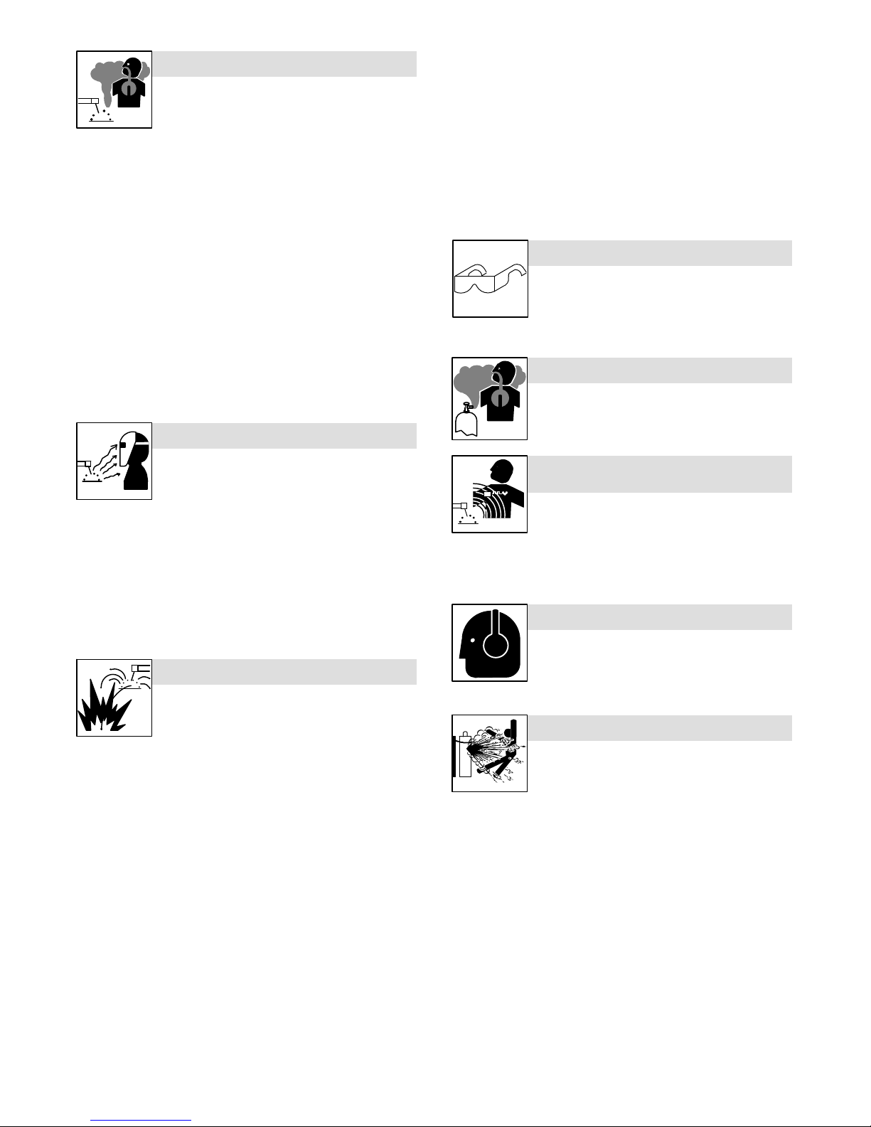
FUMES AND GASES can be hazardous.
)
Welding produces fumes and gases. Breathing
these fumes and gases can be hazardous to your
health.
D Keep your head out of the fumes. Do not breathe the fumes.
D If inside, ventilate the area and/or use local forced ventilation at the
arc to remove welding fumes and gases.
D If ventilation is poor, wear an approved air-supplied respirator.
D Read and understand the Material Safety Data Sheets (MSDSs)
and the manufacturer’s instructions for metals, consumables,
coatings, cleaners, and degreasers.
D Work in a confined space only if it is well ventilated, or while
wearing an air-supplied respirator. Always have a trained watchperson nearby. Welding fumes and gases can displace air and
lower the oxygen level causing injury or death. Be sure the breathing air is safe.
D Do not weld in locations near degreasing, cleaning, or spraying op-
erations. The heat and rays of the arc can react with vapors to form
highly toxic and irritating gases.
D Do not weld on coated metals, such as galvanized, lead, or
cadmium plated steel, unless the coating is removed from the weld
area, the area is well ventilated, and while wearing an air-supplied
respirator. The coatings and any metals containing these elements
can give off toxic fumes if welded.
ARC RAYS can burn eyes and skin.
D Remove stick electrode from holder or cut off welding wire at
contact tip when not in use.
D Wear oil-free protective garments such as leather gloves, heavy
shirt, cuffless trousers, high shoes, and a cap.
D Remove any combustibles, such as a butane lighter or matches,
from your person before doing any welding.
D After completion of work, inspect area to ensure it is free of sparks,
glowing embers, and flames.
D Use only correct fuses or circuit breakers. Do not oversize or by-
pass them.
D Follow requirements in OSHA 1910.252 (a) (2) (iv) and NFPA 51B
for hot work and have a fire watcher and extinguisher nearby.
FLYING METAL or DIRT can injure eyes.
D Welding, chipping, wire brushing, and grinding
cause sparks and flying metal. As welds cool,
they can throw off slag.
D Wear approved safety glasses with side
shields even under your welding helmet.
BUILDUP OF GAS can injure or kill.
D Shut off compressed gas supply when not in use.
D Always ventilate confined spaces or use
approved air-supplied respirator.
Arc rays from the welding process produce intense
visible and invisible (ultraviolet and infrared) rays
that can burn eyes and skin. Sparks fly off from the
weld.
D Wear an approved welding helmet fitted with a proper shade of
filter lenses to protect your face and eyes from arc rays and
sparks when welding or watching (see ANSI Z49.1 and Z87.1
listed in Safety Standards).
D Wear approved safety glasses with side shields under your
helmet.
D Use protective screens or barriers to protect others from flash,
glare and sparks; warn others not to watch the arc.
D Wear protective clothing made from durable, flame-resistant
material (leather, heavy cotton, or wool) and foot protection.
WELDING can cause fire or explosion.
Welding on closed containers, such as tanks,
drums, or pipes, can cause them to blow up. Sparks
can fly off from the welding arc. The flying sparks, hot
burns. Accidental contact of electrode to metal objects can cause
sparks, explosion, overheating, or fire. Check and be sure the area is
safe before doing any welding.
D Remove all flammables within 35 ft (10.7 m) of the welding arc. If
this is not possible, tightly cover them with approved covers.
D Do not weld where flying sparks can strike flammable material.
D Protect yourself and others from flying sparks and hot metal.
D Be alert that welding sparks and hot materials from welding can
easily go through small cracks and openings to adjacent areas.
D Watch for fire, and keep a fire extinguisher nearby.
D Be aware that welding on a ceiling, floor, bulkhead, or partition can
cause fire on the hidden side.
D Do not weld on containers that have held combustibles, or on
closed containers such as tanks, drums, or pipes unless they are
properly prepared according to AWS F4.1 and AWS A6.0 (see
Safety Standards).
D Do not weld where the atmosphere may contain flammable dust,
gas, or liquid vapors (such as gasoline).
D Connect work cable to the work as close to the welding area as
practical to prevent welding current from traveling long, possibly
unknown paths and causing electric shock, sparks, and fire
hazards.
D Do not use welder to thaw frozen pipes.
OM-253 918 Page 2
workpiece, and hot equipment can cause fires and
ELECTRIC AND MAGNETIC FIELDS (EMF
can affect Implanted Medical Devices.
D Wearers of Pacemakers and other Implanted
Medical Devices should keep away.
D Implanted Medical Device wearers should consult their doctor
and the device manufacturer before going near arc welding, spot
welding, gouging, plasma arc cutting, or induction heating
operations.
NOISE can damage hearing.
Noise from some processes or equipment can
damage hearing.
D Wear approved ear protection if noise level is
high.
CYLINDERS can explode if damaged.
Compressed gas cylinders contain gas under high
pressure. If damaged, a cylinder can explode. Since
gas cylinders are normally part of the welding
process, be sure to treat them carefully.
D Protect compressed gas cylinders from excessive heat, mechani-
cal shocks, physical damage, slag, open flames, sparks, and arcs.
D Install cylinders in an upright position by securing to a stationary
support or cylinder rack to prevent falling or tipping.
D Keep cylinders away from any welding or other electrical circuits.
D Never drape a welding torch over a gas cylinder.
D Never allow a welding electrode to touch any cylinder.
D Never weld on a pressurized cylinder − explosion will result.
D Use only correct compressed gas cylinders, regulators, hoses,
and fittings designed for the specific application; maintain them
and associated parts in good condition.
D Turn face away from valve outlet when opening cylinder valve.
D Keep protective cap in place over valve except when cylinder is in
use or connected for use.
D Use the right equipment, correct procedures, and sufficient num-
ber of persons to lift and move cylinders.
D Read and follow instructions on compressed gas cylinders,
associated equipment, and Compressed Gas Association (CGA)
publication P-1 listed in Safety Standards.
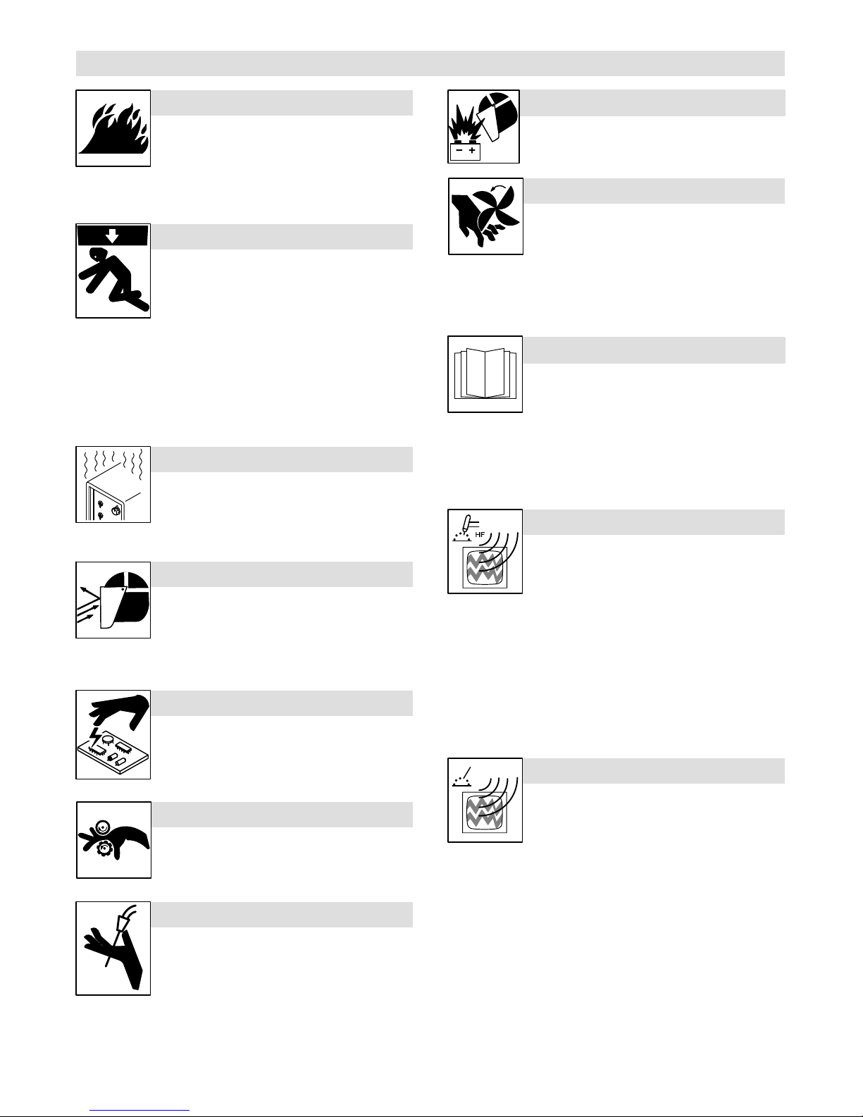
1-3. Additional Symbols For Installation, Operation, And Maintenance
FIRE OR EXPLOSION hazard.
D Do not install or place unit on, over, or near
combustible surfaces.
D Do not install unit near flammables.
D Do not overload building wiring − be sure power supply system is
properly sized, rated, and protected to handle this unit.
FALLING EQUIPMENT can injure.
D Use lifting eye to lift unit only, NOT running
gear, gas cylinders, or any other accessories.
D Use equipment of adequate capacity to lift and
support unit.
D If using lift forks to move unit, be sure forks are long enough to
extend beyond opposite side of unit.
D Keep equipment (cables and cords) away from moving vehicles
when working from an aerial location.
D Follow the guidelines in the Applications Manual for the Revised
NIOSH Lifting Equation (Publication No. 94−110) when manually lifting heavy parts or equipment.
OVERUSE can cause OVERHEATING
D Allow cooling period; follow rated duty cycle.
D Reduce current or reduce duty cycle before
starting to weld again.
D Do not block or filter airflow to unit.
FLYING SPARKS can injure.
D Wear a face shield to protect eyes and face.
D Shape tungsten electrode only on grinder with
proper guards in a safe location wearing proper
face, hand, and body protection.
D Sparks can cause fires — keep flammables away.
STATIC (ESD) can damage PC boards.
D Put on grounded wrist strap BEFORE handling
boards or parts.
D Use proper static-proof bags and boxes to
store, move, or ship PC boards.
BATTERY EXPLOSION can injure.
D Do not use welder to charge batteries or jump
start vehicles unless it has a battery charging
feature designed for this purpose.
MOVING PARTS can injure.
D Keep away from moving parts such as fans.
D Keep all doors, panels, covers, and guards
closed and securely in place.
D Have only qualified persons remove doors, panels, covers, or
guards for maintenance and troubleshooting as necessary.
D Reinstall doors, panels, covers, or guards when maintenance is
finished and before reconnecting input power.
READ INSTRUCTIONS.
D Read and follow all labels and the Owner’s
Manual carefully before installing, operating, or
servicing unit. Read the safety information at
the beginning of the manual and in each
section.
D Use only genuine replacement parts from the manufacturer.
D Perform maintenance and service according to the Owner’s
Manuals, industry standards, and national, state, and local
codes.
H.F. RADIATION can cause interference.
D High-frequency (H.F.) can interfere with radio
navigation, safety services, computers, and
communications equipment.
D Have only qualified persons familiar with
electronic equipment perform this installation.
D The user is responsible for having a qualified electrician prompt-
ly correct any interference problem resulting from the installation.
D If notified by the FCC about interference, stop using the
equipment at once.
D Have the installation regularly checked and maintained.
D Keep high-frequency source doors and panels tightly shut, keep
spark gaps at correct setting, and use grounding and shielding to
minimize the possibility of interference.
ARC WELDING can cause interference.
MOVING PARTS can injure.
D Keep away from moving parts.
D Keep away from pinch points such as drive
rolls.
WELDING WIRE can injure.
D Do not press gun trigger until instructed to do
so.
D Do not point gun toward any part of the body,
other people, or any metal when threading
welding wire.
D Electromagnetic energy can interfere with
sensitive electronic equipment such as
computers and computer-driven equipment
such as robots.
D Be sure all equipment in the welding area is
electromagnetically compatible.
D To reduce possible interference, keep weld cables as short as
possible, close together, and down low, such as on the floor.
D Locate welding operation 100 meters from any sensitive elec-
tronic equipment.
D Be sure this welding machine is installed and grounded
according to this manual.
D If interference still occurs, the user must take extra measures
such as moving the welding machine, using shielded cables,
using line filters, or shielding the work area.
OM-253 918 Page 3

1-4. California Proposition 65 Warnings
Welding or cutting equipment produces fumes or gases
which contain chemicals known to the State of California to
cause birth defects and, in some cases, cancer. (California
Health & Safety Code Section 25249.5 et seq.)
1-5. Principal Safety Standards
Safety in Welding, Cutting, and Allied Processes, ANSI Standard Z49.1,
is available as a free download from the American Welding Society at
http://www.aws.org or purchased from Global Engineering Documents
(phone: 1-877-413-5184, website: www.global.ihs.com).
Safe Practices for the Preparation of Containers and Piping for Welding
and Cutting, American Welding Society Standard AWS F4.1, from Glob-
al Engineering Documents (phone: 1-877-413-5184, website:
www.global.ihs.com).
Safe Practices for Welding and Cutting Containers that have Held Combustibles, American Welding Society Standard AWS A6.0, from Global
Engineering Documents (phone: 1-877-413-5184,
website: www.global.ihs.com).
National Electrical Code, NFPA Standard 70, from National Fire Protection Association, Quincy, MA 02269 (phone: 1-800-344-3555, website:
www.nfpa.org and www. sparky.org).
Safe Handling of Compressed Gases in Cylinders, CGA Pamphlet P-1,
from Compressed Gas Association, 14501 George Carter Way, Suite
103, Chantilly, VA 20151 (phone: 703-788-2700, website:www.cganet.com).
Safety in Welding, Cutting, and Allied Processes, CSA Standard
W117.2, from Canadian Standards Association, Standards Sales, 5060
1-6. EMF Information
This product contains chemicals, including lead, known to
the state of California to cause cancer, birth defects, or other
reproductive harm. Wash hands after use.
Spectrum Way, Suite 100, Ontario, Canada L4W 5NS (phone:
800-463-6727, website: www.csa-international.org).
Safe Practice For Occupational And Educational Eye And Face Protection, ANSI Standard Z87.1, from American National Standards Institute,
25 West 43rd Street, New York, NY 10036 (phone: 212-642-4900, website: www.ansi.org).
Standard for Fire Prevention During Welding, Cutting, and Other Hot
Work, NFPA Standard 51B, from National Fire Protection Association,
Quincy, MA 02269 (phone: 1-800-344-3555, website: www.nfpa.org.
OSHA, Occupational Safety and Health Standards for General Indus-
try, Title 29, Code of Federal Regulations (CFR), Part 1910, Subpart Q,
and Part 1926, Subpart J, from U.S. Government Printing Office, Superintendent of Documents, P.O. Box 371954, Pittsburgh, PA 15250-7954
(phone: 1-866-512-1800) (there are 10 OSHA Regional Offices—
phone for Region 5, Chicago, is 312-353-2220, website:
www.osha.gov).
Applications Manual for the Revised NIOSH Lifting Equation, The National Institute for Occupational Safety and Health (NIOSH), 1600
Clifton Rd, Atlanta, GA 30333 (phone: 1-800-232-4636, website:
www.cdc.gov/NIOSH).
Electric current flowing through any conductor causes localized electric
and magnetic fields (EMF). Welding current creates an EMF field
around the welding circuit and welding equipment. EMF fields may interfere with some medical implants, e.g. pacemakers. Protective
measures for persons wearing medical implants have to be taken. For
example, restrict access for passers−by or conduct individual risk assessment for welders. All welders should use the following procedures
in order to minimize exposure to EMF fields from the welding circuit:
1. Keep cables close together by twisting or taping them, or using a
cable cover.
2. Do not place your body between welding cables. Arrange cables
to one side and away from the operator.
3. Do not coil or drape cables around your body.
4. Keep head and trunk as far away from the equipment in the
welding circuit as possible.
5. Connect work clamp to workpiece as close to the weld as
possible.
6. Do not work next to, sit or lean on the welding power source.
7. Do not weld whilst carrying the welding power source or wire
feeder.
About Implanted Medical Devices:
Implanted Medical Device wearers should consult their doctor and the
device manufacturer before performing or going near arc welding, spot
welding, gouging, plasma arc cutting, or induction heating operations.
If cleared by your doctor, then following the above procedures is recommended.
OM-253 918 Page 4

SECTION 2 − DEFINITIONS
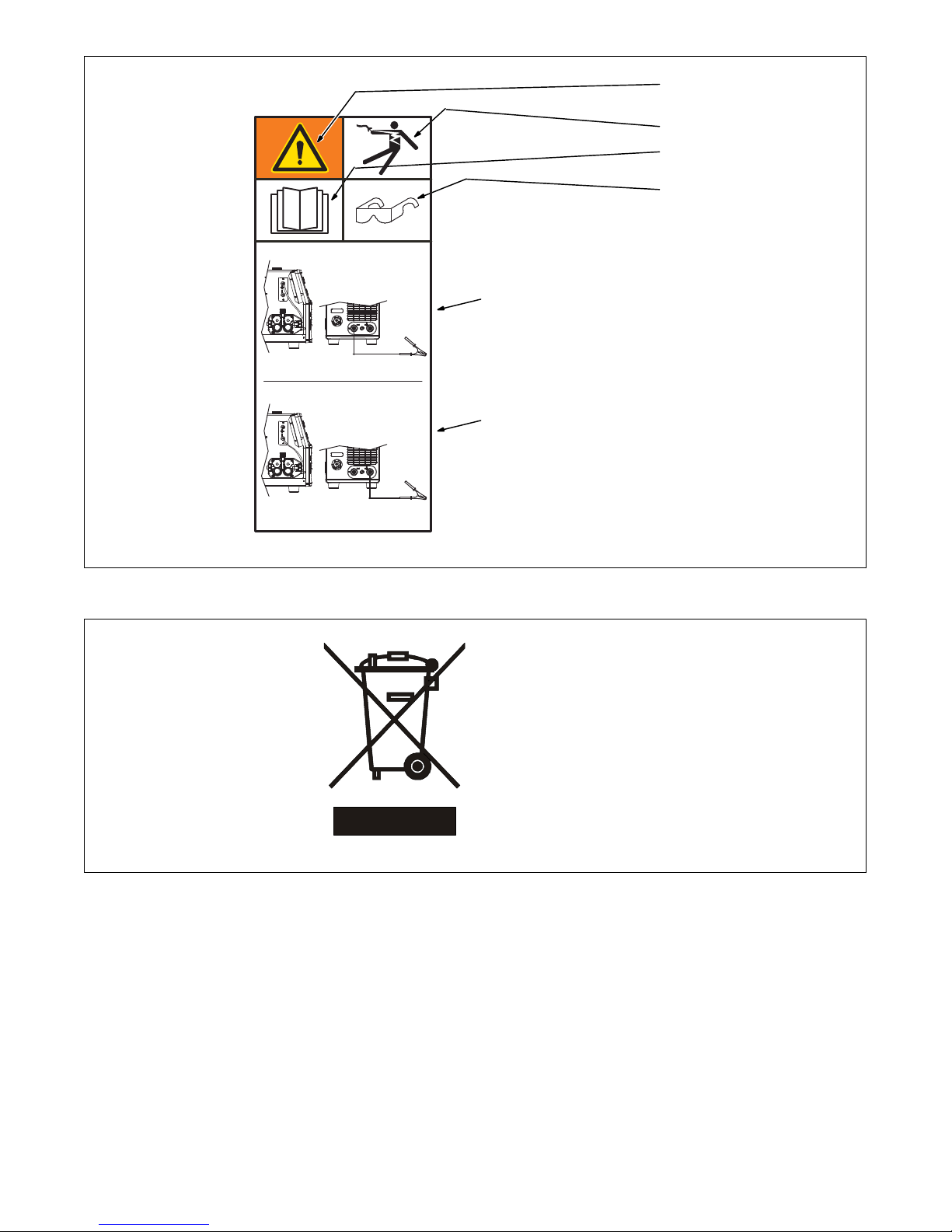
Warning! Watch Out! There are possible
hazards as shown by the symbols.
1 Electric shock can kill.
1.1 Wear dry insulating gloves. Do not
touch electrode with bare hand. Do
not wear wet or damaged gloves.
1.2 Protect yourself from electric shock
by insulating yourself from work and
ground.
1.3 Disconnect input plug or power
before working on machine.
2 Breathing welding fumes can be
hazardous to your health.
2.1 Keep your head out of the fumes.
2.2 Use forced ventilation or local
exhaust to remove the fumes.
2.3 Use ventilating fan to remove fumes.
3 Welding sparks can cause explosion
or fire.
3.1 Keep flammables away from welding.
Do not weld near flammables.
3.2 Welding sparks can cause fires.
Have a fire extinguisher nearby, and
have a watchperson ready to use it.
3.3 Do not weld on drums or any closed
containers.
4 Arc rays can burn eyes and injure
skin.
4.1 Wear hat and safety glasses. Use
ear protection and button shirt collar.
Use welding helmet with correct
shade of filter. Wear complete body
protection.
5 Become trained and read the
instructions before working on the
machine or welding.
6 Do not remove or paint over (cover)
the label.
Kasjf;laksf;lkasdf'l;aksdf;lkasd;flksadflkasd;lk
Kasjf;laksf;lkasdf'l;aksdf;lkasd;flksadflkasd;lk
Kasjf;laksf;lkasdf'l;aksdf;lkasd;flksadflkasd;lk
179310-B
1
1 Warning! Watch Out! There
are possible hazards as
shown by the symbols.
2 Drive rolls can injure fingers
3 Welding wire and drive parts
are at welding voltage during
operation − keep hands and
metal objects away.
2 3
OM-253 918 Page 5
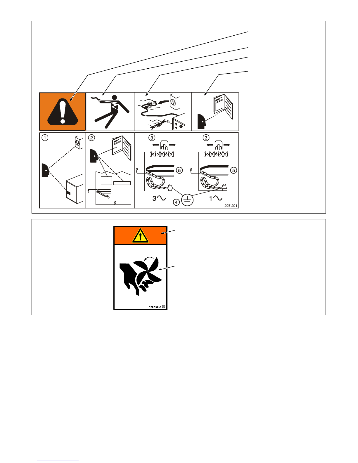
Warning! Watch Out! There are
possible hazards as shown by the
symbols.
Electric shock from wiring can kill.
Disconnect input plug or power
before working on machine.
Read the Owner’s Manual before
working on this machine.
1 Consult rating label for input
power requirements, and
check power available at the
job site − they must match.
2 Read Owner’s Manual and
inside labels for connection
points and procedures.
3 Move jumper links as shown
on inside label to match
voltage at job site.
4 Having a loop of extra length,
connect grounding conductor
first.
5 Connect line input conductors
as shown on inside label −
double-check all connections,
jumper link positions, and
input voltage before applying
power.
1
2
1 Warning! Watch Out! There
are possible hazards as
shown by the symbols.
2 Moving parts, such as fans,
can cut fingers and hands and
cause injury. Keep away from
moving parts.
OM-253 918 Page 6
DCEP
Electrode Positive
Warning! Watch Out! There are
possible hazards as shown by the
symbols.
Electric shock from wiring can kill.
Read the Owner’s Manual before
working on this machine.
Wear approved safety glasses.
1 Electrode Positive (Straight
Polarity)
2 Electrode Negative (Reverse
Polarity)
1
2-1. WEEE Label
DCEN
Electrode Negative
956.142.877−A
2
Do not discard this product with
general waste.
Reuse or recycle Waste Electrical
and Electronic Equipment (WEEE)
by disposing at a designated collection facility.
Contact your local recycling office
or your local distributor for further
information.
OM-253 918 Page 7
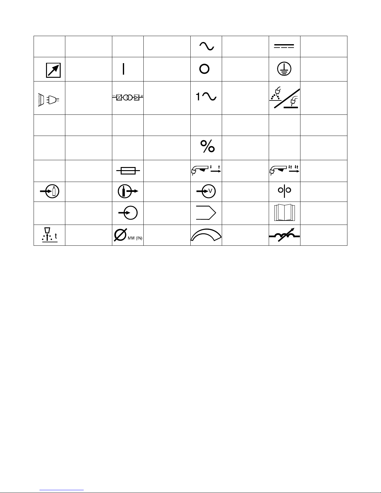
2-2. Symbols And Definitions
A
U
1
I
2
IP
Hz
Amperes
Remote On Off
Line Connection
Primary Voltage
Rated Welding
Current
Degree Of
Protection
Gas Input Gas Output Voltage Input Wire Feed
Hertz Input Program
V
I1max
X
Volts
Single Phase
Static Frequency
Converter-
Transformer-
Rectifier
Rated Maximum
Supply Current I1eff
Duty Cycle Percent
Fuse
Alternating Current
(AC)
Single Phase
Maximum Effective
Supply Current
Two-Step Trigger
Operation
U
U
0
Direct Current
Protective Earth
Gas Metal Arc
Welding (GMAW)
Conventional Load
2
Rated No Load
Voltage (Average)
Four-Step Trigger
Operation
Read Operator’s
(Ground)
Voltage
Manual
(DC)
Wire Burnback
Control
Diameter Increase/Decrease
Variable
Inductance
OM-253 918 Page 8
SECTION 3 − SPECIFICATIONS
3-1. Important Information Regarding CE Products (Sold Within The EU)
! This equipment shall not be used by the general public as the EMF limits for the general public might be exceeded during welding.
This equipment is built in accordance with EN 60974−1 and is intended to be used only in an occupational environment (where the general public
access is prohibited or regulated in such a way as to be similar to occupational use) by an expert or an instructed person.
Wire feeders and ancillary equipment (such as torches, liquid cooling systems and arc striking and stabilizing devices) as part of the welding
circuit may not be a major contributor to the EMF. See the Owner’s Manuals for all components of the welding circuit for additional EMF exposure
information.
S The EMF assessment on this equipment was conducted at 0.5 meter.
S At a distance of 1 meter the EMF exposure values were less than 20% of the permissible values.
3-2. Information On Electromagnetic Compatibility (EMC)
! This Class A equipment is not intended for use in residential locations where the electrical power is provided by the public low
voltage supply system. There may be potential difficulties in ensuring electromagnetic compatibility in those locations, due to
conducted as well as radiated disturbances.
! This equipment does not comply with IEC 61000−3−12. If it is connected to a public low voltage system, it is the responsibility of
the installer or user of the equipment to ensure, by consultation with the distribution network operator if necessary, that the equipment may be connected. ce-emc 2 2010-10
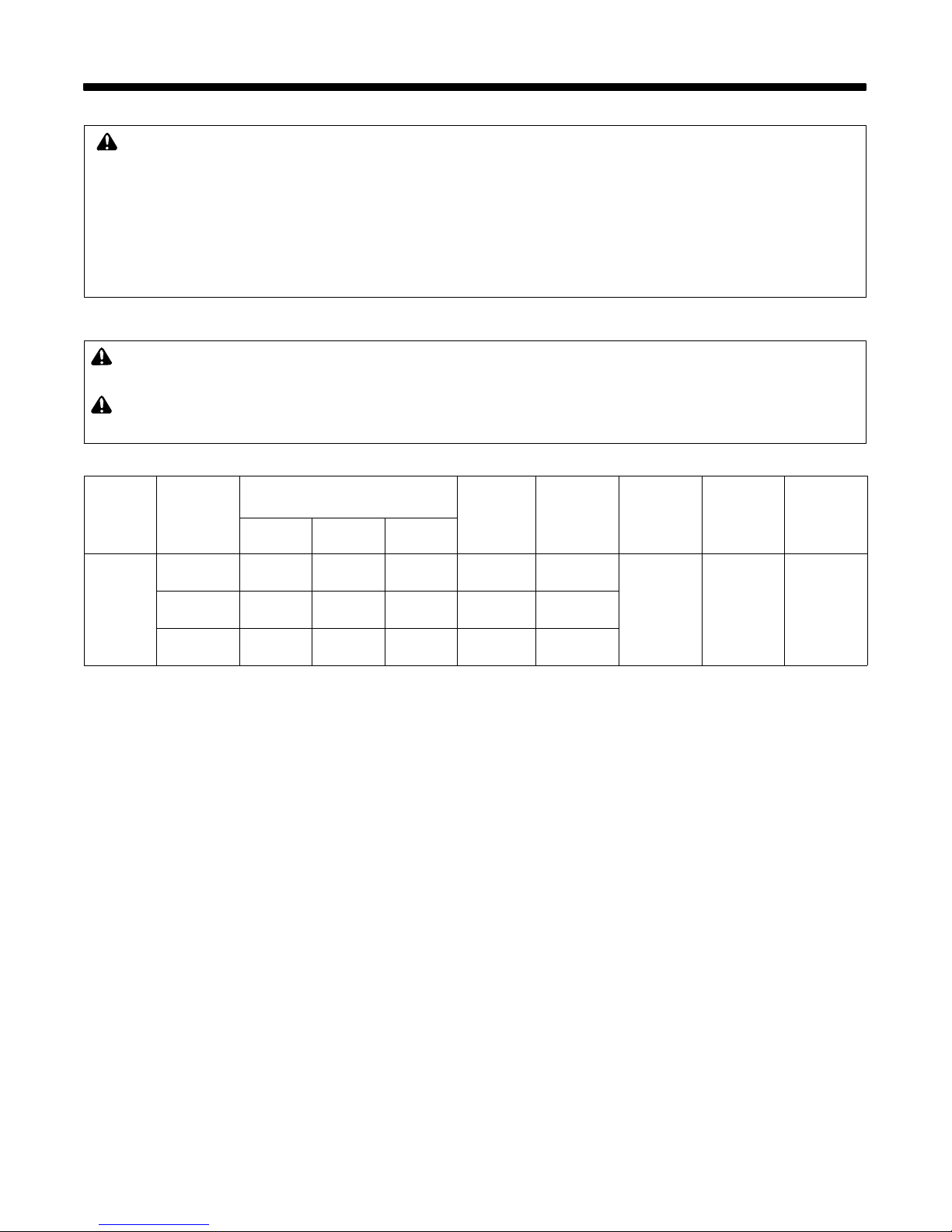
3-3. Specifications
Model
MPi 220P
Input Power
Single
Phase AC
50/60 Hz
Voltage
230 Volts
MIG
230 Volts
TIG
230 Volts
STICK
Rated Output
100% 60% 35%
110 A
17.5 V
100 A
14.0 V
100 A
24.0 V
140 A
21.0 V
130 A
15.2 V
130 A
25.2 V
180 A
23.0 V
180 A
17.2 V
170 A
26.8 V
Max. Open
Circuit
Voltage
35 V
65 V
65 V
Amperage/
Voltage
Range
DC
20 - 200 A
15.0 - 24.0 V
5 - 200 A
10.0 - 18.0 V
5 - 200 A
20.2 - 28.0 V
IP Rating Dimension
IP22S
(mm)
L = 548
W = 237
H = 365
Weight (kg)
16
OM-253 918 Page 9
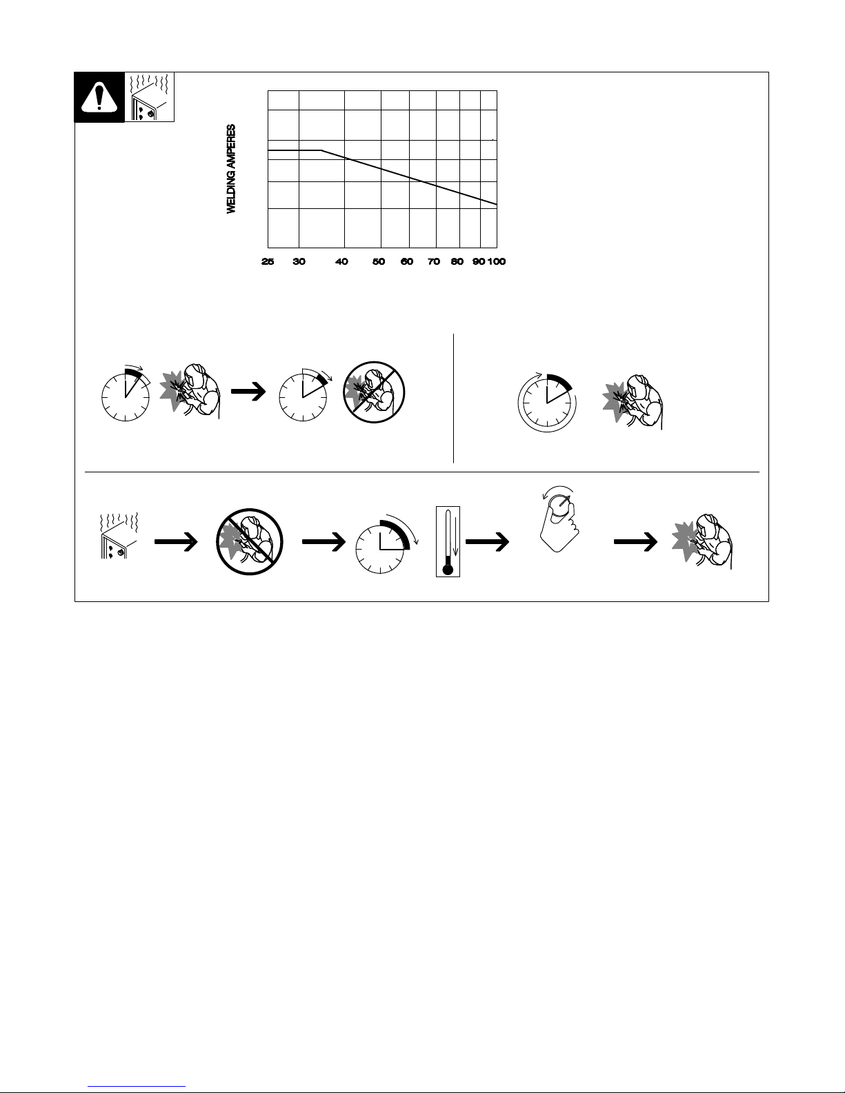
3-4. Duty Cycle And Overheating
250
200
175
150
100
50
Duty Cycle is percentage of 10
minutes that unit can weld at rated
load without overheating.
If unit overheats, thermostat(s)
opens, output stops, and cooling
fan runs. Wait fifteen minutes for
unit to cool. Reduce amperage or
duty cycle before welding.
NOTICE − Exceeding duty cycle
can damage unit or gun and void
warranty.
% DUTY CYCLE
60% Duty Cycle At 140 Amperes
6 Minutes Welding 4 Minutes Resting
Overheating
0
Minutes
15
100% Duty Cycle At 110 Amperes
Continuous Welding
A or V
OR
Reduce Duty Cycle
sduty1 5/95
OM-253 918 Page 10
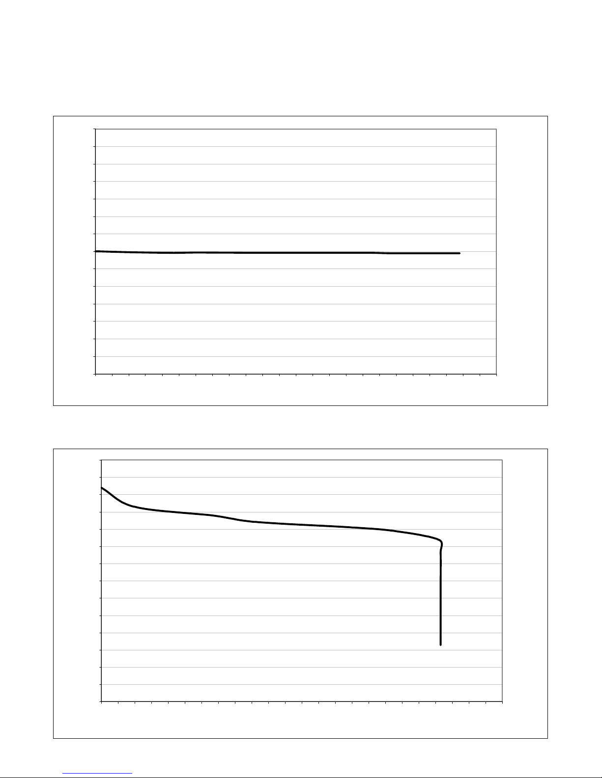
3-5. Volt-Ampere Curves
The volt-ampere curves show the minimum and maximum voltage and amperage output capabilities of the welding power source. Curves of other
settings fall between the curves shown.
A. MIG
70
65
60
55
50
45
40
35
DC Volts
30
25
20
15
10
5
0
0
B. TIG/Stick
70
65
60
55
50
45
40
35
DC Volts
30
25
10 20 30 40 50 60 70 80 90 100 110 120 130 140 150 160 170 180 190 200 210 220 230 240
DC Amperes
20
15
10
5
0
0
10 20 30 40 50 60 70 80 90 100 110 120 130 140 150 160 170 180 190 200 210 220 230 240
DC Amperes
OM-253 918 Page 11
SECTION 4 − INSTALLATION
4-1. Serial Number And Rating Label Location
The serial number and rating information for this product is located on the bottom . Use rating label to determine input power requirements and/or rated
output. For future reference, write serial number in space provided on back cover of this manual.
Operating Temperature Range: 14 F (−10 C) to 104 F (40 C). Ratingt were developed at an ambient temperature of 20 C to 25 C.
4-2. Selecting A Location
! Do not move or operate unit
where it could tip.
1 Line Disconnect Device
Airflow Distance
Requirements
1
460 mm
(18 in.)
Locate unit near correct input power supply.
! Special installation may be
required where gasoline or
volatile liquids are present −
see NEC Article 511 or CEC
Section 20.
460 mm
(18 in.)
Ref. 800 402-A / 956142881_4-A
OM-253 918 Page 12
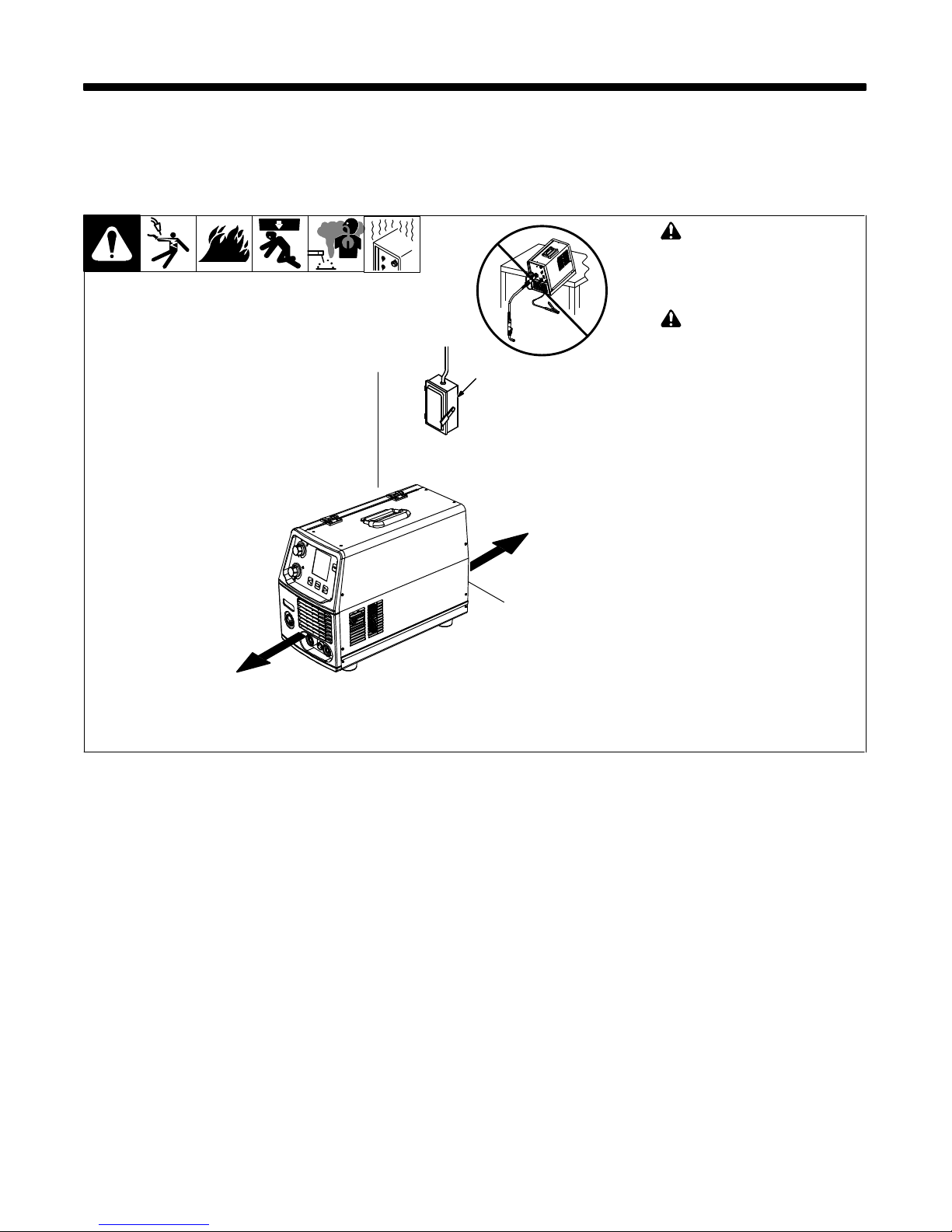
4-3. Installing Gas Supply
7
5
Obtain gas cylinder and chain to
running gear, wall, or other
stationary support so cylinder
cannot fall and break off valve.
1
2
4
Argon Gas Or Mixed Gas
OR
8 9
CO2 Gas
3
1
2
3
1 Cap
2 Cylinder Valve
Remove cap, stand to side of
valve, and open valve slightly. Gas
flow blows dust and dirt from valve.
Close valve.
3 Cylinder
4 Regulator/Flowmeter
Install so face is vertical.
5 Regulator/Flowmeter Gas
Hose Connection
6 Welding Power Source Gas
Hose Connection
Connect supplied gas hose
between regulator/flowmeter gas
hose connection, and fitting on
rear of welding power source.
7 Flow Adjust
Typical flow rate is between 12-15
liters per minute. Check wire
manufacturer’s recommended
flow rate.
8CO2 Adapter (Customer
Supplied)
9 O-Ring (Customer Supplied)
Install adapter with O-ring between
regulator/flowmeter and CO
cylinder.
2
6
Rear Panel
Ref. 149 827-B / Ref. 956142881_1-B
OM-253 918 Page 13
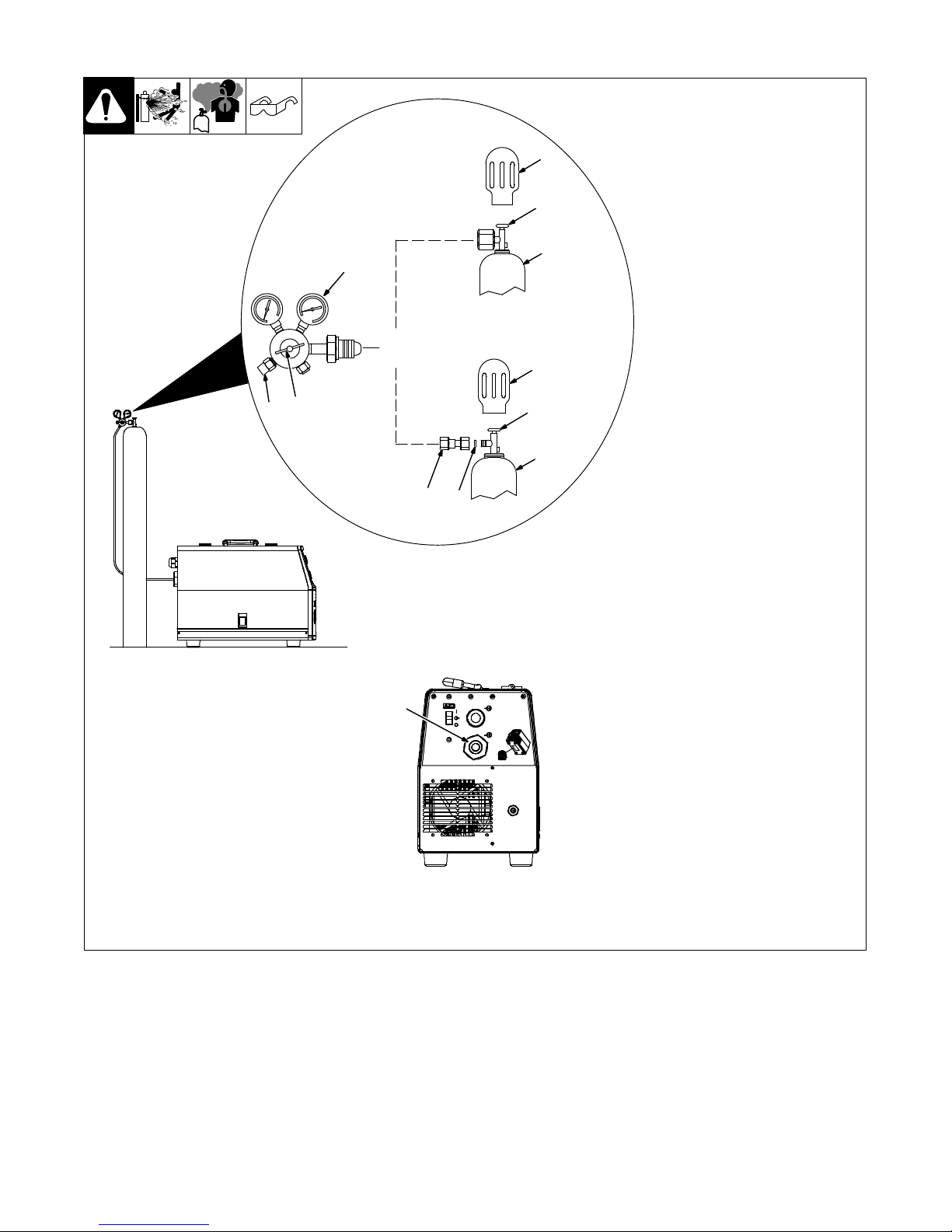
4-4. Weld Output Terminals And Selecting Cable Sizes*
NOTICE − The Total Cable Length in Weld Circuit (see table below) is the combined length of both weld cables. For example, if the power source is
30 m (100 ft) from the workpiece, the total cable length in the weld circuit is 60 m (2 cables x 30 m). Use the 60 m (200 ft) column to determine cable
size.
Weld Cable Size** and Total Cable (Copper) Length in Weld Circuit
Weld Output
Terminals
! Turn off power be-
fore connecting to
weld output terminals.
! Do not use worn,
damaged, undersized, or poorly
spliced cables.
30 m (100 ft) or Less
10 − 60%
mm
Duty
Cycle
2
(AWG)
Welding
Amperes
100 20 (4) 20 (4) 20 (4) 30 (3) 35 (2) 50 (1) 60 (1/0) 60 (1/0)
60 − 100%
Duty
Cycle
2
mm
(AWG)
(150 ft)
Not Exceeding***
45 m
60 m
(200 ft)
70 m
(250 ft)
90 m
(300 ft)
10 − 100% Duty Cycle
2
mm
(AWG)
105 m
(350 ft)
120 m
(400 ft)
150 30 (3) 30 (3) 35 (2) 50 (1) 60 (1/0) 70 (2/0) 95 (3/0) 95 (3/0)
200 30 (3) 35 (2) 50 (1) 60 (1/0) 70 (2/0) 95 (3/0) 120 (4/0) 120 (4/0)
Negative
(−)
* This chart is a general guideline and may not suit all applications. If cable overheats, use next size larger cable.
**Weld cable size is based on either a 4 volts or less drop or a current density of at least 300 circular mils per ampere.
***For distances longer than those shown in this guide, call a factory applications representative. Milan Ref. S-0007-J 2011−07
Positive
(+)
Ref. 956142881_-A
250 35 (2) 50 (1) 60 (1/0) 70 (2/0) 95 (3/0) 120 (4/0)
2x70
(2x2/0)
2x70
(2x2/0)
4-5. Process/Polarity Table
Process Polarity Cable Connections
Cable To Gun Cable To Work
GMAW Solid wire with shielding
gas
FCAW Self-shielding wire and no
shielding gas
DCEP Reverse polarity Connect to positive (+) output ter-
minal
DCEN Straight polarity Connect to negative (−) output
terminal
Connect to negative (−) output
terminal
Connect to positive (+) output terminal
OM-253 918 Page 14
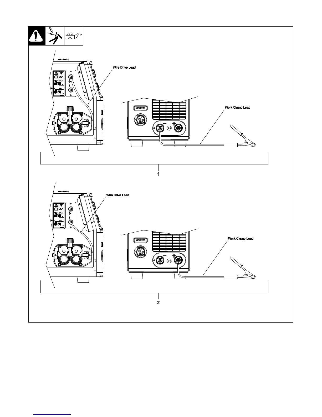
4-6. Changing Polarity
1 Lead Connections For Direct
Current Electrode Positive
(DCEP)
2 Lead Connections For Direct
Current Electrode Negative
(DCEN)
Always read and follow wire
manufacturer’s recommended
polarity and see Section 4-5.
956142881_2-A
OM-253 918 Page 15
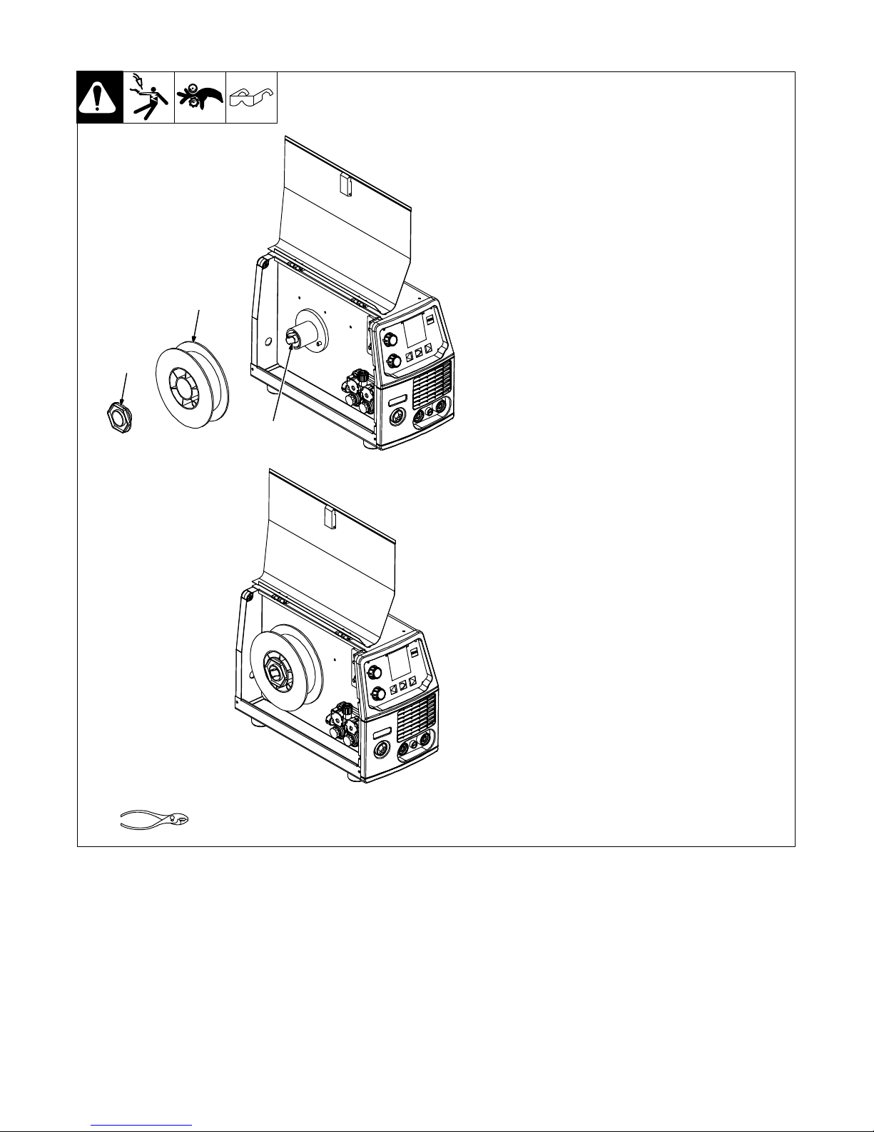
4-7. Installing Wire Spool And Adjusting Hub Tension
1
3
2
1 Wire Spool 5 kg
2 Handwheel
Allows adjustment of hub tension.
Turn handwheel clockwise to increase tension.
3 Spool Holder Cap
Tighten to secure wire spool.
Tools Needed:
OM-253 918 Page 16
956142881_20-B
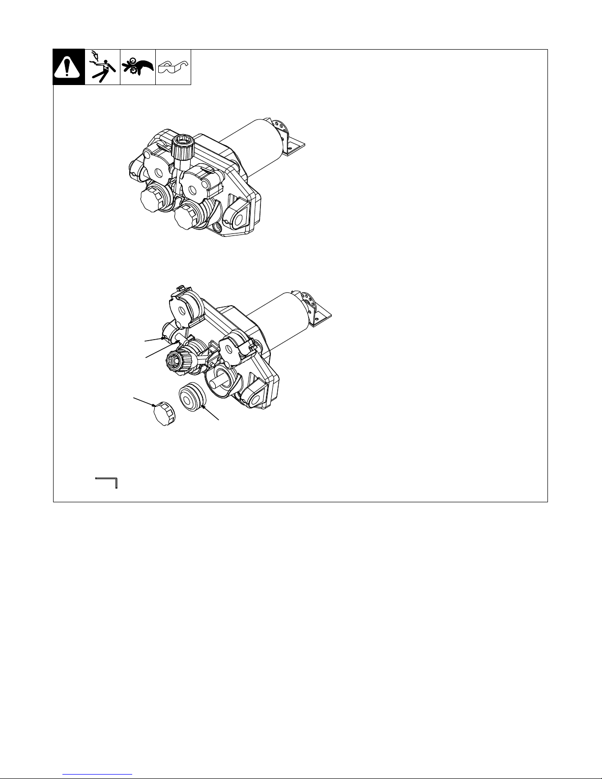
4-8. Changing Drive Rolls And Wire Inlet Guide
1 Setscrew
2 Inlet Wire Guide
Loosen setscrew. Slide tip of guide
as close to drive rolls as possible
without touching. Tighten setscrew.
3 Drive Roll
The drive roll consists of two differ-
ent sized grooves. The stamped
markings on the end surface of the
drive roll refers to the groove on the
opposite side of the drive roll. The
groove closest to the motor shaft is
the proper groove to thread welding
wire.
4 Drive Roll Securing Cap
Turn cap clockwise to secure drive
roll.
Tools Needed:
1
2
4
3
2.5 mm
956142881_19-A
OM-253 918 Page 17
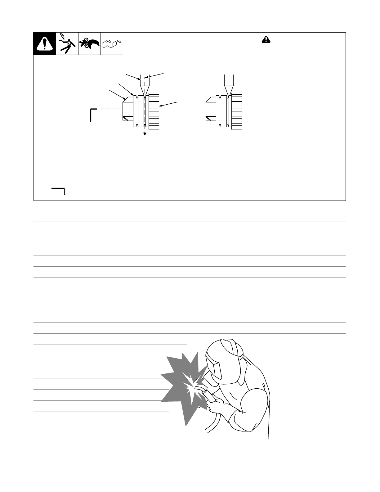
4-9. Aligning Drive Rolls and Wire Guide
Correct Incorrect
3
2
1
Tools Needed:
2.5 mm
4
! Turn off and disconnect in-
put power
View is from top of drive rolls
looking down with pressure
assembly open.
1 Drive Roll Securing Nut
2 Drive Roll
3 Wire Guide
4 Welding Wire
5
5 Drive Gear
Insert screwdriver, and turn screw
in or out until drive roll groove lines
up with wire guide.
Close pressure roll assembly.
Ref. 800 412-A
Notes
Work like a Pro!
Pros weld and cut
safely. Read the
safety rules at
the beginning
of this manual.
OM-253 918 Page 18
 Loading...