

Miller Electric MOTORIZED SLIDE, MSC-2 Owner's Manual

October
1985
FORM:
OM-1096A
OWN
ERS
MANUAL
rnIHEii
.~
MILLER
ELECTRIC
MFG.
CO.
718
S.
BOUNDS
ST.
P.O.
Box
1079
APPLETON,
WI
54912
USA
ADDITIONAL
COPY
PRICE
50
CENTS
IMPORTANT
_____________
Read
and
understand
the
entire
contents
of
both
this
manual
and
the
power
source
manual
used
with
this
unit,
with
special
emphasis
on
the
safety
material
throughout
both
manuals,
before
installing,
peratlng,
or
maintaining
this
equipment.
This
unit
and
these
instructions
are
for
use
only
by
persons
trained
and
experienced
in
the
safe
operation
of
welding
equipment.
Do
not
allow
untrained
persons
to
install,
operate,
or
maintain
this
unit.
Contact
your
dIstributor
If
you
do
not
fully
understand
these
instructions.
Effective
With
Serial
No.
JF.22
MODEL
MOTORIZED
SLIDE
MOTORIZED
SLIDE
CONTROL
MSC-2
NWSA
CODE
NO.
4579
PRINTEDINU.S.A.
LIMITED
WARRANTY
EFFECTIVE:
FEBRUARY
25,
1985
This
warranty
supersedes
all
previous
MILLER
warranties
and
is
ox
clusive
with
no
other
guarantees
or
warranties
expressed
or
implied.
LIMITED
WARRANTY
-
Subject
to
the
terms
and
condi-
In
the
case
of
Millers
breach
of
warranty
or
any
other
duty
I
tions
hereof,
Miller
Electric
Mfg.
Co.,
Appleton,
Wisconsin
with
respect
to
the
quality
of
any
goods,
the
exclusive
remedies
4
warrants
to
its
Distributor/Dealer
that
all
new
and
unused
therefore
shall
be,
at
Millers
option
(1)
repair
or
(2)
replacement
Equipment
furnishedbyMiller
is
free
from
defectinworkman-
or,
where
authorized
in
writing
by
Miller
in
appropriate
cases,
(3)
~
ship
and
material
as
of
the
time
and
place
of
delivery
by
Miller.
the
reasonable
cost
of
repair
or
replacement
at
an
authorized
~.!
No
warranty
is
made
by
Miller
with
respect
to
engines,
trade
Miller
service
station
or
(4)
payment
of
or
credit
for
the
purchase
~
~
accessories
or
other
items
manufactured
by
others.
Such
pnce
(less
reasonable
depreciation
based
upon
actual
use)
upon
~
engines,
trade
accessories
and
other
items
are
sold
subject
to
return
of
the
goods
at
Customers
risk
and
expense.
MILLERs
i~
the
warranties
of
their
respective
manufacturers,
if
any
.
A)l
optionofrepairorreplacement
will
be
FOB.,
Factory,
at
q
engines
are
warranted
by
their
manufacturer
for
one
year
from
Appleton,
Waconsin,orF.O.B.,
at
a
MILLER
authorized
service
~
~
date
of
original
purchase,
except
Tecumseh
engines
which
facility,
therefore,
no
compensation
for
transportation
costs
of
~.
~
have
a
two
year
warranty.
any
kind
will
be
allowed.
Upon
receipt
of
notice
of
apparent
defect
or
failure,
Miller
shall
instruct
the
claimantonthe
warranty
Except
as
specified
below,
Millers
warranty
does
not
apply
claim
procedures
to
be
followed.
to
components
having
normal
useful
life
of
less
than
one
(1)
year,
such
as
spot
welder
tips,
relay
and
contactor
points,
MILLERMATIC
parts
that
come
in
contact
with
the
welding
ANY
EXPRESS
WARRANTY
NOT
PROVIDED
HEREIN
AND
~
wire
including
nozzles
and
nozzle
insulators
where
failure
does
ANY
IMPLIED
WARRANTY,
GUARANTY
OR
REPRESENTA
~
not
result
from
defect
in
workmanship
or
material.
TION
AS
TO
PERFORMANCE,
AND
ANY
REMEDY
FOR
BREACH
OF
CONTRACT
WHICH,
BUT
FOR
THIS
PROVISION,
Miller
shall
be
required
to
honor
warranty
claims
on
war-
MIGHT
ARISE
BY
IMPLICATION,
OPERATION
OF
LAW.
~
~
ranted
Equipment
in
the
event
of
failure
resulting
from
a
defect
CUSTOM
OF
TRADE
OR
COURSE
OF
DEALING,
INCLUDING
~.
~
within
the
following
periods
from
the
date
of
delivery
of
Equip-
ANY
IMPLIED
WARRANTY
OF
MERCHANTABILITY
OR
OF
~
~
ment
to
the
original
user:
FITNESS
FOR
PARTICULAR
PURPOSE,
WITH
RESPECT
TO
ANY
AND
ALL
EQUIPMENT
FURNISHED
BY
MILLER
IS
EX
1.
Arc
welders,
power
sources
and
components
....
1
year
CLUDED
AND
DISCLAIMED
BY
MILLER.
r~
2.
Original
main
power
rectifiers
3
years
(labor
-
1
year
only)
3.
Allweldingguns,feeder/gunsandplasmatorches...
90days
EXCEPT
AS
EXPRESSLY
PROVIDED
BY
MILLER
IN
4.
All
other
Millermatic
Feeders
1
year
WRITING,
MILLER
PRODUCTS
ARE
INTENDED
FOR
5.
Replacement
or
repair
parts,
exclusive
of
labor
..
60
days
ULTIMATE
PURCHASE
BY
COMMERCIAL/INDUSTRIAL
~
6.
Batteries
6
months
USERS
AND
FOR
OPERATION
BY
PERSONS
TRAINED
AND
4
EXPERIENCED
IN
THE
USE
AND
MAINTENANCE
OF
?
provided
that
Millerisnotified
in
writing
within
thirty
(30)
days
WELDING
EQUIPMENT
AND
NOT
FOR
CONSUMERS
OR
of
the
date
of
such
failure.
CONSUMER
USE.
MILLERS
WARRANTIES
DO
NOT
EXTEND
~
r~
. .
.
TO,
AND
NO
RESELLER
IS
AUTHORIZED
TO
EXTEND
~
submitted
by
the
ori~nal
user
wittun
the
foregoing
periods
MILLERS
WARRANTIES
TO,
ANY
CONSUMER.
~
~
~
~
ji
~,
~
~
~
~ ~
J~
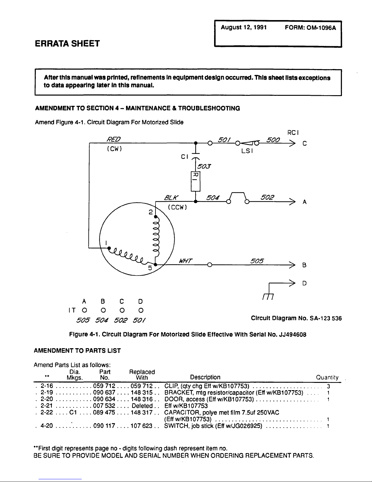
ERRATA
SHEET
r
After
this
manual
was
printed,
refinements
In
equipment
design
occurred.
This
sheet
lists
exceptions
to
data
appearing
laterInthis
manual.
AMENDMENT
TO
SECTION
4
MAINTENANCE
&
TROUBLESHOOTING
Amend
Figure
4-1.
Circuit
Diagram
For
Motorized
Slide
Figure
4-1.
Circuit
Diagram
For
Motorized
Slide
Effective
With
Serial
No.
JJ494608
AMENDMENT
TO
PARTS
LIST
**Fjrst
digit
represents
page
no
-
digits
following
dash
represent
item
no.
BE
SURE
TO
PROVIDE
MODEL
AND
SERIAL
NUMBER
WHEN
ORDERING
REPLACEMENT
PARTS.
RED
(CW)
Cl
RC
I
LS
I
C
A
B
D
A
B
C
0
ITO
0
0 0
505
504
502
50/
147
Amend
Parts
List
as
follows:
Dia.
Part
**
Mkgs.
No.
Circuit
Diagram
No.
SA-1
23
536
Replaced
With
Description
.
2-16
059712...
.059712.
.
.
2-19
090637...
.148315.
.
.
2-20
090634...
.148316.
.
.
2-21
007
532..
.
.
Deleted.
.
.
2-22
.
..
.C1
.
. .
.089475...
.148317.
.
4-20
090117..
Quantity
CLIP,
(qty
chg
Efl
w/KB107753)
BRACKET,
mtg
resistor/capacitor
(Eff
w/KB107753)
DOOR,
access
(Elf
w/KB1
07753)
Elf
w/KB1
07753
CAPACITOR,
polye
met
film
7.5uf
250
VAC
(Elf
w/KB107753)
107
623..
SWITCH,
job
stick
(Eff
w/JG026925)
.3

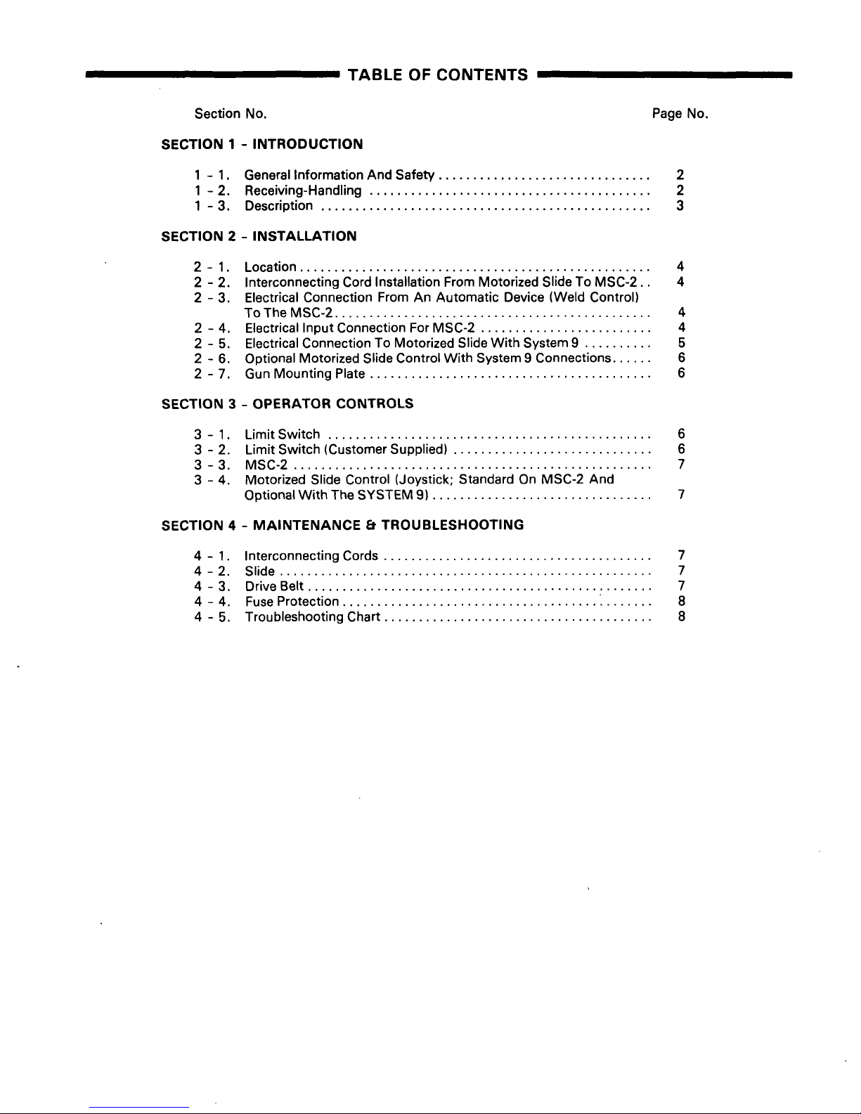
TABLE
OF
CONTENTS
Section
No.
Page
No.
SECTION
1
-
INTRODUCTION
1
-
1.
General
Information
And
Safety
2
1
-
2.
Receiving-Handling
2
1
-
3.
Description
3
SECTION
2-INSTALLATION
2-1.
Location
4
2
-
2.
Interconnecting
Cord
Installation
From
Motorized
Slide
To
MSC-2
4
2
-
3.
Electrical
Connection
From
An
Automatic
Device
(Weld
Control)
To
The
MSC-2
4
2
-
4.
Electrical
Input
Connection
For
MSC-2
4
2
-
5.
Electrical
Connection
To
Motorized
Slide
With
System
9 5
2
-
6.
Optional
Motorized
Slide
Control
With
System
9
Connections
6
2
-
7.
Gun
Mounting
Plate
6
SECTION
3
-
OPERATOR
CONTROLS
3
-
1.
Limit
Switch
6
3
-
2.
Limit
Switch
(Customer
Supplied)
6
3-3.
MSC-2
7
3
-
4.
Motorized
Slide
Control
(Joystick;
Standard
On
MSC-2
And
Optional
With
The
SYSTEM
9)
7
SECTION
4
-
MAINTENANCE
&
TROUBLESHOOTING
4
-
1.
Interconnecting
Cords
7
4-2.
Slide
7
4
-
3.
Drive
Belt
7
4-4.
Fuse
Protection
8
4
-
5.
Troubleshooting
Chart
8

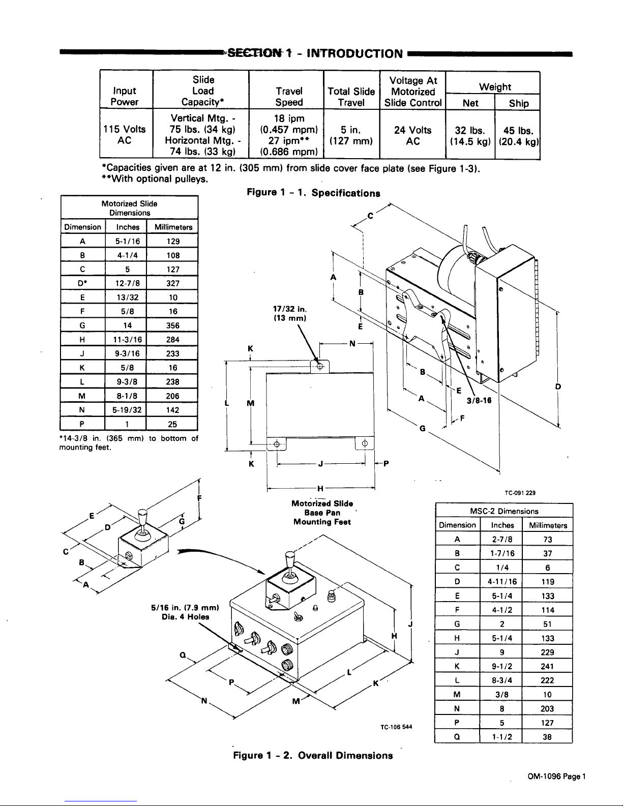
SEeBONt
-
INTRODUCTION
Input
Power
Slide
Load
Capacity*
Travel
Speed
Total
Slide
Travel
Voltage
At
Motorized
Slide
Control
ht
eig
Net
Ship
115
Volts
AC
Vertical
Mtg.
-
75
lbs.
(34
kg)
Horizontal
Mtg.
-
74
lbs.
(33
kg)
18
ipm
(0.457
mpm)
27
ipm**
(0.686
mpm)
5
in.
(127
mm)
24
Volts
AC
32
lbs.
(14.5
kg)
45
lbs.
(20.4
kg)
*Capacities
given
are
at
12
in.
**With
optional
pulleys.
(305
mm)
from
slide
cover
face
plate
(see
Figure
1-3).
Figure
1
-
1.
Specifications
Motorized
Slide
Dimensions
Dimension
Inches
Millimeters
A
5-1/16
129
B 4-1/4
108
C
5
127
0
12-7/8
327
E
13/32
10
F
5/8
16
G
14
356
H
11-3/16
284
J
9-3/16
233
K
5/8
16
L
9-3/8
238
M
8-1/8
206
N
5-19/32
142
P
1
25
14-3/8
in.
mounting
feet.
(365
mm)
to
bottom
of
MSC-2
Dimensions
Dimension
Inches
Millimeters
A
2-7/8
73
B
1-7/16
37
C
1/4
6
D
4-11/16
119
E
5-1/4
133
F
4-1/2
114
G
2
51
H
5-1/4
133
J
9
229
K
9-1/2
241
L
8-3/4
222
M
3/8
10
N
8
203
P
5
127
Q
1-1/2
38
Motorized
Slide
Base
Pan
Mounting
Feet
TC-091
229
a
TC-106
544
Figure
1
-
2.
Overall
Dimensions
OM-1096
Page
1
 Loading...