

Miller Electric MO-200/200 Owner's Manual
June
1976
FORM:
OM-803B
Effective
with
Serial
No.
MEHG003288
MODEL
MO200/200
STOCK
NO.
041
070
MODEL/STOCK
NO.
SERIAL/STYLE
NO.
DATE
PURCHASED
ADDITI:ONAL
COPY
PRICE
:~O
CENTS
OWNERS
MANUAL
MILLER
ELECTRIC
MFG.
CO.
APPLETON,
WISCONSIN,
USA
54911
NWSA
CODE
NO.
4579
,.l~e~TtO
0.90.
LIMITED
WARRANTY
MILLER
Electric
Mfg.
Co.,
Appleton,
Wisconsin,
warrants
all
new
equipment
to
be
free
from
defects
in
material
and
factory
workmanship
for
the
periods
indicated
below,
provided
the
equipment
is
installed
and
operated
according
to
manufacturers
instructions.
MILLER
Electric
Mfg.
Co.s
obligation,
underthis
warranty,
is
expressly
limited
to
replacing
or
repairing
any
defective
part
or
correcting
any
manufacturing
defect
without
charge
during
the
warranty
period
if
MILLERS
inspection
confirms
the
existenceofsuch
defects.
MILLERS
option
of
repair
or
replacement
will
be
f.o.b.
factory
at
Appleton,
Wisconsin
or
f.o.b.aMILLER
authorized
service
facility,
and
therefore
c
no
compensation
for
transportation
costs
of
any
kind
willbeallowed.
The
warranty
period,
beginning
on
the
date
of
sale
to
the
original
prchaser.user
of
the
equipment,
will
be
as
follows:
c
1.
Arc
welders,
power
sources,
and
components
1
year
2.
Original
main
power
rectifiers
3
years
(unconditionally)
3.
20E,
20K,
and
all
welding
guns~
90
days
4.
All
other
Millermatic
Feeders
1
year
5.
All
engines
1
year
Engine
Warranties
are
covered
by
the
engine
manufacturers,
subject
to
their
procedures
andtobe
handled
?
through
their
authorized
local
Service
Stations
or
agencies.
No
warranty
will
be
made
in
respect
to
trade
accessories,
such
being
subject
to
the
warranties
of
their
respective
manufacturers.
MILLER
Electric
Mfg.
Co.
will
not
be
liable
for
any
loss
or
consequential
damage
or
expense
accruing
directlyorindirectly
from
the
use
of
equipment
covered
in
this
warranty.
,
C
C,
This
warranty
supersedes
all
previous
MILLER
warranties
andisexclusive
with
no
other
guarantees
or
C
warranties
expressed
or
implied.
SECTION
1
-
INTRODUCTION
1-1.
GENERAL
This
manual
has
been
prepared
especially
for
use
in
familiar
izing
personnel
with
the
design,
installation,
operation,
main
tenance,
and
troubleshooting
of
this
equipment.
All
informa
tion
presented
herein
should
be
given
careful
consideration
to
assure
optimum
performance
of
this
equipment.
Prior
to
installing
this
equipment,
clean
all
packing
material
from
around
the
Unit
and
carefully
inspect
for
any
damage
that
may
have
occurred
during
shipment.
Any
claims
for
loss
or
damage
that
may
have
occurred
in
transit
must
be
filed
by
the
purchaser
with
the
carrier.
A
copy
of
the
bill
of
lading
and
freight
bill
will
be
furnished
by
the
carrier
on
request
if
occasiontofile
claim
arises.
When
requesting
information
concerning
this
equipment,
it
is
essential
that
Model
Description
and/or
Stock
Number
and
Serial
(or
Style)
Numbers
of
the
equipment
be
supplied.
1-3.
DESCRIPTION
This
unit
is
designed
to
function
as
a
two
operator
welding
control
station
which
is
remotely
located
from
the
welding
power
source.
This
unit
is
equipped
with
two
output
ELEC
TRODE
receptacles.
The
output
at
each
ELECTRODE
recep
tacle
is
governed
by
a
separate
set
of
amperage
controls.
This
welding
control
station
is
protected
from
damage
due
to
ex
ces~ive
overload
by
a
fuse
in
the
input
circuitry.
1-4.
SAFETY
The
following
definition
applies
to
IMPORTANT
blocks
found
throughout
this
manual.
SECTION
2
-
INSTALLATION
2-1.
LOCATION
A
good
installation
is
essentialifthe
welding
control
station
is
to
provide
satisfactory
and
dependable
service.
Proper
operating
temperatures
are
maintained
by
the
air
stream
pass
ing
through
the
unit.
IMPORTANT
The
welding
control
station
should
be
located
so
that
the
side
panels
with
the
air
vents
or
louvers
are
clear
of
any
obstruction.
The
location
should
be
such
that
a
minimum
amount
of
dust
and
dirt
will
be
drawn
into
the
air
stream.
Preventive
main
tenance
consists
of
removing
the
wrapper
from
the
welding
control
station
and
blowing
out
the
dust
accumulation
inside
the
unit.
2-2.
INPUT
AND
OUTPUT
CONNECTIONS
A
male
Camlock
plug
is
provided
on
the
rear
panel
of
the
welding
control
station
for
connecting
the
electrode
cable
from
the
welding
power
source.
The
Corresponding
female
receptacle
for
this
camlock
plug
is
Supplied
with
the
welding
control
station.
Two
female
Camlock
receptacles
are
provided
on
the
front
panel
of
the
welding
control
Station
for
making
connections
from
the
Station
to
the
electrode
holder
cables.
The
corres
ponding
male
Camlock
receptacles
are
Supplied
with
the
weld
ing
station.
Use
Table
2-1
as
a
guide
in
selecting
the
electrode
holder
cable.
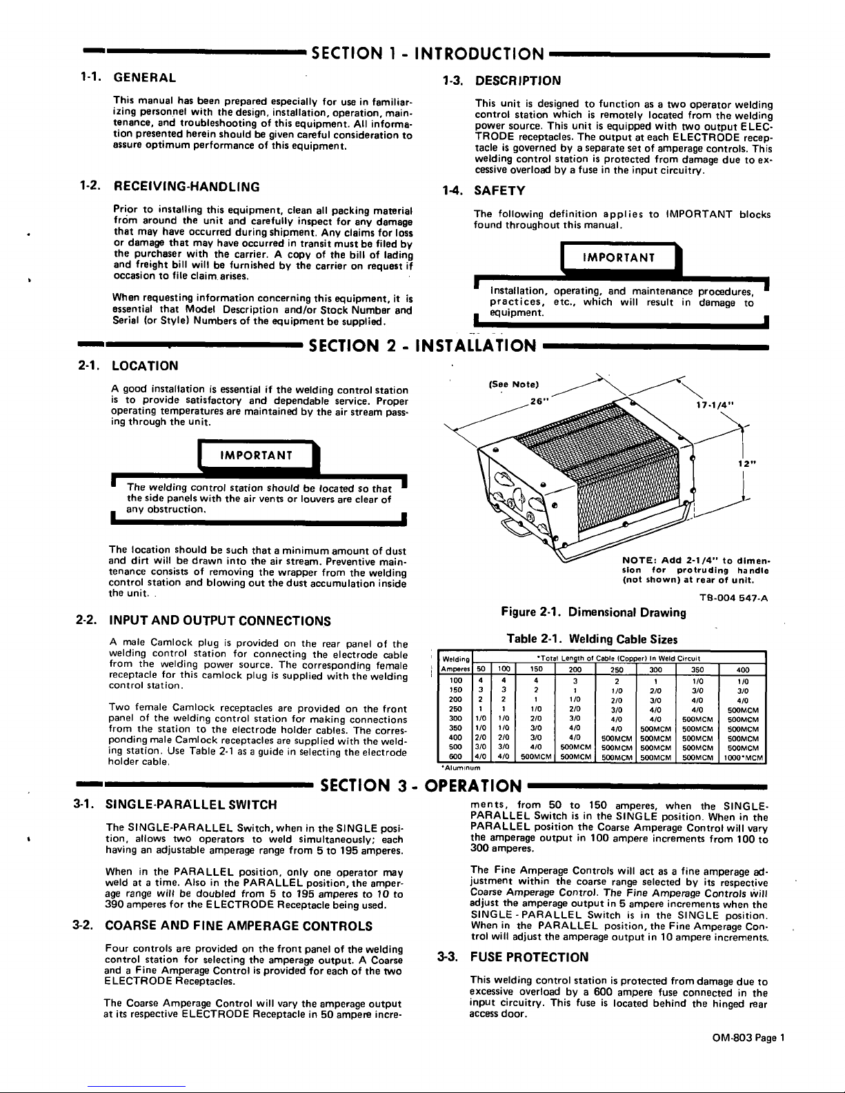
Figure
2-1.
Dimensional
Drawing
Table
2-1
-
Welding
Cable
Sizes
TB-004
547-A
Woldinp
Tota
Cable
lCopn
sri
In
Weld
Circuit
Amperes
50
100
150
200
250
300
350
400
100
4
4
4
3
2
1
1/0
1/0
150
3
3
2
I
I/O
2/0
3/0
3/0
200
2
2
1
1/0
2/0 3/0
4/0
4/0
250
1 1
1/0
2/0
3/0
4/0
4/0
500MCM
300
1/0
1/0
2/0
3/0
4/0
4/0
500MCM
500MCM
350
1/0 1/0
3/0
4/0
4/0
500MCM
500MCM
500MCM
400
2/0
2/0
3/0
4/0
SOOMCM
500MCM
500McM
SOOMCM
500
3/0 3/0
4/0
500MCM
500MCM
500MCM
500MCM
500MCM
600
4/0 4/0
500MCM
500MCM
500MCM 500McM 500MCM
1000MCM
Aluminum
SECTION
3
-
OPERATION
3-1
-
SINGLE-PARALLEL
SWITCH
The
SINGLE-PARALLEL
Switch,
when
in
the
SINGLE
posi
tion,
allows
two
operators
to
weld
simultaneously;
each
having
an
adjustable
amperage
range
from
5to195
amperes.
When
in
the
PARALLEL
position,
only
one
operator
may
weld
at
a
time.
Also
in
the
PARALLEL
position,
the
amper
age
range
will
be
doubled
from
5
to
195
amperes
to10to
390
amperes
for
the
ELECTRODE
Receptacle
being
used.
3-2.
COARSE
AND
FINE
AMPERAGE
CONTROLS
Four
controls
are
provided
on
the
front
panel
of
the
welding
control
station
for
selecting
the
amperage
output.
A
Coarse
and
a
Fine
Amperage
Control
is
provided
for
eachofthe
two
ELECTRODE
Receptacles.
The
Coarse
Amperage
Control
will
vary
the
amperage
output
at
its
respective
ELECTRODE
Receptacle
in
50
ampere
incre
ments,
from
50
to
150
amperes,
when
the
SINGLE-
PARALLEL
Switch
is
in
the
SINGLE
position.
When
in
the
PARALLEL
position
the
Coarse
Amperage
Control
will
vary
the
amperage
output
in
100
ampere
increments
from
100
to
300
amperes.
The
Fine
Amperage
Controls
will
act
as
a
fine
amperage
ad
justment
within
the
coarse
range
selected
by
its
respective
Coarse
Amperage
Control.
The
Fine
Amperage
Controls
will
adjust
the
amperage
output
in
5
ampere
increments
when
the
SINGLE
-
PARALLEL
Switch
is
in
the
SINGLE
position.
When
in
the
PARALLEL
position,
the
Fine
Amperage
Con
trol
will
adjust
the
amperage
output
in
10
ampere
increments.
3-3.
FUSE
PROTECTION
This
welding
control
station
is
protected
from
damage
due
to
excessive
overload
by
a
600
ampere
fuse
connected
in
the
input
circuitry.
This
fuse
is
located
behind
the
hinged
rear
access
door.
1-2.
RECEIVING-HANDLING
I
IM~T
Installation,
operating,
and
maintenance
procedures,~
practices,
etc.,
which
will
result
in
damage
to
equipment.
NOTE:
Add
2-1/4
to
dimen
sion
for
protruding
handle
(not
shown)
at
rear
of
unit.
OM-803
Page
1
 Loading...