

Miller Electric MMT-210A Owner's Manual
March
1974
FORM:
OM-1024
ADDITIONAL
COPY
PRICE
25
CENTS
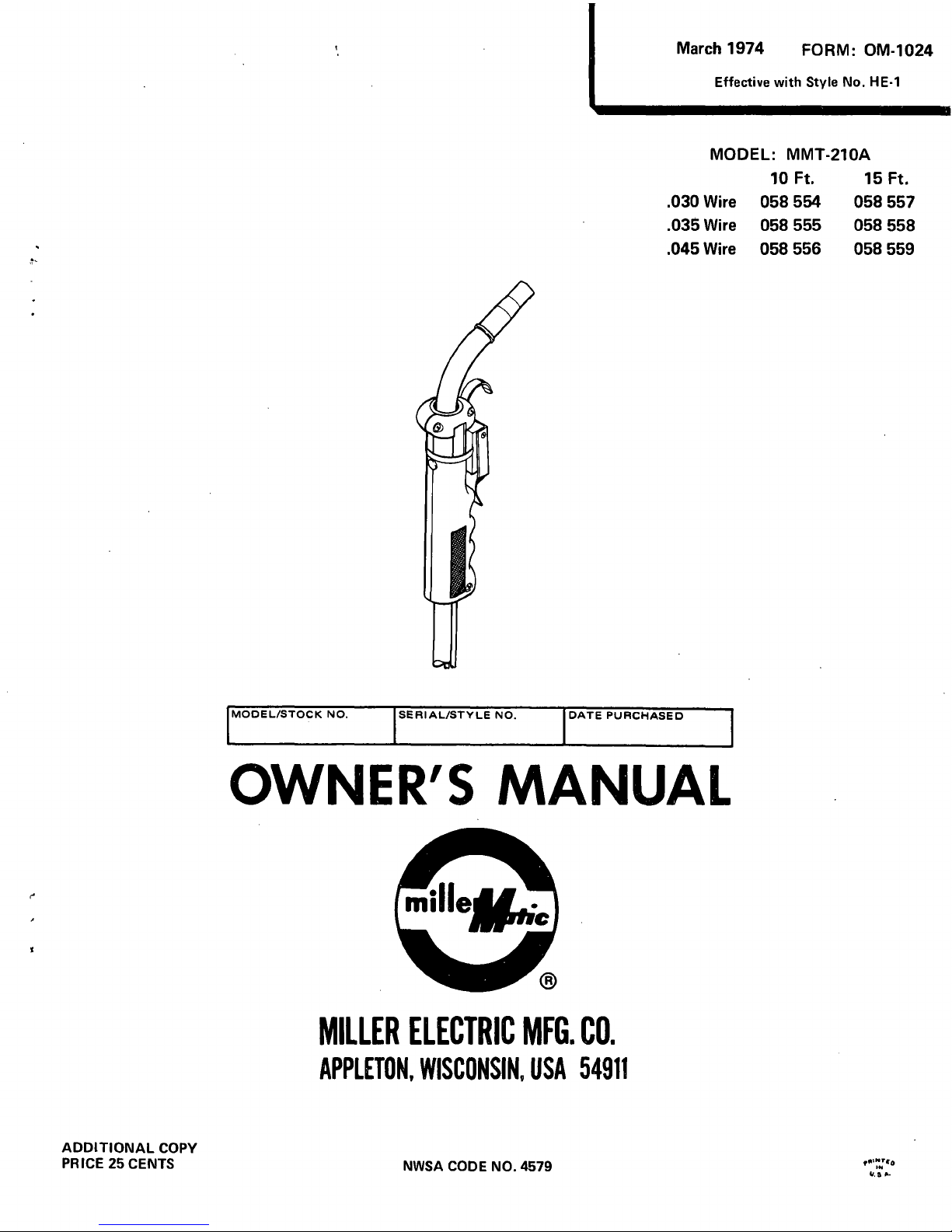
.030
Wire
.035
Wire
.045
Wire
MODEL/STOCK
NO.
SERIAL/STYLE
NO.
DATE
PURCHASED
OWNERS
MANUAL
MILLER
ELECTRIC
MFG.
CO.
APPLETON,
WISCONSIN,
USA
54911
10
Ft.
058
554
058
555
058
556
15
Ft.
058
557
058
558
058
559
Effective
with
Style
No.
HE-i
MODEL:
MMT-210A
NWSA
CODE
NO.
4579
U
5
5.
~1
1kJU&J(
M(
X
LXYJ(_X
LX
LLXJ&JULX
X
X
LLLX
LJ&$
C
b
oT~
OTfl
p
nT~O~t
~fti~T6
~ 8
r8T8T81T6
P
oTo~T~TPT~bt~8TPTooTPTflTPT
C
~
C)
C
~
C)
C
~
CD
C)
C)
CD
WARRANTY
MILLER
Electric
Mfg.
Co.,
Appleton,
Wisconsin,
warrants
all
new
equipment
to
be
free
from
defects
in
material
and
factory
workmanship
for
the
periods
indicated
below,
provided
the
equipment
is
installed
and
C
)
CD
operated
according
to
manufacturers
instructions.
CD
CD
CD
MILLER
Electric
Mfg.
Co.s
obligation,
under
this
warranty,
is
limited
to
replacingorrepairing
any
defective
part
or
correcting
any
manufacturing
defect
without
charge
during
the
warranty
period
if
MILLERS
inspec-
C
)
C)
tion
confirms
the
existenceofsuch
defects.
MILLERS
optionofrepair
or
replacement
will
bef.o.b.
factory
at
c
Appleton,
Wisconsin
or
f.o.b.aMILLER
authorized
service
facility,
and
therefore
no
compensation
for
trans
I
~
portationcostsofanykindwillbeallowed.
C)
C)
The
warranty
period,
beginning
on
the
date
of
sale
to
the
original
purchaser-user
of
the
equipment,
will
be
as
I
~
follows:
c
1
Arc
welders,
power
sources,
and
components
1
year
C
C)
2.
Original
main
power
rectifiers
3
years
(unconditionally)
3.
MHFC-L1
Feeder,
MHG-35C1,
20E,
20K,
C
I
~
CD
and
all
guns
and
torches
90
days
c )
4.
All
other
Millermatic
Feeders
1
year
5.
Mag-Diesel
engine
on
DEL-200
6
months
C
C)
U
~
6.
All
other
engines
1
year
c
U
C)
Engine
Warranties
are
covered
by
the
engine
manufacturers,
subject
to
their
procedures
and
to
be
handled
C)
through
their
authorized
local
Service
Stations
or
agencies.
No
warranty
will
be
made
in
respect
to
trade
accessories,
such
being
subject
to
the
warranties
of
their
respective
manufacturers.
C
I
U
C)
I
)
-
C)
U
U
C)
MILLER
Electric
Mfg.
Co.
will
not
be
liable
for
any
loss
or
consequential
damage
or
expense
accruing
c
directlyorindirectly
from
the
use
of
equipment
covered
in
this
warranty.
U
U
C
~
U
U
C)
I
This
warranty
supersedes
all
previous
MILLER
warranties
and
is
exclusive
with
no
other
guarantees
or
C
U
U
C)
U
warranties
expressed
or
implied.
c
U
U
C)
_______________________________________________________________
Q
QptQ
Q1.Q..P.JPQLRJ..i
P
P
Q9
QLQ
ro~romro
crom
SECTION
1
-
INTRODUCTION
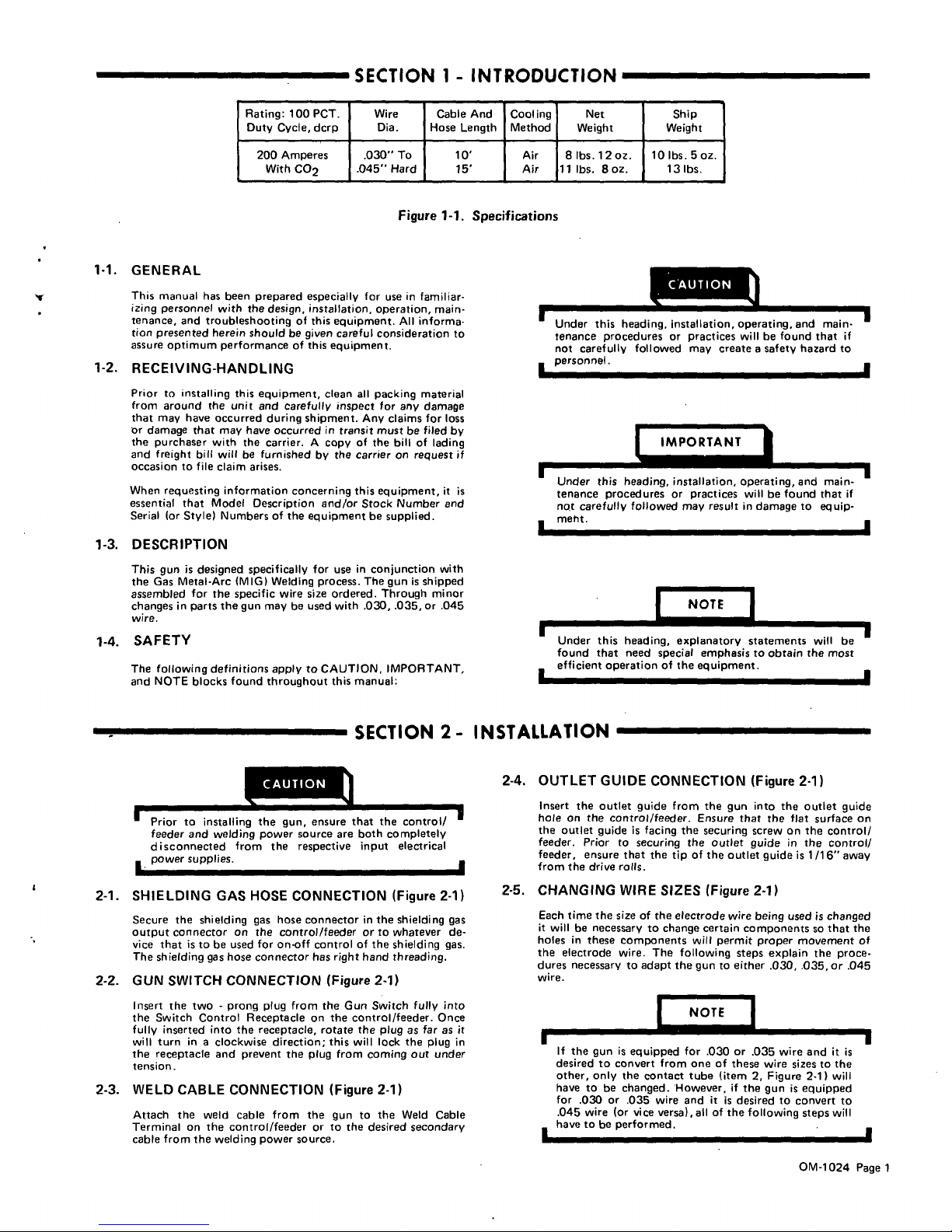
Rating:
100
PCT.
Duty
Cycle,
dcrp
Wire
Dia.
Cable
And
Hose
Length
Cooling
Method
Net
Weight
Ship
Weight
200
Amperes
.030
To
10
Air
8
lbs.
12
oz.
10
lbs.
5
oz.
With
CO2
.045
Hard
15
Air
11
lbs.
8oz,
13
lbs.
Figure
1-1.
Specifications
1-1.
GENERAL
This
manual
has
been
prepared
especially
for
use
in
familiar.
izing
personnel
with
the
design,
installation,
operation,
main
tenance,
and
troubleshooting
of
this
equipment.
All
informa
tion
presented
herein
should
be
given
careful
consideration
to
assure
optimum
performance
of
this
equipment.
1-2.
RECEIVING-HANDLING
Prior
to
installing
this
equipment,
clean
all
packing
material
from
around
the
unit
and
carefully
inspect
for
any
damage
that
may
have
occurred
during
shipment.
Any
claims
for
loss
or
damage
that
may
have
occurred
in
transit
must
be
filed
by
the
purchaser
with
the
carrier.
A
copy
of
the
bill
of
lading
and
freight
bill
willbefurnished
by
the
carrier
on
request
if
occasion
to
file
claim
arises.
When
requesting
information
concerning
this
equipment,
it
is
essential
that
Model
Description
and/or
Stock
Number
and
Serial
(or
Style)
Numbers
of
the
equipmentbesupplied.
1-3.
DESCRIPTION
This
gun
is
designed
specifically
for
use
in
conjunction
with
the
Gas
Metal-Arc
(MIG)
Welding
process.
The
gun
is
shipped
assembled
for
the
specific
wire
size
ordered.
Through
minor
changes
in
parts
the
gun
may
be
used
with
.030, .035.
or
.045
wire.
1-4.
SAFETY
The
following
definitions
apply
to
CAUTION,
IMPORTANT,
and
NOTE
blocks
found
throughout
this
manual:
this
h
eading,
installation,
operating
,
a
nd
main
tenance
procedures
or
practices
will
be
found
that
if
not
carefully
followed
may
create
a
safety
hazard
to
personnel.
fl~ORT~T
Under
this
heading,
installation,
operating,
and
main
tenance
proceduresorpractices
will
be
found
that
if
no,t
carefully
followed
may
result
in
damage
to
equip
meht.
I~..r=~-1
.1
Under
this
heading,
explanatory
statements
will
be
found
that
need
special
emphasis
to
obtain
the
most
efficient
operation
of
the
equipment.
SECTION
2-
INSTALLATION
CAUTION_-~
Prior
to
installing
the
gun,
ensure
t~econtrol/
feeder
and
welding
power
source
are
both
completely
disconnected
from
the
respective
input
electrical
power
supplies.
2-4.
OUTLET
GUIDE
CONNECTION
(Figure
2-1)
Insert
the
outlet
guide
from
the
gun
into
the
outlet
guide
hole
on
the
control/feeder.
Ensure
that
the
flat
surface
on
the
outlet
guide
is
facing
the
securing
screw
on
the
control/
feeder.
Prior
to
securing
the
outlet
guide
in
the
control/
feeder,
ensure
that
the
tip
of
the
outlet
guide
is
1/16
away
from
the
drive
rolls.
2-1.
SHIELDING
GAS
HOSE
CONNECTION
(Figure
2-1)
Secure
the
shielding
gas
hose
connector
in
the
shielding
gas
output
connector
on
the
control/feeder
or
to
whatever
de
vice
that
istobe
used
for
on-off
control
of
the
shielding
gas.
The
shielding
gas
hose
connector
has
right
hand
threading.
2-2.
GUN
SWITCH
CONNECTION
(Figure
2-1)
Insert
the
two
-
prong
plug
from
the
Gun
Switch
fully
into
the
Switch
Control
Receptacle
on
the
control/feeder.
Once
fully
inserted
into
the
receptacle,
rotate
the
plug
as
far
as
it
will
turn
in
a
clockwise
direction;
this
will
lock
the
plug
in
the
receptacle
and
prevent
the
plug
from
coming
out
under
tension.
2-3.
WELD
CABLE
CONNECTION
(Figure
2-1)
Attach
the
weld
cable
from
the
gun
to
the
Weld
Cable
Terminal
on
the
control/feeder
or
to
the
desired
secondary
cable
from
the
welding
power
source.
2-5.
CHANGING
WIRE
SIZES
(Figure
2-1)
Each
time
the
size
of
the
electrode
wire
being
used
is
changed
it
will
be
necessary
to
change
certain
components
so
that
the
holesinthese
components
will
permit
proper
movement
of
the
electrode
wire.
The
following
steps
explain
the
proce
dures
necessary
to
adapt
the
gun
to
either
.030, .035,
or
.045
wire.
U
~OTE
~
U
If
the
gun
is
equipped
for
.030
or
035
wire
and
it
is
desired
to
convert
from
one
of
these
wire
sizes
to
the
other,
only
the
contact
tube
(item
2,
Figure
2-1)
will
have
to
be
changed.
However,
if
the
gun
is
equipped
for
.030
or
.036 wire
and
it
is
desired
to
convert
to
.045
wire
(Or
vice
versa),
allofthe
following
steps
will
haveto
be
performed,
.
OM-1024
Page
1
 Loading...