

Miller Electric Gas Cylinder Rack, Mixed Gas Regulator 300237 Owner's Manual
OWNER’S MANUAL
FORM: OM-230806A 2007−11
Use above FORM number when ordering extra manuals.
Gas Cylinder Rack/Mixed Gas Regulator 300237 for Renegadet 180
NOTICE − Lift Eye Kit 195353 CAN NOT be installed when this kit is installed.
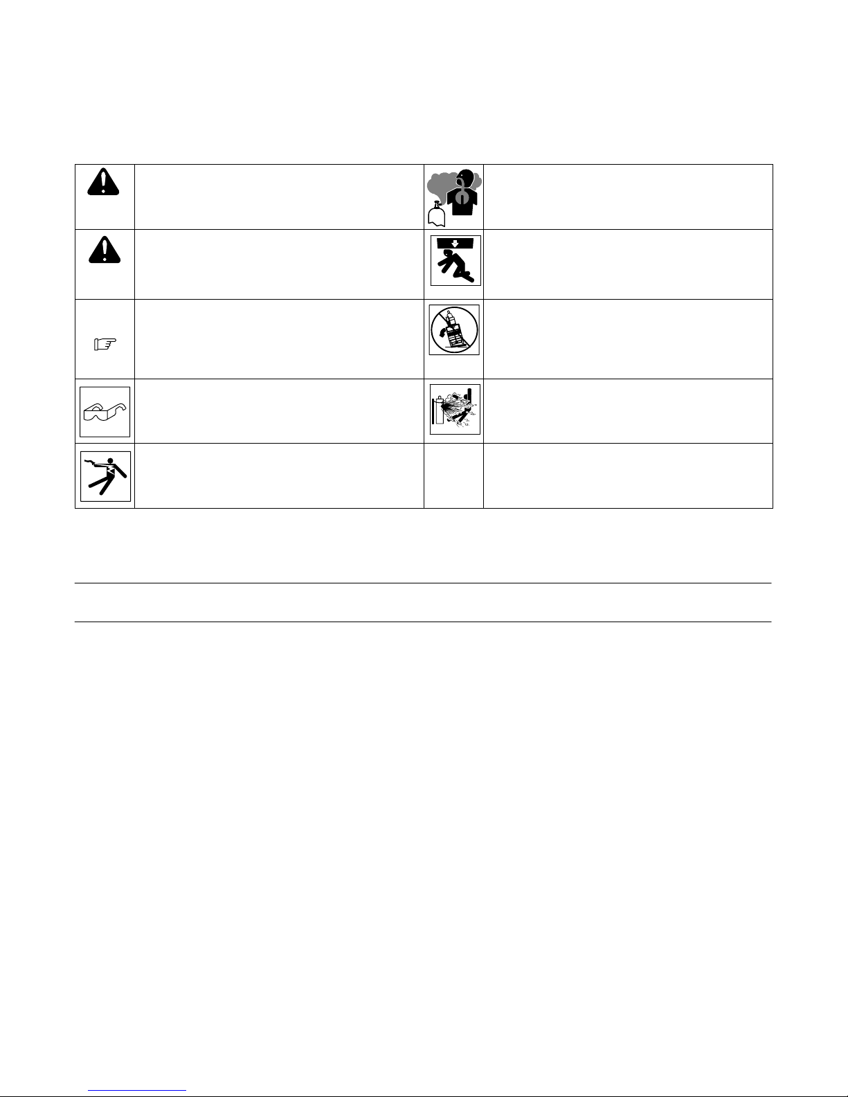
1. Safety Symbol Definitions
DANGER! − Indicates a hazardous situation which, if not
avoided, will result in death or serious injury. The possible
hazards are shown in the adjoining symbols or explained
in the text.
Indicates a hazardous situation which, if not avoided,
could result in death or serious injury. The possible hazards are shown in the adjoining symbols or explained in
the text.
NOTICE
Indicates statements not related to personal injury.
Indicates special instructions.
Wear safety glasses with side shields. Cylinders contain gas under high pressure and can ex-
Beware of electric shock from wiring. Stop engine and
disconnect negative (−) cable from battery before installing this kit. Reinstall all panels and covers.
2. Parts List
Item
No.
Part
No.
Description
Build-up of gas can injure or kill. Shut off shielding gas
supply when not in use. Always ventilate confined spaces
or use approved air-supplied respirator.
Falling equipment can cause serious personal injury and
equipment damage. Do not lift unit with cylinder
installed on rack. Lift and support only with proper
equipment and correct procedures.
Tipping equipment can cause injury and damage
equipment. Do not move cart where two wheels are at
different heights and cart could tip − avoid tipping. Be
careful when moving unit over uneven surfaces. Do not
use an oversized cylinder or exceed maximum cylinder
weight.
plode if damaged. Never let a welding electrode touch
any cylinder. Always secure cylinder to running gear, wall,
or other stationary support.
Quantity
300237
Gas Cylinder Rack/Regulator
1 229713 Bracket, Mtg Gas Bottle Lower 1. . . . . . . . . . . . . . . . . . . . . . . . . . . . . . . . . . . . . . . . . . . . . . . . . . . . . . . .
2 229714 Bracket, Mtg Gas Bottle Side 1. . . . . . . . . . . . . . . . . . . . . . . . . . . . . . . . . . . . . . . . . . . . . . . . . . . . . . . . .
3 229715 Bracket, Mtg Gas Bottle Upper 1. . . . . . . . . . . . . . . . . . . . . . . . . . . . . . . . . . . . . . . . . . . . . . . . . . . . . . . .
4 230765 Strap, Retaining Cylinder Gas 1. . . . . . . . . . . . . . . . . . . . . . . . . . . . . . . . . . . . . . . . . . . . . . . . . . . . . . . . .
5 601941 Screw, 250−20x1.75 Hexwhd.61d Gr5 Pld 5. . . . . . . . . . . . . . . . . . . . . . . . . . . . . . . . . . . . . . . . . . . . . .
6 152461 Nut, 250−20 .44hex .23h Stl Pld Sem Cone Wshr.65d 5. . . . . . . . . . . . . . . . . . . . . . . . . . . . . . . . . . . .
7 602154 Screw, 250−20x .50 Hexwhd.50d Stl Pld Slffmg Tap−rw 4. . . . . . . . . . . . . . . . . . . . . . . . . . . . . . . . . .
8 221037 Regulator/Flowmeter, 10−50 Cfh Argon/CO2 1. . . . . . . . . . . . . . . . . . . . . . . . . . . . . . . . . . . . . . . . . . . .
9 229566 Hose, Gas 7 Ft 1. . . . . . . . . . . . . . . . . . . . . . . . . . . . . . . . . . . . . . . . . . . . . . . . . . . . . . . . . . . . . . . . . . . . . .
10 223861 Clip, Edge W/Cable Tie 4. . . . . . . . . . . . . . . . . . . . . . . . . . . . . . . . . . . . . . . . . . . . . . . . . . . . . . . . . . . . .
11 230796 Label, Warning Oversized Cyl/Falling Eq 1. . . . . . . . . . . . . . . . . . . . . . . . . . . . . . . . . . . . . . . . . . . . . .
12 230797 Label, Warning Oversized Cyl/Falling Eq (Sp) 1. . . . . . . . . . . . . . . . . . . . . . . . . . . . . . . . . . . . . . . . . .
13 113786 Welding Wire, Stl Hard .030 4” Spool 2lbs ER70S−61. . . . . . . . . . . . . . . . . . . . . . . . . . . . . . . . . . . .
BE SURE TO PROVIDE MODEL AND SERIAL NUMBER WHEN ORDERING REPLACEMENT PARTS.
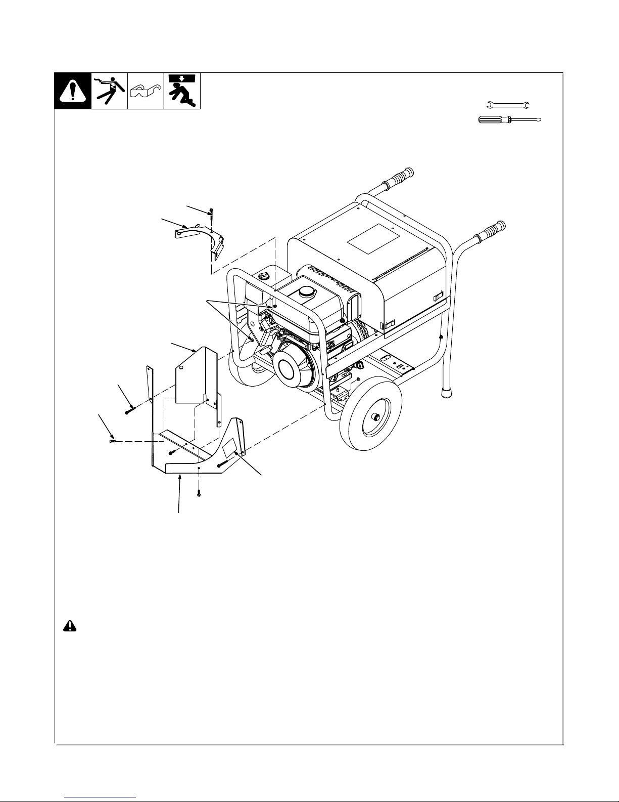
3. Installing Cylinder Rack And Gas Hose
3
5
4
Tools Needed:
6
3
7
2
Stop engine and let cool or disconnect utility input power.
1 Warning Label
2 Lower Gas Bottle Mounting Bracket
Apply one warning label to each side of the
mounting bracket.
3 1/4−20 x 1.75 in. Screw
1
Maximum Cylinder Weight = 80 lb (36.3 kg)
Maximum Cylinder Diameter = 7 in. (178 mm)
Maximum Cylinder Height = 48 in. (1220 mm)
4 1/4−20 Nut
5 Upper Gas Bottle Mounting Bracket
Install lower mounting bracket using sup-
plied 1/4−20 hardware. If using gas cylinders with a safety strap height greater than
24 in. (610 mm), install upper gas bottle
mounting bracket using supplied 1/4-20
hardware.
6 Side Gas Bottle Mounting Bracket
7 1/4−20 x .5 in Screw
If using gas cylinders with a safety strap
height less than 24 in. (610 mm), install
side mounting bracket using supplied
1/4−20 screws.
OM-230 806 Page 2
804 723-B
 Loading...