

Miller Electric MILLERMATIC 3OAN Owner's Manual
January
1979
FORM:
OM-1234A
Effective
With
Serial
No.
HJ171707
MODEL
MILLERMATIC
3OAN
CONTROL/FEEDER
OWN
ERS
MANUAL
rAllIER
MILLER
ELECTRIC
MFG.
CO.
718
S.
BOUNDS
ST.
P.O.
Box
1079
APPLETON,
WI
54912
USA
ADDITIONAL
COPY
PRICE
65
CENTS
NWSA
CODE
NO.
4579
PRINTED
IN
U.S.A.
--
LIMITED
WARRANTY
EFFECTIVE:
FEBRUARY
20,
1978
This
warranty
supersedes
all
previous
MILLER
warranties
and
is
ex
clusive
with
no
other
guarantees
or
warranties
expressed
or
implied.
LIMITED
WARRANTYMiller
Electric
Mfg.
Co.,
Apple-
1.
Arc
welders,
power
sources,
and
components.
.
1
year
ton,
Wisconsin
warrants
to
Customer
that
all
rrew
and
unused
2.
Original
main
power
rectifiers
3
years
Equipment
furnished
by
Miller
is
free
from
defect
in
(Labor
1
year
only)
workmanship
and
materialasof
the
time
and
place
of
3.
All
welding
guns
and
feeder/guns
90
days
delivery
by
Miller.
No
warranty
is
made
by
Miller
with
respect
to
engines,
trade
accessories
or
other items
manu-
4.
All
other
Millermatic
Feeders
1
year
factured
by
others.
Such
engines,
trade
accessories
and
other
provided
that
the
user
so
notifies
Miller
in
writing
within
thirty
items
are
sold
subject
to
the
warranties
of
their
respective
(30)
days
of
the
dateofsuch
failure.
manufacturers,
if
any.
The
manufacturers
warranty
on
5.
Replacementorrepair
parts
exclusive
of
labor
60
days
engines
is
for
a
period
of
one
year.
MILLER
warranty
does
not
apply
to
components
having
ANY
EXPRESS
WARRANTY
NOT
PROVIDED
normal
useful
life
of
less
than
one
(1)
year,
such
as
spot
HEREIN
AND
ANY
IMPLIED
WARRANTY,
GUARANTY
welder
tips,
relay
and
contactor
points,
MILLERMATIC
OR
REPRESENTATION
AS
TO
PERFORMANCE,
AND
parts
that
come
in
contact
with
the
welding
wire
including
ANY
REMEDY
FOR
BREACH
OF
CONTRACT
WHICH,
nozzles
and
nozzle
insulators
where
failure
does
not
result
BUT
FOR
THIS
PROVISION.
MIGHT
ARISE
BY
from
defect
in
workmanship
or
material.
IMPLICATION.
OPERATION
OF
LAW,
CUSTOM
OF
TRADE
OR
COURSE
OF
DEALING,
INCLUDING
ANY
In
the
case
of
Millers
breach
of
warranty
or
any
other
duty
with
respect
to
the
quality
of
any
goods,
the
exclusive
IMPLIED
WARRANTY
OF
MERCHANTABILITY
OR
OF
remedies
therefor
shall
be.
at
Millers
option,
(1)
repair
or
(2)
FITNESS
FOR
PARTICULAR
PURPOSE.
WITH
RESPECT
replacement
or.
where
authorized
in
writing
by
Miller
in
TO
ANY
AND
ALL
EQUIPMENT
FURNISHED
BY
appropriate
cases,
(3)
the
reasonable
cost
of
repair
or
MILLER
IS
EXCLUDED
AND
DISCLAIMED
BY
MILLER.
replacement
at
an
authorized
Miller
service
station
or
(4)
payment
of
or
credit
for
the
purchase
price
(less
reasonable
EXCEPT
AS
EXPRESSLY
PROVIDED
BY
MILLER
IN
depreciation
based
upon
actual
use)
upon
return
of
the
goods
WRITING,
MILLER
PRODUCTS
ARE
INTENDED
FOR
at
Customers
risk
and
expense.
All
transactions
are
F.O.B.
ULTIMATE
PURCHASE
BY
COMMERCIAL/INDUSTRIAL
Appleton,
Wisconsin.
Upon
receipt
of
notice
of
apparent
USERS
AND
FOR OPERATION
BY
PERSONS
TRAINED
defect
or
failure,
Miller
shall
instruct
the
claimant
on
the
AND
EXPERIENCED
IN
THE
USE
AND
MAINTENANCE
warranty
claim
procedures
to
be
followed.
OF
WELDING
EQUIPMENT
AND
NOT,
FOR
CONSUMERS
As
a
matter
of
general
policy
only,
Miller
may
honor
an
OR
CONSUMER
USE.
MILLER
WARRANTIES
DO
NOT
original
users
warranty
claimsonwarranted
Equipment
in
EXTEND
TO,
AND
NO
RESELLER
IS
AUTHORIZED
TO
the
event
of
failure
resulting
from
a
defect
within
the
following
periods
from
the
date
of
delivery
of
Equipment
to
EXTEND
MILLERS
WARRANTIES
TO,
ANY
the
original
user:
CONSUMER.
TABLE
OF
CONTENTS
Section
No.
Page
No.
SECTION
1
INTRODUCTION
1
-
1.
General
1
1-2.
Receiving-Handing
1
1
-
3.
Description
1
1-4.
Safety
1
SECTION
2
INSTALLATION
2-1.
Location
1
2-2.
Drive
Motor
1
2-3.
Shielding
Gas
Connections
2
2
-
4.
Water
Connections
2
2
-
5.
115
Volts
AC
Connections
2
2-6.
Contactor
Control
Connections
2
2-7.
Switch
Control
Connections
2
2
-
8.
Weld
Cable
Terminal
2
2
-
9.
Speed
Change
Gears
2
2-10.
Wire
Guide
&
Drive
Roll
Installation
3
2-1
1.
Spindle
Assembly
Installation
3
2-12.
Installation
Of
Spool-Type
Wire
3
2-13.
Installation
Of
Wire
Reel
3
2-14.
Installation
of
Reel-Type
Wire
3
2-15.
Adjusting
Hub
Tension
4
2-16.
Welding
Wire
Threading
4
SECTION
3
FUNCTION
OF
CONTROLS
3-
1.
Power
Switch
5
3-2.
Wire
Speed
Control
5
3
-
3.
Remote
Control
Receptacle
&
Switch
5
3-
4.
Purge
Button
5
3
-
5.
Inch
Switch
5
3-6.
Start
Switch
5
3-7.
Retract-Feed
Switch
5
3-8.
Reset
Circuit
Breaker
5
SECTION
4
SEQUENCE
OF
OPERATION
4-
1.
Gas
Metal-Arc
Welding
(GMAW)
5
4
-
2.
Shutting
Down
5
SECTION
5
MAINTENANCE
5-
1.
Inspection
And
Upkeep
6
5
-
2.
Cleaning
Of
Drive
Roll
Bearings
6
5-3.
Fuse
6
SECTION
6
TROUBLESHOOTING
SECTION
7
DATA
CHARTS

SECTION
1
-
INTRODUCTION
Electrode
Wire
Dia.
Capability
Electrode
Wre
Feed
Speed
Control
Circuit
Voltage
At
Gun
Overall
Dimensions
(Inches)
Weight
(Pounds)
Net
Ship
.030
-
1/8
20
to
900
1pm.
~
24
Volts
Height
-
24-1/2
Width
-14-3/4
Depth
-34-1/4
66
71
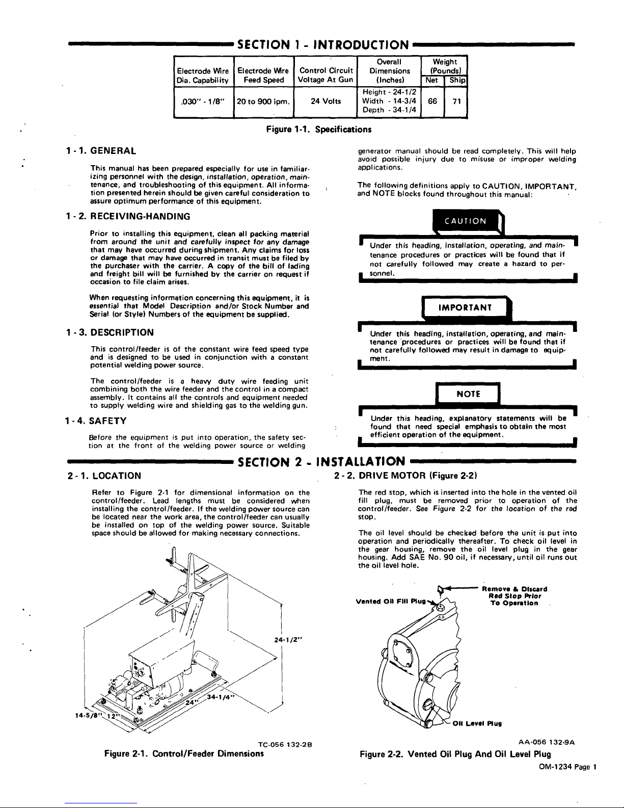
Figure
1-1.
Specifications
1
-
1.
GENERAL
This
manual
has
been
prepared
especially
for
use
in
familiar
izing
personnel
with
the
design,
installation,
operation,
main
tenance,
and
troubleshooting
of
this
equipment.
All
informa
tion
presented
herein
should
be
given
careful
consideration
to
assure
optimum
performance
of
this
equipment.
1-2.
RECEIVING-HANDING
Prior
to
installing
this
equipment,
clean
all
packing
material
from
around
the
unit
and
carefully
inspect
for
any
damage
that
may
have
occurred
during
shipment.
Any
claims
for
loss
or
damage
that
may
have
occurred
in
transit
must
be
filed
by
the
purchaser
with
the
carrier.
A
copy
of
the
bill
of
lading
and
freight
bill
will
be
furnishedbythe
carrier
on
request
if
occasion
to
file
claim
arises.
When
requesting
information
concerning
this
equipment,
it
is
essential
that
Model
Description
and/or
Stock
Number
and
Serial
(or
Style)
Numbers
of
the
equipment
be
supplied.
1
-
3.
DESCRIPTION
This
control/feeder
is
of
the
constant
wire
feed
speed
type
and
is
designed
to
be
used
in
conjunction
with
a
constant
potential
welding
power
source.
The
control/feeder
is
a
heavy
duty
wire
feeding
unit
combining
both
the
wire
feeder
and
the
control
in
a
compact
assembly.
It
contains
all
the
controls
and
equipment
needed
to
Supply
welding
wire
and
shielding
gas
to
the
welding
gun.
1
-4.
SAFETY
Before
the
equipment
is
put
into
operation,
the
safety
sec
tionatthe
front
of
the
welding
power
source
or
welding
generator
manual
shouldberead
completely.
This
will
help
avoid
possible
injury
due
to
misuse
or
improper
welding
applications.
The
following
definitions
applytoCAUTION,
IMPORTANT,
and
NOTE
blocks
found
throughout
this
manual:
I
I
~this
heading,
installation,
operating,
and
main-
1
tenance
procedures
or
practices
will
be
found
that
if
not
carefully
followed
may
create
a
hazard
to
per
sonnel.
rTA~I
Under
this
heading,
installation,
operating,
and
main
tenance
procedures
or
practices
will
be
found
that
if
not
carefully
followed
may
result
in
damage
to
equip
ment.
Under
this
heading,
explanatory
statements
will
be
found
that
need
special
emphasis
to
obtaIn
the
most
efficient
operation
of
the
equipment.
SECTION
2
-
INSTALLATION
2-1.
LOCATION
Refer
to
Figure
2-1
for
dimensional
information
on
the
control/feeder.
Lead
lengths
must
be
considered
when
installing
the
control/feeder.
If
the
welding
power
source
can
be
located
near
the
work
area,
the
control/feeder
can
usually
be
installed
on
top
of
the
welding
power
source.
Suitable
space
shouldbeallowed
for
making
necessary
Connections.
2-2.
DRIVE
MOTOR
(Figure
2-2)
The
red
stop,
whichisinserted
into
the
holeinthe
vented
oil
fill
plug.
must
be
removed
priortooperation
of
the
control/feeder.
See
Figure
2-2
for
the
location
of
the
red
stop.
The
oil
level
shouldbechecked
before
the
unit
is
put
into
operation
and
periodically
thereafter.Tocheck
oil
level
in
the
gear
housing,
remove
the
oil
level
plug
in
the
gear
housing.
Add
SAE
No.
90
oil,
if
necessary,
until
oil
runs
out
the
oil
level
hole.
Remove
&
Discard
Red
Stop
Prior
To
Opsratlon
AA-056
132-9A
Figure
2-2.
Vented
Oil
Plug
And
Oil
Level
Plug
TC-056
132-28
Figure
2-1
-
Control/Feeder
Dimensions
Levil
Plug
OM-1234
Page
1
2
-3.
SHIELDING
GAS
CONNECTIONS
(Figure
2-4)
Determine
the
distance
the
control/feeder
is
to
be
located
from
the
shielding
gas
supply,
and
connect
a
hose
from
the
regulator-flowmeter
on
the
gas
supply
to
the
gas
fitting
on
the
rear
of
the
control/feeder.
This
connection
has
a
right-hand
thread.
The
shielding
gas
hose
which
comes
from
the
gun
is
to
be
attached
to
the
gas
connector
on
the
front
panel
of
the
control/feeder.
This
connector
has
a
right-hand
thread.
2
-4.
WATER
CONNECTIONS
(Optional)
(Figure
3-1)
When
a
water-cooled
gun
is
used,
connect
a
hose
from
the
water
supply
to
the
WATER
IN
fitting
on
the
rear
of
the
control/feeder.
This
fitting
has
a
left-hand
thread.
See
the
gun
Instruction
Martual
for
gun
to
control/feeder
connec
tions.
Route
the
return
water
where
desired.
connections.
When
the
switch
connected
across
this
recep
tacle
is
closed,
the
contactor
in
the
welding
power
source
will
energize,
shielding
gas
will
flow,
and
wire
will
begin
to
feed.
2-
8.
WELD
CABLE
TERMINAL
A
terminal
is
provided
on
the
base
of
the
control/feeder
to
serve
as
a
junction
point
for
joining
together
the
weld
cables
from
the
welding
power
source
and
the
gun.
IMPORTANT
Ensure
that
the
weld
cable
terminal
is
kept
clean
at
all
times.
Also
ensure
that
the
nut
on
this
terminal
is
secure.
If
either
one
of
the
above
conditions
is
not
met,
erratic
weld
current
may
result.
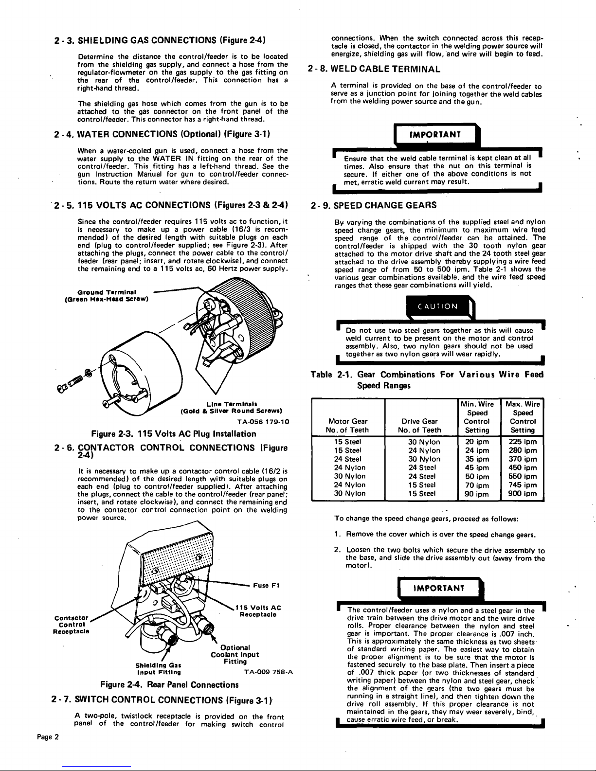
2-5.115
VOLTS
AC
CONNECTIONS
(Figures2-3&2-4)
2-9.
SPEEDCHANGEGEARS
Since
the
con~ol/feeder
requires
115
volts
ac
to
function,
it
is
necessary
to
make
upapower
cable
(16/3
is
recom
mended)
of
the
desired
length
with
suitable
plugs
on
each
end
(plug
to
control/feeder
supplied;
see
Figure
2-3).
After
attaching
the
plugs,
connect
the
power
cabletothe
control/
feeder
(rear
panel;
insert,
and
rotate
clockwise),
and
connect
the
remaining
end
to
a
115
volts
ac,
60
Hertz
power
supply.
Figure
2-3.
115
Volts
AC
Plug
Installation
2-6.
CONTACTOR
CONTROL
CONNECTIONS
(Figure
2-4)
It
is
necessary
to
make
up
a
contactor
control
cable
(16/2
is
recommended)
of
the
desired
length
with
suitable
plugs
on
each
end
(plug
to
control/feeder
supplied).
After
attaching
the
plugs,
connect
the
cabletothe
control/feeder
(rear
panel;
insert,
and
rotate
clockwise),
and
connect
the
remaining
end
to
the
contactor
control
connection
point
on
the
welding
power
source.
Optional
Coolant
Input
Fitting
TA-009
758-A
Figure
2-4.
Rear
Panel
Connections
2-7.
SWITCH
CONTROL
CONNECTIONS
(Figure
3-1)
A
two-pole,
twistlock
receptacle
is
provided
on
the
front
panel
of
the
control/feeder
for
making
switch
control
By
varying
the
combinations
of
the
supplied
steel
and
nylon
speed
change
gears,
the
minimum
to
maximum
wire
feed
speed
range
of
the
control/feeder
can
be
attained.
The
control/feeder
is
shipped
with
the
30
tooth
nylon
gear
attached
to
the
motor
drive
shaft
and
the
24
tooth
steel
gear
attached
to
the
drive
assembly
thereby
supplying
a
wire
feed
speed
range
of
from
50
to
500
ipm.
Table
2-1
shows
the
various
gear
combinations
available,
and
the
wire
feed
speed
ranges
that
these
gear
combinations
will
yield.
L~
~use
two
steel
gears
together
~s
will
cause
weld
current
to
be
present
on
the
motor
and
control
assembly.
Also,
two
nylon
gears
should
not
be
used
together
as
two
nylon
gears
will
wear
rapidly.
Table
2-1.
Gear
Combinations
For
Various
Wire
Feed
Speed
Ranges
Motor
Gear
No.
of
Teeth
Drive
Gear
No.ofTeeth
Mm.
Wire
Speed
Control
Setting
Max.
Wire
Speed
Control
Setting
15
Steel
15
Steel
24
Steel
24
Nylon
30
Nylon
24
Nylon
30
Nylon
30
Nylon
24
Nylon
30
Nylon
24
Steel
24
Steel
15
Steel
15
Steel
20
ipm
24
1pm
35
ipm
45
ipm
50
ipm
70
ipm
90
ipm
225
ipm
280
ipm
370
1pm
450
ipm
550
1pm
745
ipm
900
1pm
To
change
the
speed
change
gears,
proceed
as
follows:
1.
Remove
the
cover
which
is
over
the
speed
change
gears.
2.
Loosen
the
two
bolts
which
secure
the
drive
assembly
to
the
base,
and
slide
the
drive
assembly
Out
(away
from
the
motor).
IMPORTANT
The
control/feeder
uses
a
nylon
and
a
steel
gear
in
the
drive
train
between
the
drive
motor
and
the
wire
drive
rolls.
Proper
clearance
between
the
nylon
and
steel
gear
is
important.
The
proper
clearanceis.007
inch.
This
is
approximately
the
same
thickness
as
two
sheets
of
standard
writing
paper.
The
easiest
way
to
obtain
the
proper
alignment
istobe
sure
that
the
motor
is
fastened
securely
to
the
base
plate.
Then
insert
a
piece
of
.007
thick
paper
(or
two
thicknesses
of
standard
writing
paper)
between
the
nylon
and
steel
gear,
check
the
alignment
of
the
gears
(the
two
gears
must
be
running
in
a
straight
line),
and
then
tighten
down
the
drive
roll
assembly,
If
this
proper
clearance
is
not
maintained
in
the
gears,
they
may
wear
severely,
bind,
cause
erratic
wire
feed,
or
break.
Ground
Terminal
(Green
Hex-Head
Screw)
I
LIne
Terminals
(Gold
&
Sliver
Round
Screws)
TA-056
179-10
Contactor
Control
Receptacle
Fuse
Fl
115
Volts
AC
Receptacle
Shielding
Gas
Input
Fitting
Page
2
3.
Using
a
1/8
inch
allen
wrench,
loosen
the
set
screw
in
the
gear
on
the
drive
assembly,
and
remove
the
gear.
4.
Loosen
the
set
screw
in
the
gear
on
the
motor
drive
shaft,
and
remove
the
gear.
5.
Slide
the
desired
gear
onto
the
drive
assembly,
and
tighten
the
set
screw
in
the
gear.
6.
Slide
the
desired
gear
onto
the
motor
drive
shaft,
and
tighten
the
set
screw
in
the
gear.
7.
Install
the
cover
over
the
speed
change
gears.
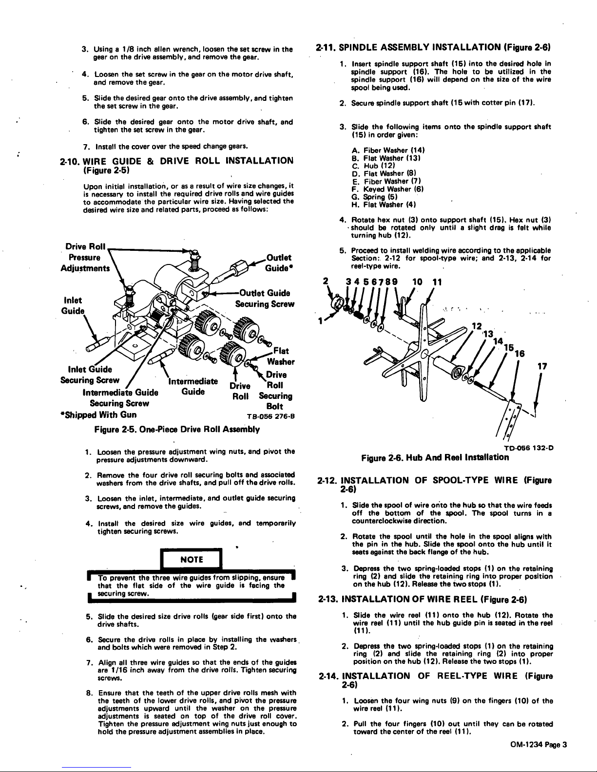
2-10.
WIRE
GUIDE
&
DRIVE
ROLL
INSTALLATION
(Figure
2-5)
Upon
initial
installation,
or
as a
result
of
wire
size
changes,
it
is
necessary
to
install
the
required
drive
rolls
and
wire
guides
to
accommodate
the
particular
wire
size.
Having
selected
the
desired
wire
size
and
related
parts,
proceed
as
follows:
Washer
Inlet
Drive
Securing
Screw
R
II
Intermediate
Guide
Guide
Roll
Securing
Securing
Screw
Bolt
Shipped
With
Gun
TB-056
276-B
Figure
2-5.
One-Piece
Drive
Roll
Assembly
1.
Loosen
the
pressure
adjustment
wing
nuts,
and
pivot
the
pressure
adjustments
downward.
2.
Remove
the
four
drive
roll
securing
bolts
and
associated
washers
from
the
drive
shafts,
and
pull
off
the
drive
rolls.
3.
Loosen
the
inlet,
intermediate,
and
outlet
guide
securing
screws,
and
remove
the
guides.
4.
Install
the
desired
size
wire
guides,
and
temporarily
tighten
securing
screws.
NOTE
To
prevent
the
three
wire
guides
from
slipping,
ensure
that
the
flat
sideofthe
wire
guideisfacing
the
securing
screw.
5.
Slide
the
desired
size
drive
rolls
(gear
side
first)
onto
the
drive
shafts.
6.
Secure
the
drive
rolls
in
place
by
installing
the
washers
and
bolts
which
were
removed
in
Step
2.
7.
Align
all
three
wire
guides
so
that
the
ends
of
the
guides
are
1/16
inch
away
from
the
drive
rolls.
Tighten
securing
screws.
8.
Ensure
that
the
teeth
of
the
upper
drive
rolls
mesh
with
the
teeth
of
the
lower
drive
rolls,
and
pivot
the
pressure
adjustments
upward
until
the
washer
on
the
pressure
adjustments
is
seated
on
top
of
the
drive
roll
cover.
Tighten
the
pressure
adjustment
wing
nuts
just
enough
to
hold
the
pressure
adjustment
assemblies
in
place.
2-11.
SPINDLE
ASSEMBLY
INSTALLATION
(Figure
2-6)
1.
Insert
spindle
support
shaft
(15)
into
the
desired
hole
In
spindle
support
(16).
The
hole
to
be
utilized
in
the
spindle
support
(16)
will
depend
on
the
size
of
the
wire
spool
being
used.
2.
Secure
spindle
support
shaft
(15
with
cotter
pin
(17).
3.
Slide
the
following
items
onto
the
spindle
support
shaft
(15)
in
order
given:
A.
Fiber
Washer
(14)
B.
Flat
Washer
(13)
C.
Hub
(12)
0.
FIat
Washer
(8)
E.
Fiber
Washer
(7)
F.
Keyed
Washer
(6)
G.
Spring
(5)
H.
Flat
Washer
(4)
4.
Rotate
hex
nut
(3)
onto
support
shaft
(15).
Hex
nut
(3)
-
should
be
rotated
only
until
a
slight
drag
is
felt
while
turning
hub
(12).
5.
Proceedtoinstall
welding
wire
according
to
the
applicable
Section:.
2.12
for
spool-type
wire;
and
2-13,
2-14
for
reel-type
wire.
456789
10
11
TD-056
132-0
Figure
2-6.
Hub
And
Reel
Installation
2-12.
INSTALLATION
OF
SPOOL-TYPE
WIRE
(Figure
2-6)
1.
Slide
the
spool
of
wire
onto
the
hub
so
that
the
wire
feeds
off
the
bottom
of
the
spool.
The
spool
turns
in
a
counterclockwise
direction.
2.
Rotate
the
spool
until
the
hole
in
the
spool
aligns
with
the
pin
in
the
hub.
Slide
the
spool
onto
the
hub
until
It
seats
against
the
back
flange
of
the
hub.
3.
Depress
the
two
spring-loaded
stops
(1)
on
the
retaining
ring
(2)
and
slide
the
retaining
ring
into
proper
position
on
the
hub
(12).
Release
the
two
stops
(1).
2-13.
INSTALLATION
OF
WIRE
REEL
(Figure
2-6)
1.
Slide
the
wire
reel
(11)
onto
the
hub
(12).
Rotate
the
wire
reel
(11)
until
the
hub
guide
pin
is
seated
in
the
reel
(11).
2.
Depress
the
two
spring-loaded
stops
(1)
on
the
retaining
ring
(2)
and
slide
the
retaining
ring
(2)
into
proper
position
on
the
hub
(12).
Release
the
two
stops
(1).
2-14.
INSTALLATION
OF
REEL-TYPE
WIRE
(Figure
2-6)
1.
Loosen
the
four
wing
nuts
(9)
on
the
fingers
(10)
of
the
wire
reel
(11).
2.
Pull
the
four
fingers
(10)
out
until
they
can
be
rotated
toward
the
center
of
the
reel
(11).
OM-1234
Page
3
I
17
3.
Install
the
wire
onto
the
reel
(11)
over
the
four
fingers
(10).
Ensure
that
the
wire
feeds
off
the
bottom
of
the
reel
(11).
The
reel
(11)
turns
in
.a
counterclockwise
direction.
4.
Rotate
the
four
fingers
(10)
back
to
their
proper
position.
Tighten
the
four
wing
nuts
(9).
2-15.
ADJUSTING
HUB
TENSION
(Figure
2-6)
Check
hub
tension
by
slowly
pulling
wire
toward
the
feed
roll.
The
wire
should
unwind
freely,
but
the
hub
tension
should
be
sufficient
to
keep
the
wire
taut
and
prevent
backlash
when
the
control/feeder
is
shut
off.
If
adjustment
is
required,
loosen
or
tighten
the
hex
nut
(3)
on
the
end
of
the
spindle
support
shaft
(15)
accordingly.
2-16.
WELDING
WIRE
THREADING
1.
Connect
the
gun
to
the
control/feeder
according
to
the
instructions
in
the
gun
Instruction
Manual.
2.
Loosen
the
wing
nut
on
each
of
the
drive
roll
pressure
adjustments,
pivot
adjustments
downward,
and
lift
the
pressure
gear
covers
upward.
3.
Cut
off
any
portion
of
the
free
end
of
the
welding
wire
which
is
not
straight.
Feed
the
welding
wire
through
the
inlet
wire
guide
in
the
drive
roll
assembly.
4.
Continue
to
feed
the
welding
wire
through
the
intermediate
and
outlet
wire
guides.
5.
Pivot
the
pressure
gear
covers
downward
making
sure
the
teethonthe
upper
gears
mesh
with
lower
drive
gears.
The
welding
wire
must
also
be
in
the
grooves
of
the
upper
and
lower
drive
rolls.
6.
Pivot
the
drive
roll
pressure
adjustments
upward
into
the
slotonthe
pressure
gear
covers
making
sure
the
-
lower
flat
washerisabove
the
pressure
gear
cover.
7.
Turn
the
wing
nuts
on
the
drive
roll
pressure
covers
in
a
clockwise
direction
until
the
drive
rolls
are
tight
against
the
welding
wire.
Do
not
overtighten.
Further
adjustment
can
be
made
after
the
welding
power
source
and
control/feeder
are
put
into
operation.
8.
Energize
the
welding
power
source.
9.
Place
the
control/feeder
POWER
switch
in
the
ON
position.
10.
Depress
the
INCH
switch.
This
will
run
the
welding
wire
through
the
gun
without
placing
weld
current
on
the
welding
wire.
Release
the
INCH
switch
after
the
end
of
the
welding
wire
extends
approximately
one
inch
from
the
end
of
the
gun
tip.
Remote
Control
Switch
Remote
Control
Receptacle.
Switch
Control
Receptacle.
Pressure
Adjustment
Wing
Nuts
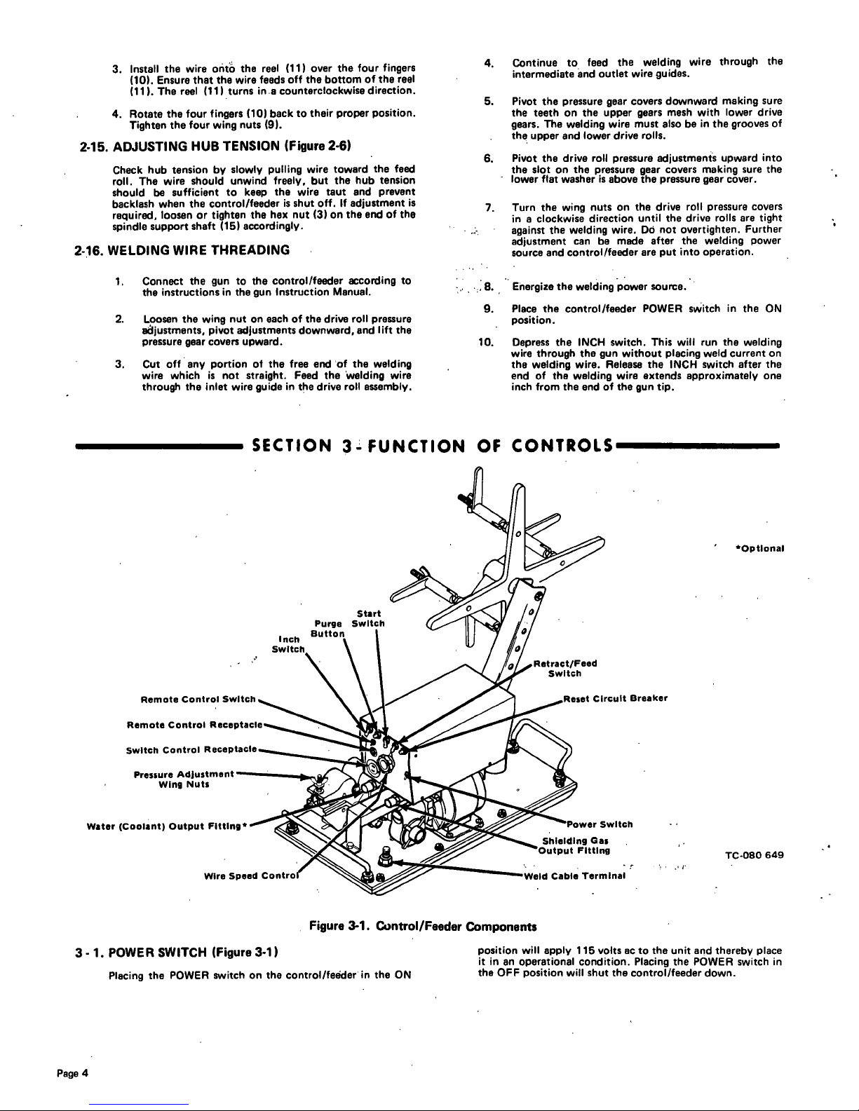
3-1.
POWER
SWITCH
(Figure
3-1)
SECTION
3.~.FUNCTION
OF
CONTROLS
Figure
3-1.
Control/Feeder
Components
Placing
the
POWER
switch
on
the
control/feeder
in
the
ON
TC-080
649
position
will
apply
115
volts
ac
to
the
unit
and
thereby
place
it
in
an
operational
condition.
Placing
the
POWER
switch
in
the
OFF
position
will
shut
the
control/feeder
down.
Start
Optlonal
Water
(Coolant)
Output
Flttlng*
Wire
Speed
Cou
Circuit
Breaker
Switch
Cable
Terminal
V
Page
4
3-4.
PURGE
BUTTON
(Figure
3-1)
I
Placing
the
POWER
switch
in
the
C
~ition
does
not
remove
power
from
all
of
the
control/feeders
internal
circuitry.
Completely
terminate
all
electrical
power
to
the
control/feeder
by removing
the
115
volts
ac
plug
from
its
power
supply,
and
ensure
that
machinery
lockout
procedures
have
been
employed
on
the
welding
power
sources
input
line
(see
Instruc
tion
Manual
on
welding
power
source)
before
attempt-
ing
any
inspection
or
work
inside
the
unit
3-
2.
WIRE
SPEED
CONTROL
(Figure
3-1)
The
WIRE
SPEED
control
provides
a
means
of
determining
the
rate
at
which
welding
wire
will
be
fed
into
the
weld.
Rotating
the
WIRE
SPEED
control
in
a
clockwise
direction
will
increase
the
rate
of
the
wire
feed.
When
the
WIRE
SPEED
control
is
set
at
0,
wire
will
feed
at
the
slowest
speed;
when
set
at
100,
the
wire
will
feed
at
the
fastest
speed.
The
scale
which
surrounds
the
WIRE
SPEED
control
is
calibrated
in
increments
of
ten
ranging
from
0
to
100
percent.
Due
to
this
percentage
calibration,
it
should
be
noted
that
if
this
scale
is
being
usedtoselect
a
wire
feed
speed
setting,
only
a
percentage
of
the
range
in
use
is
being
selected
and
not
an
actual
wire
feed
speed
rate.
3-3.
REMOTE
CONTROL
RECEPTACLE
&
SWITCH
(Figure
3-1)
The
wire
speed
may
also
be
adjusted
by
a
Remote
Control
(optional).
Connect
the
Remote
Control
plug
to
the
REMOTE
CONTROL
receptacle
on
the
front
panel
of
the
control/feeder,
and
position
the
REMOTE
CONTROL
switch
on
the
control/feeder
and
on
the
Remote
Control
unittothe
REMOTE
position.
If
it
is
desired
to
return
the
control
of
the
wire
speed
to
the
control/feeder,
place
the
REMOTE
CONTROL
switch
on
either
the
control/feeder
or
the
Remote
Control
to
the
STANDARD
position.
The
PURGE
button,
located
on
the
front
panel
of
the
control/feeder,
is
a
momentary
contact
switch.
This
switch
will
energize
the
gas
solenoid
and
purge
the
shielding
gas
line
of
the
gun.
The
PURGE
button
also
allows
the
shielding
gas
regulator
to
be
adjusted
without
energizing
the
welding
circuit.
3
-
5.
INCH
SWITCH
(Figure
3-1)
The
INCH
switch,
located
on
the
front
panel
of
the
control/feeder,
is
a
spring-loaded
toggle
switch.
When
actuated
it
completes
the
circuittothe
motor
without
having
to
depress
the
gun
trigger
switch.
This
switch
will
permit
inching
of
the
wire
at
whatever
setting
the
WIRE
SPEED
control
is
at,
without
energizing
the
welding
cirucit
or
the
shielding
gas
valve.
3-
6.
START
SWITCH
(Figure
3-1)
The
START
switch
provides
the
capability
of
being
able
to
select
either
a
slow
wire
feed
speed
for
1/2
second
at
the
beginning
of
wire
feed,
or
the
wire
feed
speed
at
the
rate
set
on
the
WIRE
SPEED
control.
The
SLOW
position
of
the
START
switch
will
provide
the
1/2
second
of
slow
wire
feed,
and
the
FAST
position
will
provide
wire
feed
at
the
rate
set
on
the
WIRE
SPEED
control.
3-7.RETRACT-FEED
SWITCH
(Figure
3-1)
The
RETRACT-FEED
switch
will
determine
whether
the
wire
will
feed
out
of
the
gun
or
back
into
the
gun
when
the
gun
switchisclosed.
The
RETRACT
position
will
cause
the
wire
to
go
back
into
the
gun,
and
the
FEED
position
will
cause
the
wire
to
feed
out
of
the
gun.
3-8.
RESET
CIRCUIT
BREAKER
(Figure
3-1)
A
circuit
breaker,
located
on
the
upper
portion
of
the
control/feeder
front
panel,
provides
protection
to
the
con
trol/feeder
motor.
In
the
event
the
motor
should
be
placed
in
an
overload
condition,
the
breaker
would
trip
and
suspend
elI
output.
Should
this
breaker
trip,
the
RESET
button
would
have
to
be
manually
depressed
to
reset
the
circuit
breaker.
1.
Make
all
connections
as
instructed
in
Section
2.
2.
Place
the
RETRACT-FEED
switch
in
the
FEED
position.
3.
Place
the
START
switch
in
the
desired
position.
4.
Rotate
the
WIRE
SPEED
control
to
the
desired
setting.
5.
If
a
Remote
Wire
Speed
Control
is
not
to
be
used,
place
the
REMOTE
CONTROL
switch
in
the
STANDARD
position.
IfaRemote
Wire
Speed
Con
trol
is
to
be
used,
place
both
the
REMOTE
CONTROL
switch
on
the
Remote
Wire
Speed
Control
and
on
the
control/feeder
in
the
REMOTE
position.
to
welding,
it
is
impera!
that
p
roper
p
ro
tect
ive
clothing
(welding
coat
and
gloves)
and
eye
protection
(glasses
and/or
welding
helmet)
be
put
on.
Failure
to
comply
may
result
in
serious
or
permanent
bodily
damage.
6.
Place
the
POWER
switch
on
the
control/feeder
in
the
ON
position.
7.
Depress
the
PURGE
button
for
one
minute.
8.
Energize
the
welding
power
source.
9.
Hold
the
tip
of
the
gun
approximately
1/2
inch
from~
the
workpiece.
10.
Depress
the
trigger
on
the
gun
handle.
Gas
and
water
will
start
to
flow,
and
wire
will
start
to
feed
if
drive
roll
pressure
is
properly
adjusted
to
prevent
slippage.
If
wire
slippage
is
noticed,
tighten
the
drive
roll
pressure
adjustment
wing
nuts
1/2
turn
clockwise.
Repeat
until
slippage
stops.
Do
not
tighten
wing
nuts
too
much.
CAUTION
The
welding
wire
and
all
metal
parts
in
contact
with
it
are
energized
while
welding.
Do
not
touch
the
welding
wire
or
any
metal
part
making
contact
with
it.
4-2.
SHUTTING
DOWN
1.
Turn
off
the
shielding
gas
and
water
at
the
source.
2.
Place
the
POWER
switch
on
the
control/feeder
in
the
OFF
position,
and
remove
the
115
Volts
AC
plug
from
the
source.
3.
Turn
off
all
associated
equipment.
~ding
is
performed
in
a
confined~
failure
to
turn
off
the
shielding
gas
supply
could
result
in
a
buildup
of
gas
fumes,
thereby
endangering
personnel
reentering
the
welding
area.
I
SECTION
4
-
SEQUENCE
OF
OPERATION
4-
1.
GAS
METAL-ARC
WELDING
(GMAW)
I
OM-t234Page5
 Loading...