

Miller Electric Millermatic 155, M-15 Owner's Manual
June 1996 Form: OM-1314
And Dia
Effective With Serial No. KG171523
OWNER’S
MANUAL
Millermatic® 155 And M-15 Gun
Rated Welding
Output
130 A @ 20.5 Volts
DC, 30% Duty Cycle
Wire Type
* While idling
cover_om 4/95 − ST-800 091-C PRINTED IN USA
Amperage
Range
40 − 170
Solid/
Stainless
.023 − .035 in
(0.6 − 0.9 mm)
230 Volt Wire Welder
Maximum
Open-Circuit
Voltage DC
33
Flux Cored/
Aluminum
.030 − .045 in
(0.8 − 1.1 mm)
© 1996 MILLER Electric Mfg. Co.
Amperes Input at
Rated Load Output 115 V, 60 Hz,
Single-Phase
20.5
(0.27)*
Calculated Wire
Speed Range At
No Load
126 − 722 IPM
(3.2 − 18.3 m/min)
KVA KW Weight
4.7
(.05)*4(.04)*
Max Wire Feed Speed While Welding
80 lb
(36.3 kg)
500 IPM
(12.7 m/min)
Overall
Dimensions
Length: 17 in
(432 mm)
Width: 10 in
(254 mm)
Height: 15-1/2 in
(394 mm)
SECTION 1 − INSTALLATION
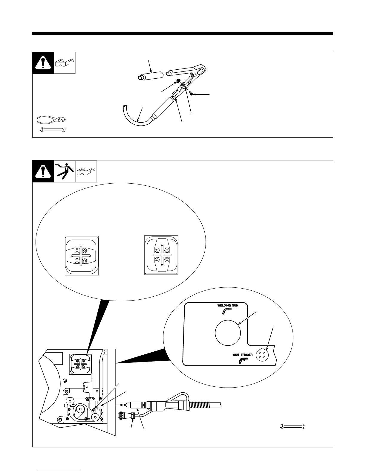
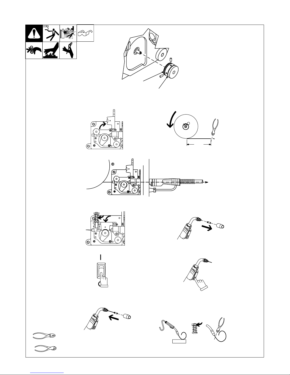
1-1. Installing Work Clamp
Tools Needed:
3/8, 7/16 in
1
6
5
3
4
2
1 Insulator
2 Bolt
3 Smaller Hole
4 Work Clamp Tabs
Bend tabs around work cable.
5 Work Cable From Unit
6 Nut
1-2. Installing Welding Gun And Setting Gun Polarity For Wire Type
1 Gun Opening
2 Gun Trigger Receptacle
3 Gun Securing Nut
4 Drive Assembly
5 Gun End
. Follow wire manufacturer’s recommendation.
Flux Cored Wires
(FCAW−Without Gas)
Aluminum Wires
(GMAW−With Gas)
Solid Steel Or
Loosen securing nut. Insert gun
end through opening until it bottoms
against drive assembly. Tighten
nut.
6 Gun Trigger Plug
Insert plug into receptacle, and
tighten threaded collar.
Close door.
Ref. ST-025 190-D
Straight Polarity
DCEN
Reverse Polarity
DCEP
1
2
Front Panel Openings
3
4
Tools Needed:
56
ST-149 328-B / Ref. ST-159 270
5/16 in
OM-1314 Page 5
1-3. Electrical Service Guide
Input Voltage
Input Amperes At Rated Output
Max Recommended Standard Fuse Or Circuit Breaker Rating In Amperes
Min Input Conductor Size In AWG/Kcmil
Max Recommended Input Conductor Length In Feet (Meters)
Min Grounding Conductor Size In AWG/Kcmil
Reference: 1996 National Electrical Code (NEC) S-0092-J
230
20.5
25
14
64 (19)
14
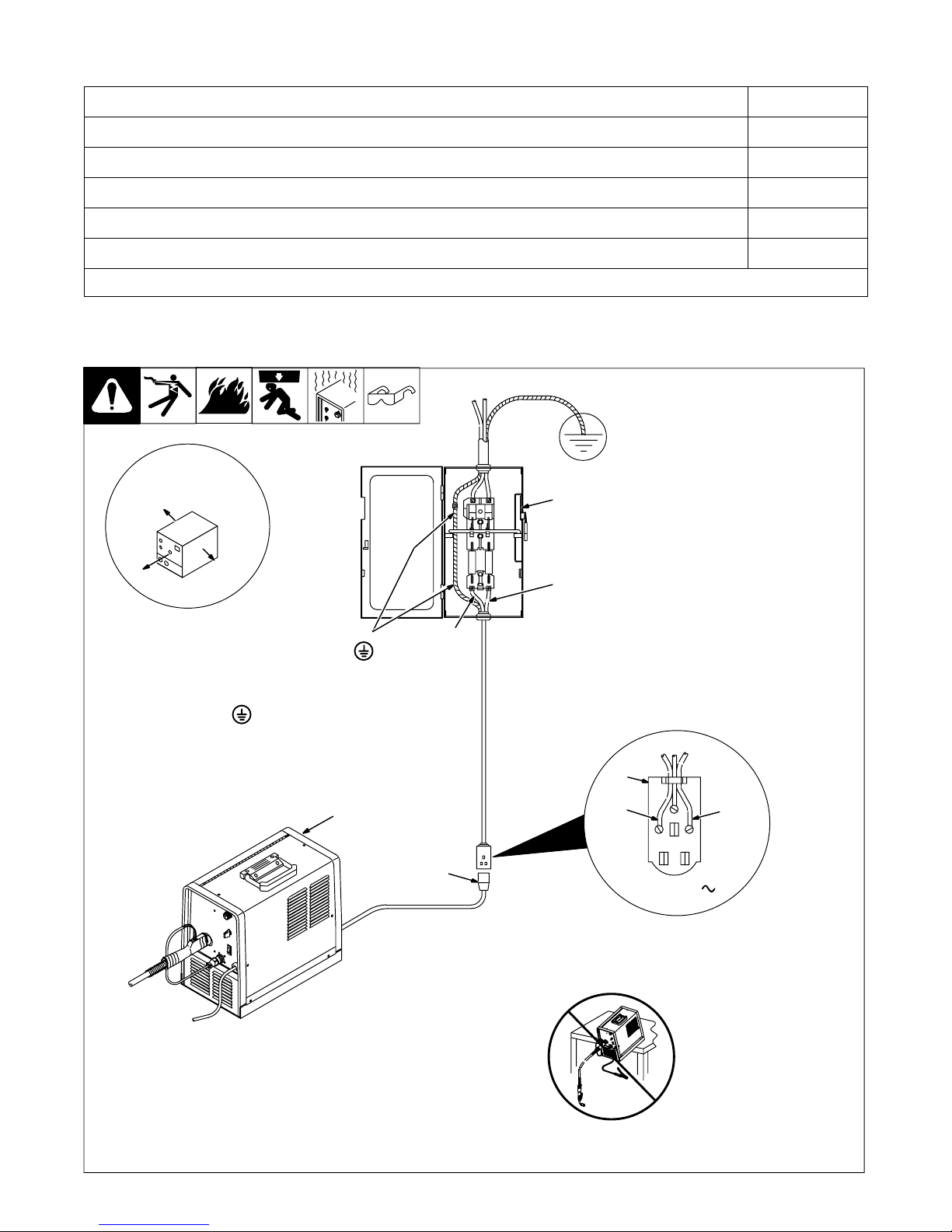
1-4. Selecting A Location And Connecting Input Power
1 Rating Label
Supply correct input power.
2 Plug
3 Receptacle
Connect plug to receptacle.
18 in (457 mm) of
space for airflow
4
L1
4 Line Disconnect Device
See Section 1-3.
Y Special installation may be
required where gasoline or
volatile liquids are present −
see NEC Article 511 or CEC
Section 20.
Y Always connect
grounding
conductor first.
= GND/PE
L2
1
2
Y Do not move or operate unit
where it could tip.
3
L2
L1
230 VAC, 1
OM-1314 Page 6
ssb2.2* 1/94 − ST-801 504

1-5. Installing Wire Spool And Adjusting Hub Tension
Standard Wire Spool
Tools Needed:
1 Lb Wire Spool
When a slight force is needed
to turn spool, tension is set.
15/16 in
S-0499
OM-1314 Page 7
1-6. Installing Drive Roll And Threading Welding Wire
1 Install drive roll.
For Flux Cored Wire
For Solid Wire
Install drive roll onto shaft with desired groove in, and one set screw
facing flat side of shaft. Tighten both
set screws.
2 Open pressure assembly.
4 Push wire thru guides into gun;
continue to hold wire.
5 Close and tighten pressure assembly,
and let go of wire.
3 Pull and hold wire; cut off end.
6 in
(150 mm)
6 Remove gun nozzle and contact tip.
7 Turn power On.
9 Reinstall contact tip and nozzle.
Tools Needed:
OM-1314 Page 8
8 Press gun trigger until wire comes out
of gun.
10 Feed wire to check drive roll
pressure. Tighten knob enough to
prevent slipping. Cut off wire; leave
1/4−1/2 in (6−13 mm). Close and
latch door.
WOOD
Ref. ST-149 266-B / Ref. ST-149 326-B / Ref. 150 093-A / Ref. 180 968 / S-0627-A
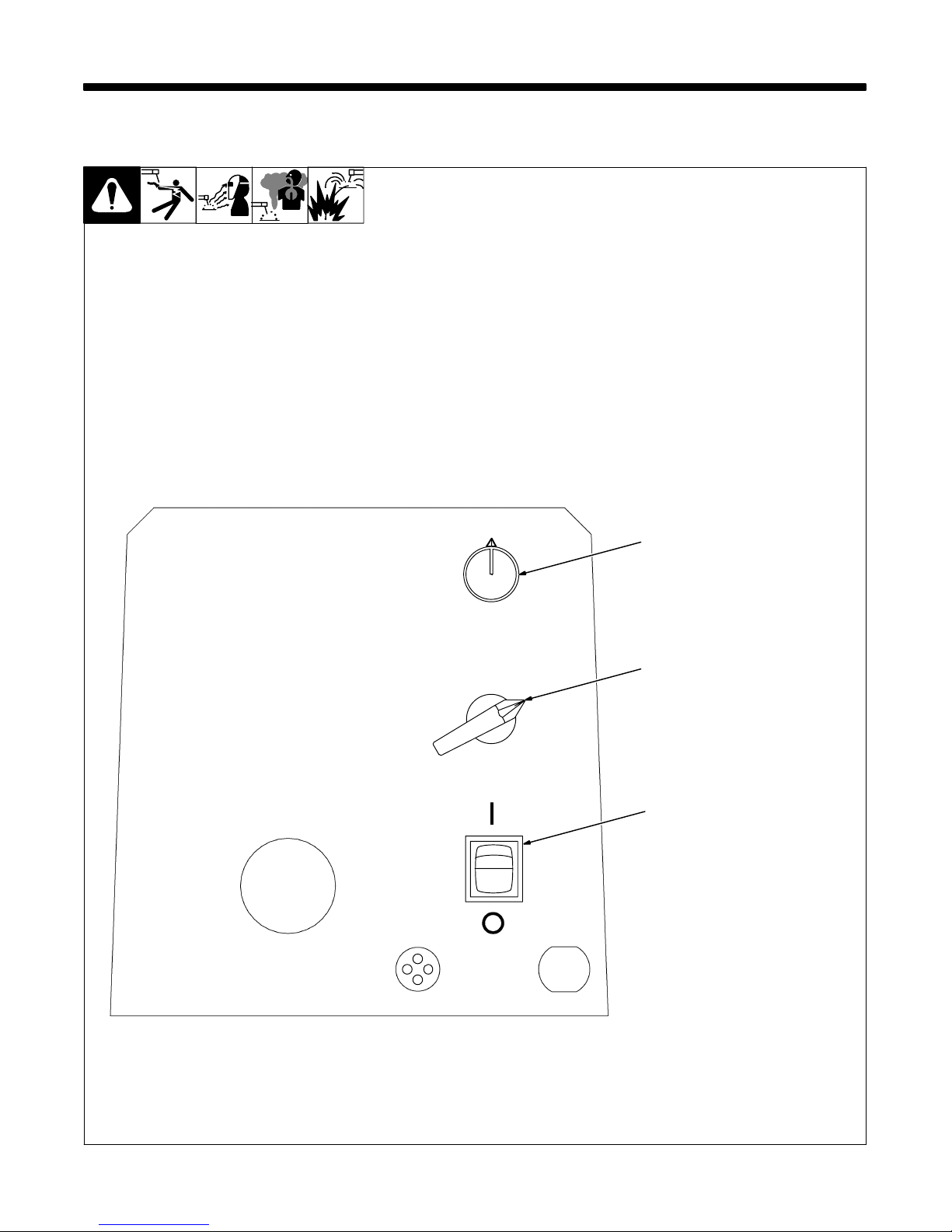
2-1. Controls
SECTION 2 − OPERATION
1 Wire Speed Control
Use control to select a wire feed
speed. As Voltage switch setting increases, wire speed range also increases.
2 Voltage Switch
The higher the selected number,
the thicker the material that can be
welded. Do not switch while
welding.
3 Power Switch
1
2
3
Ref. ST-180 968
OM-1314 Page 9

NOTES
OM-1314 Page 10
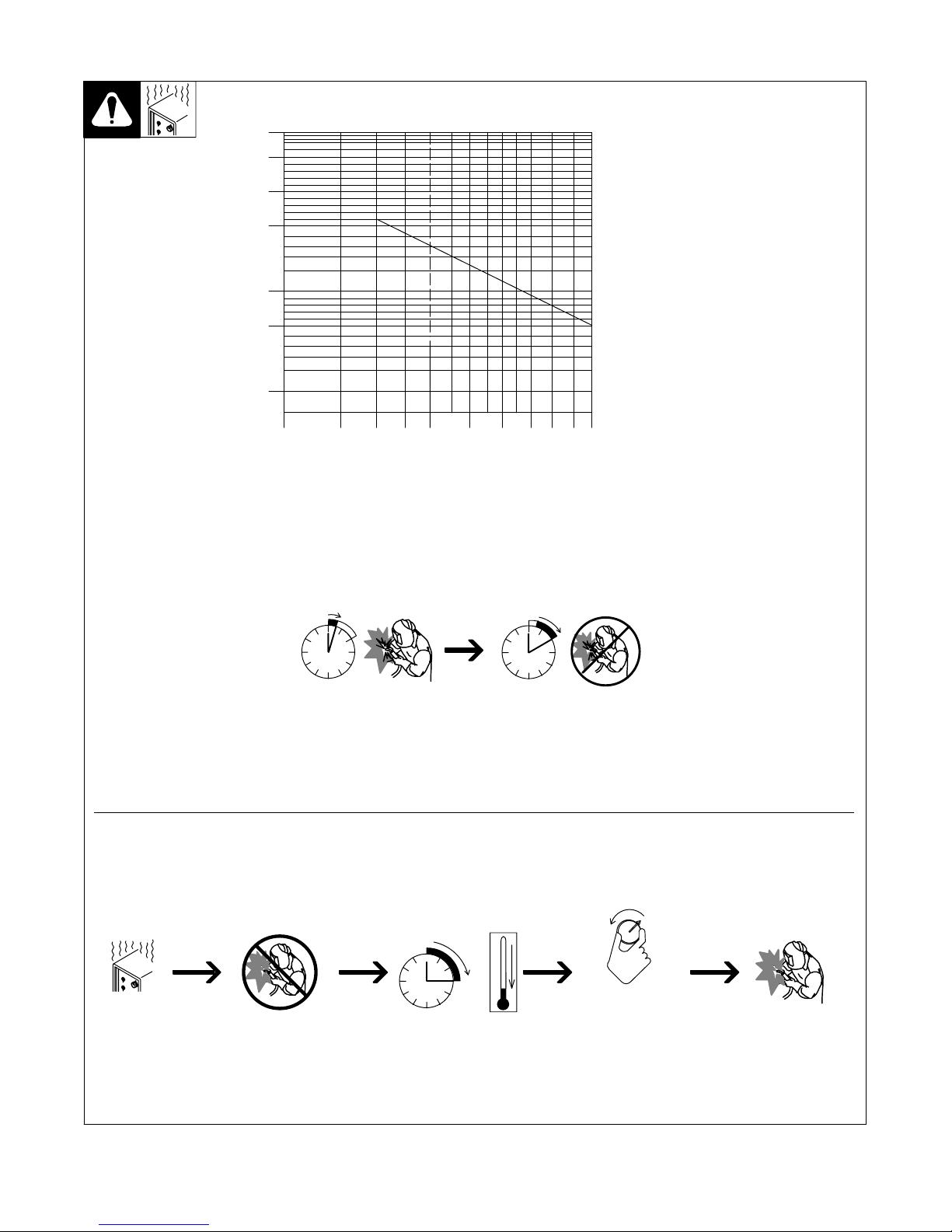
2-2. Duty Cycle And Overheating
300
250
200
150
100
DC AMPERES
75
50
10 15 20 25 30 40 50 60 70 80 100
Duty Cycle is percentage of 10 minutes that unit can weld at rated load
without overheating.
If unit overheats, thermostat(s)
opens, output stops, and cooling
fan runs. Wait fifteen minutes for
unit to cool. Reduce amperage or
duty cycle before welding.
Y Exceeding duty cycle can
damage unit or gun and void
warranty.
% DUTY CYCLE
Overheating
30% Duty Cycle At 130 Amperes
3 Minutes Welding 7 Minutes Resting
0
15
Reduce Duty Cycle
Minutes
A or V
OR
duty1 4/95 − SB-180 844
OM-1314 Page 11
 Loading...