

Miller Electric Legend AEAD-200LE Technical Manual
February 1996 Form: TM-428
Effective With Serial No. JH242114
TECHNICAL MANUAL
Service And Parts
cover_tm 4/95 – ST-140 091-E PRINTED IN USA
1996 MILLER Electric Mfg. Co.
Miller Legend
(Formerly The Legend AEAD-200LE)
CC AC/DC Welding Generator For SMAW, GMAW, GTAW Welding
Welding
Mode
Weld
Output
Range
Rated
Welding
Output
Maximum
Open-Circu
it Voltage
Auxiliary Power
Rating
Fuel Capacity Engine
CC/AC 35
– 225 A
225 A, 25 V
,
100% Duty
Cycle
80
Single-Phase,
5 kVA/kW
, 42/21 A,
120/240 V AC, 60 Hz
Onan P218 Air-Cooled,
-
-
CC/DC
25 – 200 A
200 A, 25 V
,
100% Duty
Cycle
72
And
Single-Phase,
1 kVA/kW
, 9 A,
1
15 V AC, 100 Hz
7.5 gal (28 L) T
ank
T
wo-Cylinder, Four-Cycle,
Gasoline Engine

OM-428N 1/96 – SPM-428C 6/94
H CALL:
Miller Customer Service
Department at
414-735-4505
WHO DO I CONTACT FOR HELP?
H FAX:
800-637-2348
(in USA),
or
414-735-4136 (outside USA)
H WRITE:
Miller Electric Mfg. Co.
P
.O. Box 1079
Appleton, WI 54912 USA
Always provide Model Name and Serial or Style Number
TABLE OF CONTENTS
SECTION 1 – SAFETY PRECAUTIONS FOR SERVICING 1.
. . . . . . . . . . . . . . . . . . . . . . . . . . . . . . . . . . .
1-1. Symbol Usage 1.
. . . . . . . . . . . . . . . . . . . . . . . . . . . . . . . . . . . . . . . . . . . . . . . . . . . . . . . . . . . . . . . .
1-2. Servicing Hazards 1.
. . . . . . . . . . . . . . . . . . . . . . . . . . . . . . . . . . . . . . . . . . . . . . . . . . . . . . . . . . . . .
1-3. EMF Information 2.
. . . . . . . . . . . . . . . . . . . . . . . . . . . . . . . . . . . . . . . . . . . . . . . . . . . . . . . . . . . . . .
SECTION 2 – INSTALLATION 3.
. . . . . . . . . . . . . . . . . . . . . . . . . . . . . . . . . . . . . . . . . . . . . . . . . . . . . . . . . . . .
2-1. Installing Welding Generator 3.
. . . . . . . . . . . . . . . . . . . . . . . . . . . . . . . . . . . . . . . . . . . . . . . . . . . .
2-2. Dimensions, Weights, And Operating Angles 3.
. . . . . . . . . . . . . . . . . . . . . . . . . . . . . . . . . . . . . .
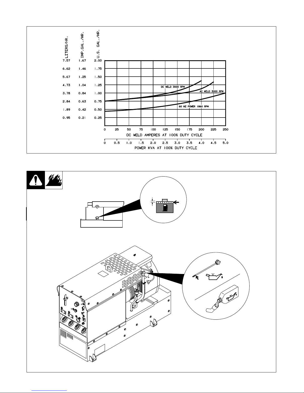
2-3. Fuel Consumption 4.
. . . . . . . . . . . . . . . . . . . . . . . . . . . . . . . . . . . . . . . . . . . . . . . . . . . . . . . . . . . . .
2-4. Engine Prestart Checks 4.
. . . . . . . . . . . . . . . . . . . . . . . . . . . . . . . . . . . . . . . . . . . . . . . . . . . . . . . .
2-5. Connecting The Battery 5.
. . . . . . . . . . . . . . . . . . . . . . . . . . . . . . . . . . . . . . . . . . . . . . . . . . . . . . . .
2-6. Connecting To Weld Output Terminals 5.
. . . . . . . . . . . . . . . . . . . . . . . . . . . . . . . . . . . . . . . . . . . .
2-7. Selecting Weld Cable Sizes 6.
. . . . . . . . . . . . . . . . . . . . . . . . . . . . . . . . . . . . . . . . . . . . . . . . . . . . .
2-8. Remote 14 Receptacle RC1 Information 6.
. . . . . . . . . . . . . . . . . . . . . . . . . . . . . . . . . . . . . . . . . .
SECTION
3 – OPERA
TING WELDING GENERATOR 7.
. . . . . . . . . . . . . . . . . . . . . . . . . . . . . . . . . . . . . . . .
3-1. Front Panel Controls 7.
. . . . . . . . . . . . . . . . . . . . . . . . . . . . . . . . . . . . . . . . . . . . . . . . . . . . . . . . . . .
3-2. Remote Control (Optional) 8.
. . . . . . . . . . . . . . . . . . . . . . . . . . . . . . . . . . . . . . . . . . . . . . . . . . . . . .
3-3. Duty Cycle 8.
. . . . . . . . . . . . . . . . . . . . . . . . . . . . . . . . . . . . . . . . . . . . . . . . . . . . . . . . . . . . . . . . . . . .
3-4. Volt-Ampere Curves 9.
. . . . . . . . . . . . . . . . . . . . . . . . . . . . . . . . . . . . . . . . . . . . . . . . . . . . . . . . . . .
SECTION
4 – OPERA
TING AUXILIAR
Y EQUIPMENT
10.
. . . . . . . . . . . . . . . . . . . . . . . . . . . . . . . . . . . . . . .
4-1. 100 Hz Auxiliary Power Receptacle And Circuit Breaker 10.
. . . . . . . . . . . . . . . . . . . . . . . . . . . .
4-2. AC Auxiliary Power Curve 10.
. . . . . . . . . . . . . . . . . . . . . . . . . . . . . . . . . . . . . . . . . . . . . . . . . . . . . .
4-3. 60 Hz Auxiliary Power Receptacles And Circuit Breakers 11.
. . . . . . . . . . . . . . . . . . . . . . . . . . .
SECTION 5 – THEOR
Y OF OPERA
TION 12.
. . . . . . . . . . . . . . . . . . . . . . . . . . . . . . . . . . . . . . . . . . . . . . . . . . .
SECTION 6 – TROUBLESHOOTING 15.
. . . . . . . . . . . . . . . . . . . . . . . . . . . . . . . . . . . . . . . . . . . . . . . . . . . . . .
6-1. Troubleshooting Tables 15.
. . . . . . . . . . . . . . . . . . . . . . . . . . . . . . . . . . . . . . . . . . . . . . . . . . . . . . . . .
6-2. Troubleshooting Circuit Diagram For Welding Generator 18.
. . . . . . . . . . . . . . . . . . . . . . . . . . . .
6-3. Troubleshooting Circuit Diagram For Welding Generator With Optional Remote Control 20.
.
6-4. Waveforms For Sections 6-2 And 6-3 22.
. . . . . . . . . . . . . . . . . . . . . . . . . . . . . . . . . . . . . . . . . . . .
6-5. Idle Control Board/Module PC1 Testing Information 23.
. . . . . . . . . . . . . . . . . . . . . . . . . . . . . . . .
6-6. Troubleshooting Flowcharts For Idle Control Board/Module PC1 24.
. . . . . . . . . . . . . . . . . . . . .
6-7. Voltage Regulator Board PC2 Testing Information Prior To Serial No. KE604176 26.
. . . . . . .
6-8. Voltage Regulator Board PC2 Test Point Values Prior To Serial No. KE604176 26.
. . . . . . . .
6-9. Voltage Regulator Board PC2 Testing Information Effective With Serial No. KE604176 27.
. .
6-10. Voltage Regulator Board PC2 Test Point Values Effective With Serial No. KE604176 27.
. . .
6-11. Optional Remote Control Board PC3 Testing Information 28.
. . . . . . . . . . . . . . . . . . . . . . . . . . .
6-12. Optional Remote Control Board PC3 Test Point Values 28.
. . . . . . . . . . . . . . . . . . . . . . . . . . . . .
6-13. Optional Remote Capacitor Board PC5 Testing Information Effective With
Serial No. KD346698 29.
. . . . . . . . . . . . . . . . . . . . . . . . . . . . . . . . . . . . . . . . . . . . . . . . . . . . . . . . . .
6-14. Optional Remote Capacitor Board PC5 Test Point Values Effective With
Serial No. KD346698 29.
. . . . . . . . . . . . . . . . . . . . . . . . . . . . . . . . . . . . . . . . . . . . . . . . . . . . . . . . . .
6-15. Replacing Brushes And Cleaning Slip Rings 30.
. . . . . . . . . . . . . . . . . . . . . . . . . . . . . . . . . . . . . .
6-16. Checking Unit Output After Servicing 32.
. . . . . . . . . . . . . . . . . . . . . . . . . . . . . . . . . . . . . . . . . . . . .

SECTION 7 – DISASSEMBL
Y AND REASSEMBL
Y 33.
. . . . . . . . . . . . . . . . . . . . . . . . . . . . . . . . . . . . . . . . .
7-1. Disassembly Of Unit 33.
. . . . . . . . . . . . . . . . . . . . . . . . . . . . . . . . . . . . . . . . . . . . . . . . . . . . . . . . . . .
7-2. Disassembly Of Generator 34.
. . . . . . . . . . . . . . . . . . . . . . . . . . . . . . . . . . . . . . . . . . . . . . . . . . . . . .
SECTION 8 – MAINTENANCE 35.
. . . . . . . . . . . . . . . . . . . . . . . . . . . . . . . . . . . . . . . . . . . . . . . . . . . . . . . . . . . .
8-1. Routine Maintenance 35.
. . . . . . . . . . . . . . . . . . . . . . . . . . . . . . . . . . . . . . . . . . . . . . . . . . . . . . . . . .
8-2. Maintenance Label 36.
. . . . . . . . . . . . . . . . . . . . . . . . . . . . . . . . . . . . . . . . . . . . . . . . . . . . . . . . . . . .
8-3. Servicing Air Cleaner 37.
. . . . . . . . . . . . . . . . . . . . . . . . . . . . . . . . . . . . . . . . . . . . . . . . . . . . . . . . . .
8-4. Changing Engine Oil, Oil Filter, And Fuel Filter 38.
. . . . . . . . . . . . . . . . . . . . . . . . . . . . . . . . . . . .
8-5. Adjusting Engine Speed 39.
. . . . . . . . . . . . . . . . . . . . . . . . . . . . . . . . . . . . . . . . . . . . . . . . . . . . . . . .
8-6. Overload Protection 40.
. . . . . . . . . . . . . . . . . . . . . . . . . . . . . . . . . . . . . . . . . . . . . . . . . . . . . . . . . . . .
8-7. Inspecting And Cleaning Optional Spark Arrestor 40.
. . . . . . . . . . . . . . . . . . . . . . . . . . . . . . . . . .
SECTION 9 – ELECTRICAL DIAGRAMS 41.
. . . . . . . . . . . . . . . . . . . . . . . . . . . . . . . . . . . . . . . . . . . . . . . . . .
SECTION 10 – PARTS LIST 51.
. . . . . . . . . . . . . . . . . . . . . . . . . . . . . . . . . . . . . . . . . . . . . . . . . . . . . . . . . . . . . .

TM-428 Page 1
Miller Legend
SECTION 1 – SAFETY PRECAUTIONS FOR SERVICING
safety_rtm1 4/95
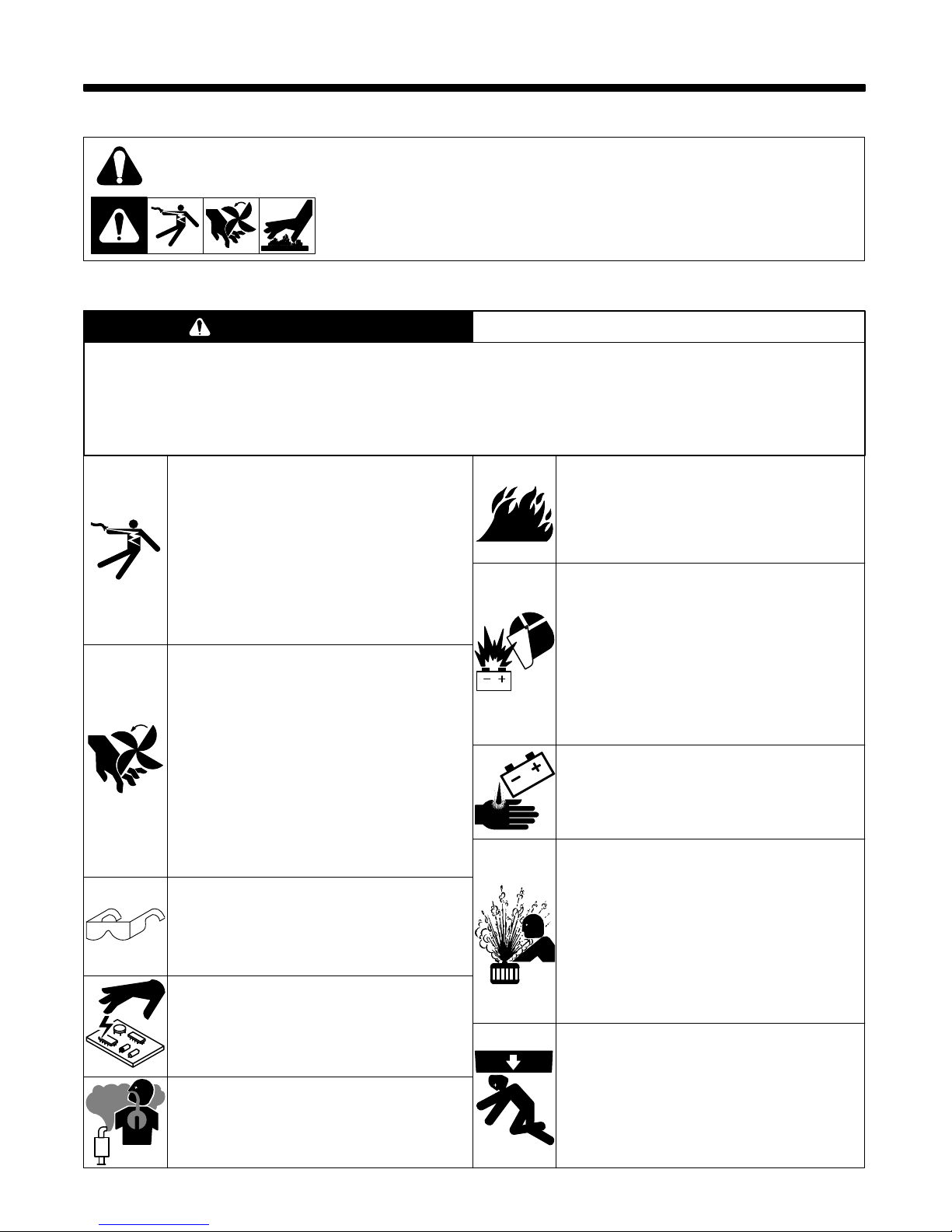
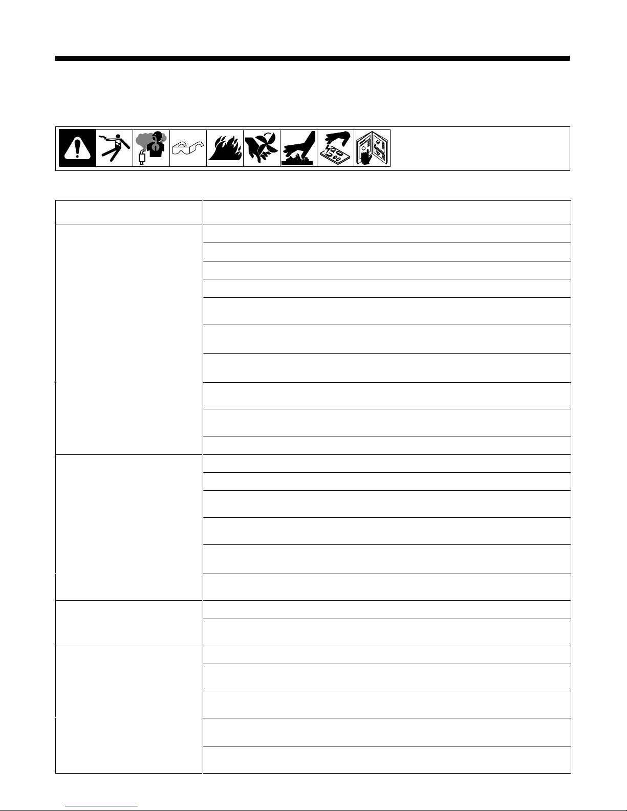
1-1. Symbol Usage
Means Warning! Watch Out! There are possible hazards with this
procedure!
The possible hazards are shown in the adjoining symbols.
This group of symbols means Warning! Watch Out! possible ELECTRIC SHOCK, MOVING
PARTS,
and HOT PARTS hazards. Consult symbols and related instructions below for necessary
actions
to avoid the hazards.
Y
Marks a special safety message.
.
Means NOTE; not safety related.
1-2. Servicing Hazards
ELECTRIC SHOCK can kill.
1. Do
not touch live electrical parts.
2. Stop
engine before testing or repairing unit unless
the procedure specifically requires an energized
unit.
3. Insulate yourself from ground by standing or
working on dry insulating mats big enough to
prevent
contact with the ground.
4.
Do not leave live unit unattended.
5. When
testing live unit, use
the one-hand method.
Do not put both hand inside unit. Keep one
hand
free.
MOVING PARTS can cause injury.
1. Keep
away from moving
parts such as fans, belts,
and
rotors.
2. Have only qualified people remove guards or
covers for maintenance and troubleshooting as
necessary.
3. Keep hands, hair, loose clothing, and tools away
from
moving parts.
4. Before
working on generator
, remove spark plugs
or injectors to keep engine from kicking back or
starting.
5. Block
flywheel so that it will not
turn while working
on
generator components.
6.
Reinstall panels or
guards and close doors when
servicing is finished and before starting engine.
FLYING
PIECES
OF MET
AL or DIRT can
cause injury.
1. Always wear safety glasses with side shields or
face
shield during servicing.
2. Be
careful not to short metal tools, parts, or wires
together
during testing and servicing.
STATIC
ELECTRICITY
can damage parts
on circuit boards.
1. Put on grounded wrist strap BEFORE handling
boards
or parts.
2. Use proper static-proof bags to store, move, or
ship
PC boards.
ENGINE EXHAUST GASES can kill.
1. Do
not breathe exhaust fumes.
2. Use in open, well-ventilated areas, or vent
exhaust outside and away from any building air
intakes.
ENGINE FUEL can cause fire or
explosion.
1. Stop
engine before fueling.
2. Do not fuel while smoking or near sparks or
flames.
3. Do
not overfill tank; clean up any spilled fuel.
BATTERY EXPLOSION can BLIND and
INJURE.
1. Always wear a face shield when working on a
battery.
2. Stop engine before disconnecting or connecting
battery
cables.
3. Do
not allow tools to cause sparks when working
on a battery
.
4. Do
not use welder to charge batteries or jump
start
vehicles.
5. Observe
correct polarity (+ and –) on batteries.
BATTERY ACID can BURN SKIN.
1. Do
not tip.
2.
Replace damaged battery
.
3.
Flush eyes and skin immediately with water
.
STEAM AND PRESSURIZED HOT
COOLANT can burn face, eyes, and
skin.
1. Check coolant level when
engine is cold to avoid
scalding.
2. If the engine is warm and checking is needed,
follow
steps 3 and 4.
3. Wear
safety glasses and gloves and put a rag over
cap.
4. Turn cap slightly and let pressure escape slowly
before
completely removing cap.
FALLING EQUIPMENT can cause
serious personal injury and equipment
damage.
1. Use equipment of adequate capacity to lift
components.
2. Use
a lifting eye to lift unit only, NOT running gear
,
gas cylinders, or any other accessories.
3.
Securely attach components to lifting
equipment.
The symbols shown below are used throughout this manual to call attention to and identify possible
hazards. When you see the symbol, watch out, and follow the related instructions to avoid the hazard.
Only qualified persons should service, test, maintain, and repair this unit.
During servicing, keep everybody, especially children, away.
WARNING
TM-428 Page 2
Miller Legend
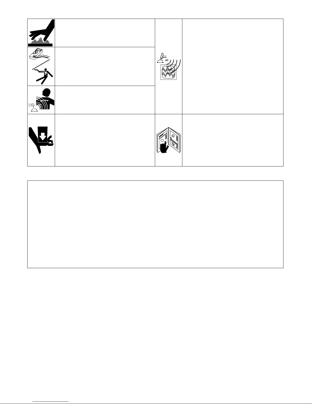
HOT PARTS can cause severe burns.
1. Allow
cooling period before servicing.
2. Wear
protective gloves and clothing when working
on
a hot engine.
ELECTRIC SHOCK HAZARD from
incorrect use of test equipment.
1. Stop engine before making or changing meter
lead
connections.
2. At
least one meter lead should be a self-retaining
spring
clip such as an alligator clamp.
3.
Read instructions for test equipment.
MAGNETIC FIELDS FROM HIGH
CURRENTS can affect pacemaker
operation.
1. Pacemaker wearers keep away from servicing
areas
until consulting your doctor
.
UNCONTROLLED TILTING OR TIPPING
OF UNIT can result in personal injury
and equipment damage.
1. Do
not put any body part under unit while lifting.
2. Use adequate blocks to support components as
needed
during job.
PINCH POINTS can injure.
1. Be careful when working on stator and rotor
assemblies.
HIGH-FREQUENCY RADIATION can
interfere with radio navigation, safety
services, computers, and
communications equipment.
1. Have only qualified persons familiar with
electronic
equipment perform this installation.
2. The user is responsible for having a qualified
electrician promptly correct any interference
problem
resulting from the installation.
3. If notified by the FCC about interference, stop
using
the equipment at once.
4. Have the installation regularly checked and
maintained.
5. Keep high-frequency source doors and panels
tightly shut, keep spark gaps at correct setting,
and use grounding and shielding to minimize the
possibility
of interference.
READ INSTRUCTIONS.
1. Use MILLER Testing Booklet (Part No. 150 853)
when
servicing this unit.
2. Consult the Owner’s Manual for welding safety
precautions.
3. Use
only genuine MILLER replacement parts.
4. Reinstall injectors and bleed air from fuel system
according to engine manual.
1-3. EMF Information
Considerations
About W
elding And The Ef
fects Of Low
Frequency
Electric
And Magnetic Fields
The
following is a quotation from the
General Conclusions Section
of
the U.S. Congress, Of
fice of T
echnology Assessment,
Biological
Effects of Power Frequency Electric & Magnetic Fields –
Background Paper
, OTA-BP-E-53 (Washington, DC: U.S.
Government Printing Office, May 1989): “. . . there is now a very
large volume of scientific findings based on experiments at the
cellular
level and from studies with
animals and people which clearly
establish that low frequency magnetic fields can interact with, and
produce
changes in, biological systems.
While most of this work is of
very high quality, the results are complex. Current scientific
understanding does not yet allow us to interpret the evidence in a
single coherent framework. Even more frustrating, it does not yet
allow us to draw definite conclusions about questions of possible
risk
or to of
fer clear science-based advice on strategies to minimize
or
avoid potential risks.”
To reduce magnetic fields in the workplace, use the following
procedures:
1. Keep
cables close together by twisting or taping them.
2.
Arrange cables to one side and away from the operator
.
3.
Do not coil or drape cables around the body
.
4.
Keep welding power source and cables as far away as
practical.
5.
Connect work clamp to workpiece as close to the weld as
possible.
About Pacemakers:
The above procedures are also recommended for pacemaker
wearers.
Consult your doctor for complete information.
TM-428 Page 3
Miller Legend
SECTION 2 – INSTALLATION
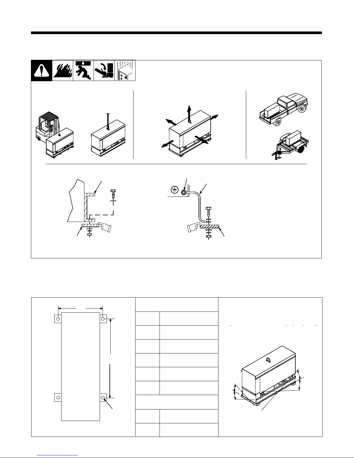
2-1. Installing Welding Generator
install1 10/95 – Ref. ST-800 652 / Ref. ST-800 477-A / ST-158 936-A / S-0854
1
2
Electrically
bond
generator frame to
vehicle frame by metal-to-metal
contact.
GND/PE
3
4
1 Generator Base
2
Metal V
ehicle Frame
3
Equipment Grounding
Terminal
4
Grounding Cable
Use #10 AWG or larger insulated
copper
wire.
Y If unit does not have GFCI
receptacles, use GFCI-protected
extension cord.
2
OR
18 in
(460 mm)
18 in
(460 mm)
18 in
(460 mm)
18 in
(460 mm)
18 in
(460 mm)
OR
Movement Airflow Location
Grounding
OR
Y Do Not Lift Unit From End
2-2. Dimensions, Weights, And Operating Angles
A
Dimensions
A
Height 31-5/8
in (803 mm)
Y Do not exceed operating angles while
running
or engine damage will occur
.
Width 18
in (457 mm)
Y Do
not move or operate unit where it could
tip.
Depth 45
in (1
143 mm)
B
A 16-1/2
in (419 mm)
B 32-3/4
in (832 mm)
25°
C 13/16
in (21 mm) Dia.
25°
°
25°
Weight
25°
C
Net 559
lb (254 kg)
Engine End
Ship 600
lb (272 kg)
TM-428 Page 4
Miller Legend
2-3. Fuel Consumption
SB-115 572
2-4. Engine Prestart Checks
ST-140 091-E / Ref. ST-151 983
Check
all fluids daily
. Engine must
be
cold and on a level surface.
Engine stops if oil pressure gets
too
low
.
1/2 in
(13 mm)
Full
Full
TM-428 Page 5
Miller Legend
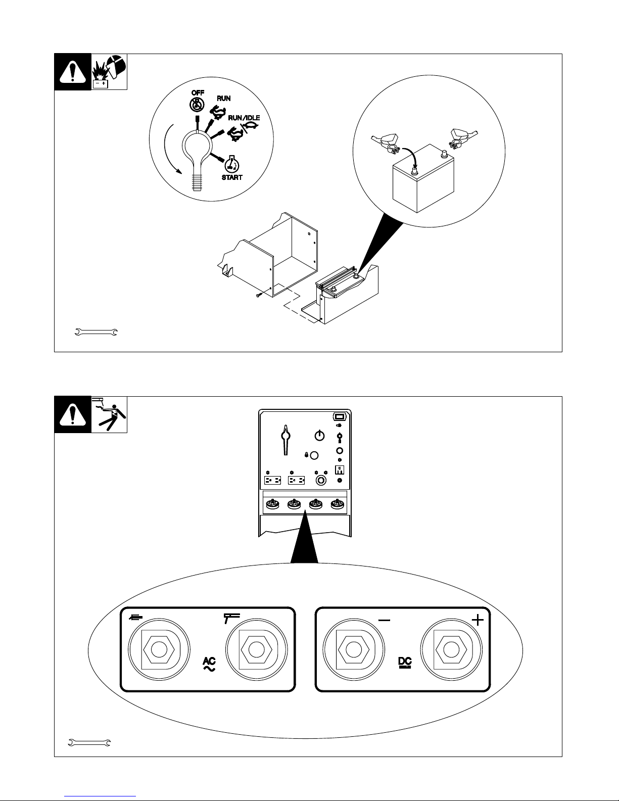
2-5. Connecting The Battery
Tools
Needed:
+
–
3/8, 1/2 in
Y
Connect (–) cable last.
Ref. ST-144 839-F / Ref. ST-168 046 / Ref. S-0756-D
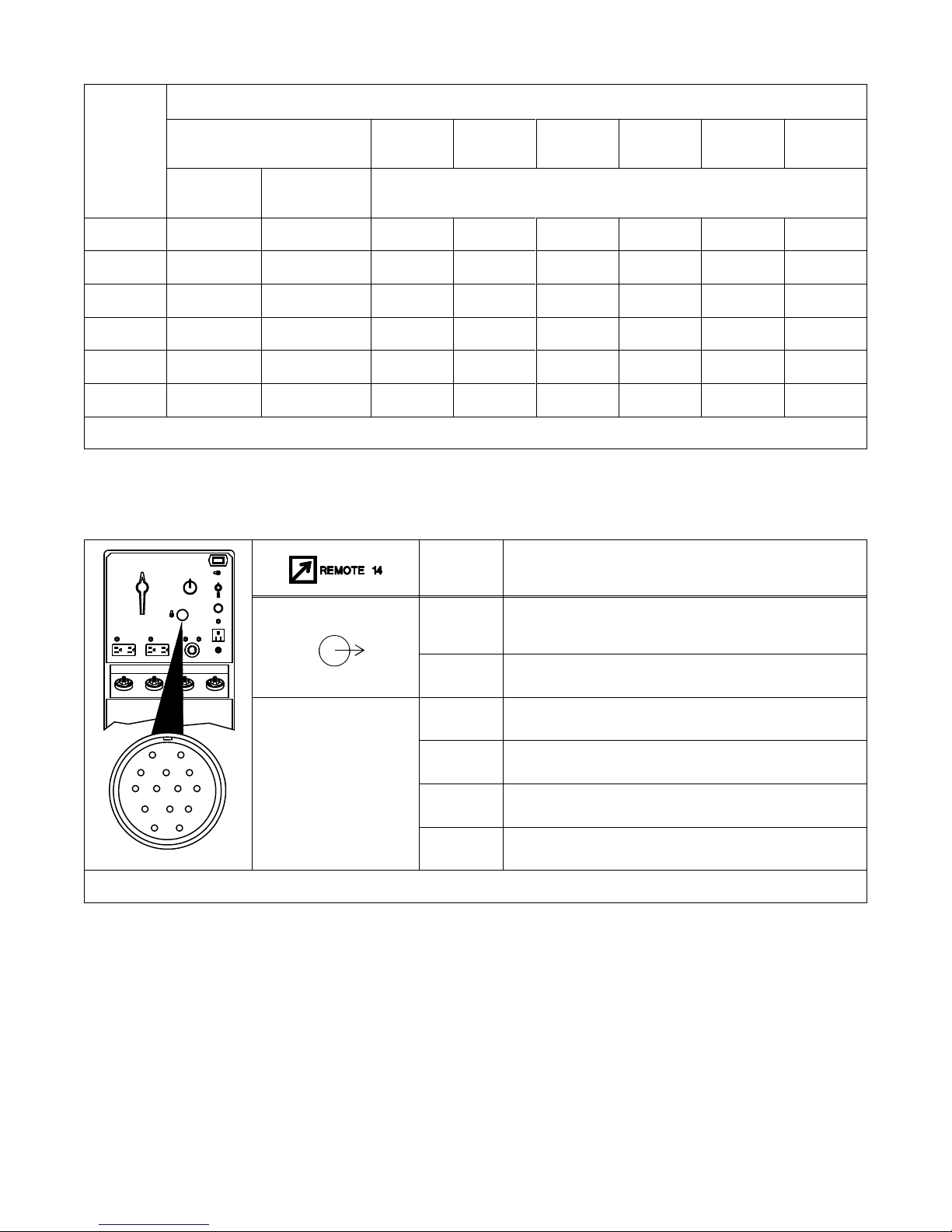
2-6. Connecting To Weld Output Terminals
Y Use ONLY one set of termi-
nals at a time. Disconnect
weld
cables from
set of weld
output
terminals not in use.
ST-140 092-B / Ref. ST-168 046
Tools
Needed:
3/4 in
TM-428 Page 6
Miller Legend
2-7. Selecting Weld Cable Sizes
Total Cable (Copper) Length In Weld Circuit Not Exceeding
100 ft (30 m) Or Less
150 ft
(45 m)
200 ft
(60 m)
250 ft
(70 m)
300 ft
(90 m)
350 ft
(105 m)
400 ft
(120 m)
Welding
Amperes
10 – 60%
Duty Cycle
60 – 100%
Duty Cycle
10 – 100% Duty Cycle
100 4 4 4 3 2 1 1/0 1/0
150 3 3 2 1 1/0 2/0 3/0 3/0
200 3 2 1 1/0 2/0 3/0 4/0 4/0
250 2 1 1/0 2/0 3/0 4/0 2-2/0 2-2/0
300 1 1/0 2/0 3/0 4/0 2-2/0 2-3/0 2-3/0
350 1/0 2/0 3/0 4/0 2-2/0 2-3/0 2-3/0 2-4/0
Weld cable size (A
WG) is based on either a 4 volts or less drop or a current density of at least 300 circular mils per ampere.
S-0007-D
2-8. Remote 14 Receptacle RC1 Information
Socket* Socket Information
A Contact
closure to B completes 15 volts dc contactor control
circuit.
B 15 volts dc.
C +4.5
volts dc output to remote control.
AJ
B
K
I
D Remote
control circuit common.
B
C
L
NH
D
M
G
A
E 0
to +4.5 volts dc input command signal from remote control.
ST-140 092-B
E
F
K Chassis
common.
*The remaining sockets are not used.
TM-428 Page 7
Miller Legend
SECTION 3 – OPERATING WELDING GENERATOR
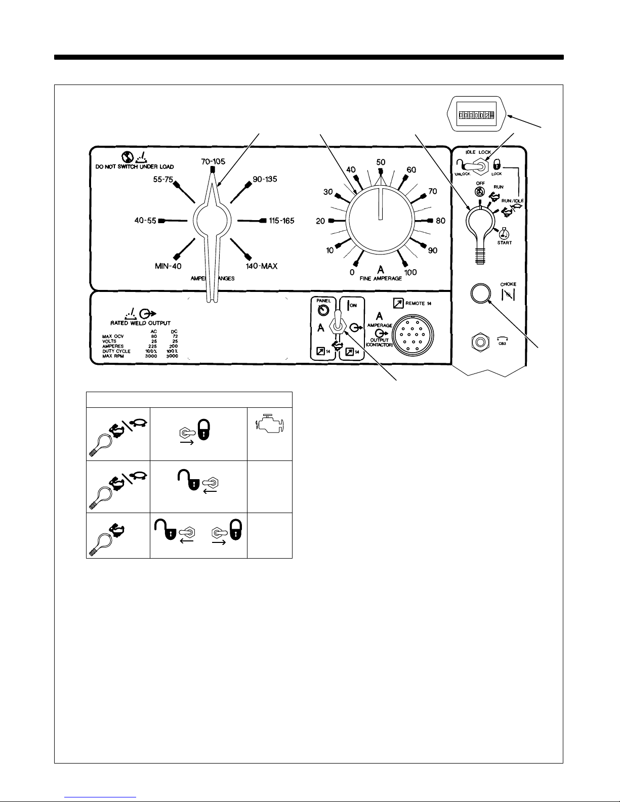
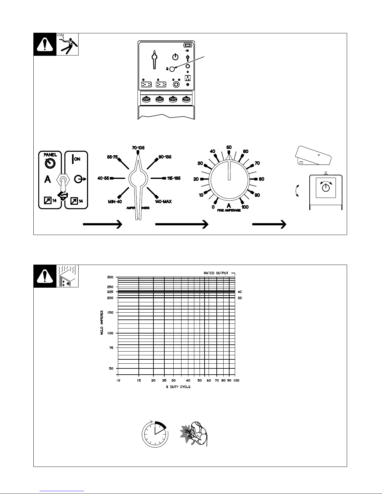
3-1. Front Panel Controls
Ref. ST-168 046
4
2
1 Engine
Control Switch S2
Use switch to start engine, select speed,
and stop engine. In Run/Idle position, engine
runs at power/idle rpm at no load, and
weld/power
rpm under weld or 100 Hz auxil
-
iary
power receptacle load. In Run
position,
engine
runs at weld rpm.
2
Idle Lock Switch S1
Use switch to lock engine at power/idle
speed (see Table). In Unlock position, Engine Control switch and optional Remote
Control
switch determine engine speed.
3
Engine Choke Control
Use control to change engine air-fuel mix.
To Start: pull out choke and turn Engine
Control switch to Start position. Release
switch and slowly push choke in when engine starts. Do not crank engine while flywheel
is turning.
To Stop: turn Engine Control switch to Off
position.
4 Remote
Control Switch S4
Use switch to select front panel or remote
amperage
control (see Section 3-2).
5
Ampere Ranges Switch S5
Use
switch to select weld amperage range.
.
For best arc starts, use lowest amperage
range possible.
6
Fine Amperage Control R1
Use
control to select
weld amperage within
the range selected by the Ampere Ranges
switch.
Control
may be adjusted while weld
-
ing.
Scale is
for reference only
. W
eld output
would be 88 A DC with control settings as
shown
(50% of 70 to 105 A).
7
Engine Hour Meter HM
15
Using Idle Lock Switch
RUN/IDLE
LOCK
UNLOCK
1860 rpm
RUN/IDLE
OR
RUN
LOCKUNLOCK
(Power/Idle)
1860 rpm
(Power/Idle)
No Load:
3000 rpm
Load:
3000 rpm
(Weld)
6 7
3
(Weld)
TM-428 Page 8
Miller Legend
3-2. Remote Control (Optional)
Y Weld output terminals are
energized when Remote
Control switch S4 is in Panel/On
position and engine is
running.
1 Remote
14 Receptacle RC1
Connect
optional remote control
to
RC1
(see Section 2-8).
ST-140 092-B
1
Min (70
A DC)
Max (88
A DC)
Adjust Remote Control
Set Range
Set Percentage
Min = 70
A DC
Percentage Of Range = 50%
Max = 88 A DC (50% of 70 to 105)
In Example:
Set Switch
3-3. Duty Cycle
SB-115 570
Duty
cycle is the percentage of 10
minutes
that unit can weld at
rated
load
without overheating.
Y Exceeding duty cycle can
damage unit and void warranty.
Continuous Welding
100% Duty Cycle at 225 Amperes AC
TM-428 Page 9
Miller Legend
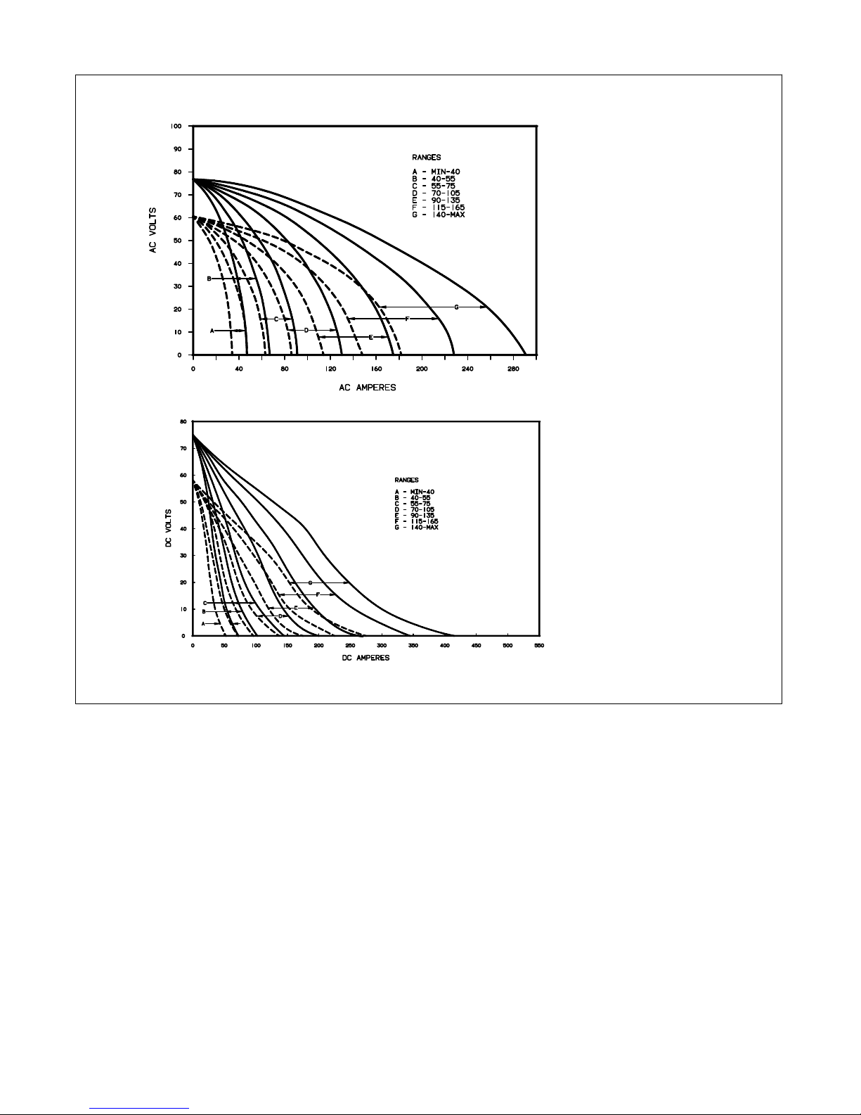
3-4. Volt-Ampere Curves
SB-115 529-A / SB-115 528-A
The volt-ampere curves show the
minimum and maximum voltage
and amperage output capabilities
of
the welding generator
. Curves of
other settings fall between the
curves
shown.
TM-428 Page 10
Miller Legend
SECTION 4 – OPERATING AUXILIARY EQUIPMENT
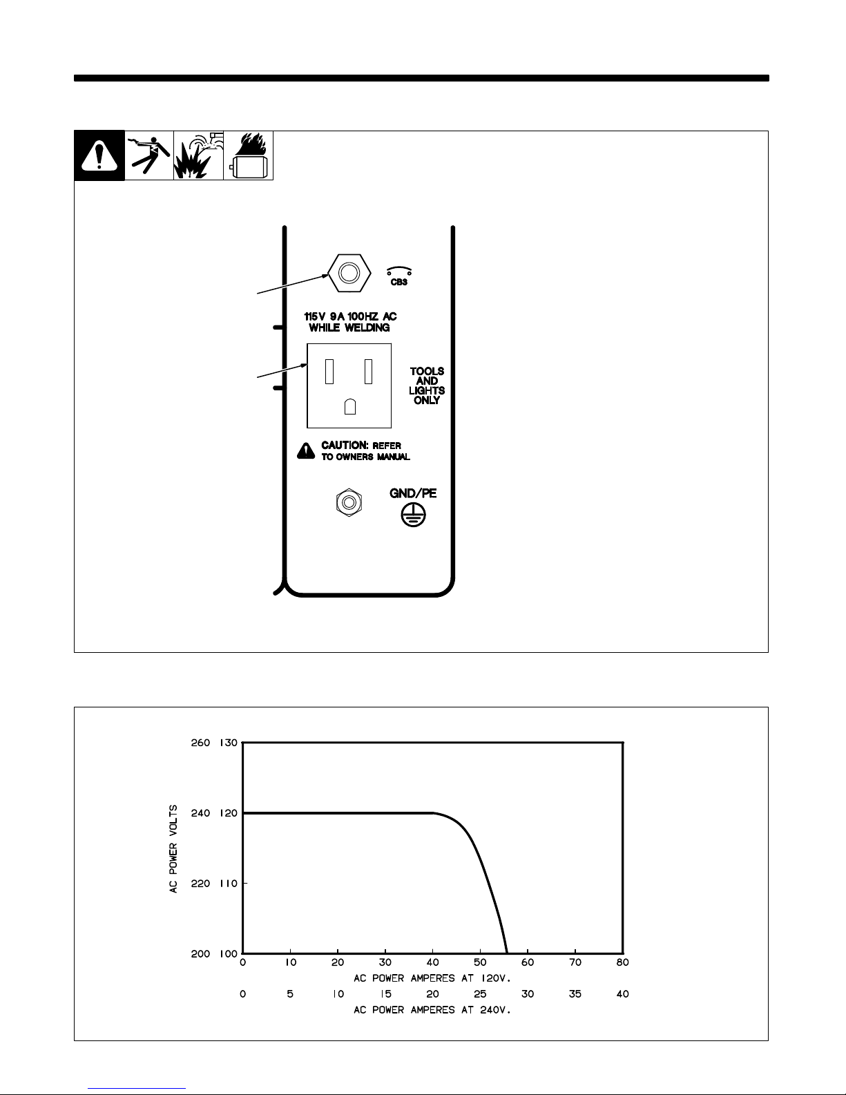
4-1. 100 Hz Auxiliary Power Receptacle And Circuit Breaker
Y Do not operate 50/60 Hz or
60 Hz equipment from 100
Hz
receptacle.
11
15 V 9 A 100 Hz AC Recep
-
tacle RC4
Receptacle supplies single-phase
power at weld speed only. Total
output
available is 1 kV
A/kW.
2 Circuit Breaker CB3
CB3 protects receptacle from
overload.
If CB3 opens, receptacle
does
not work.
2
1
Ref. ST-168 046
4-2. AC Auxiliary Power Curve
SB-115 571
TM-428 Page 1
1
Miller Legend
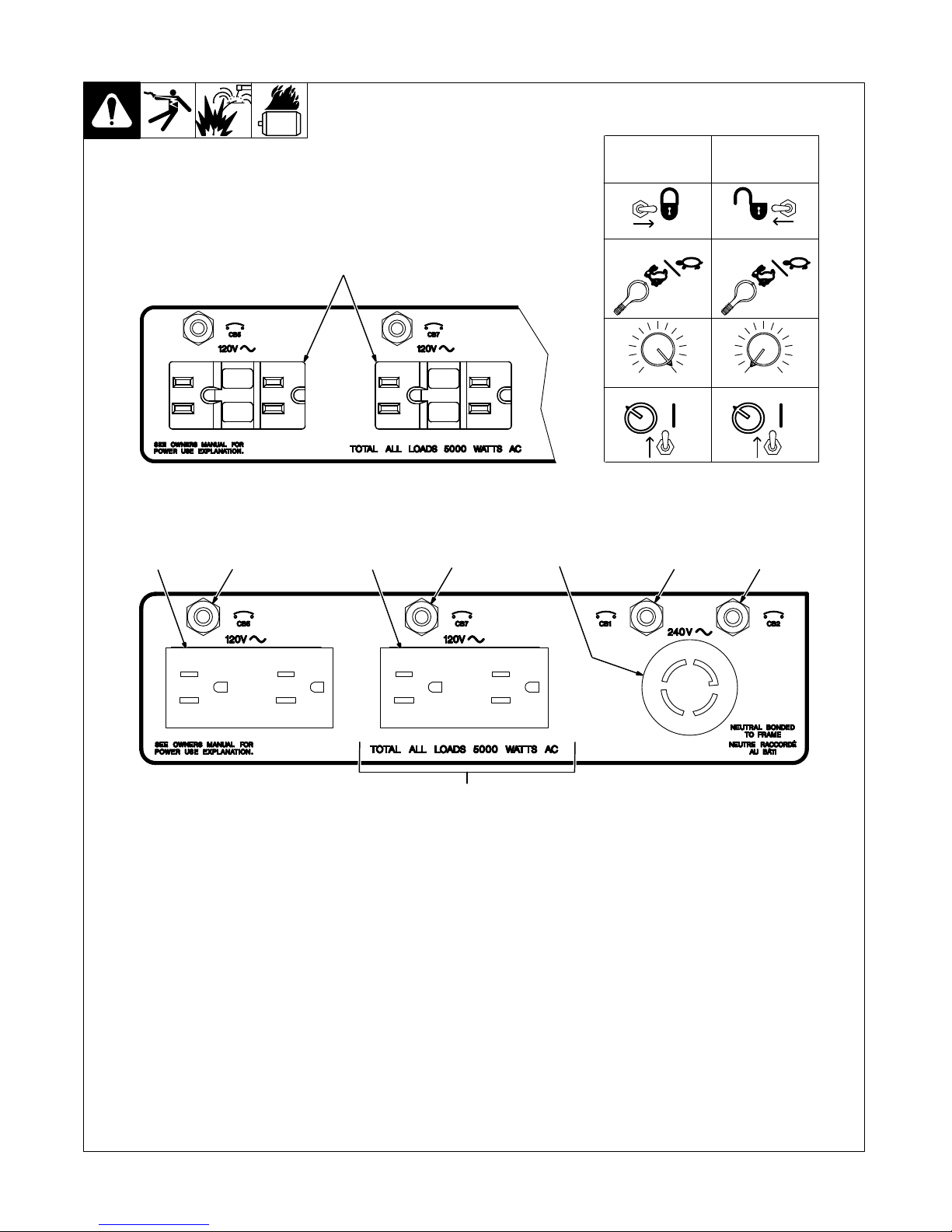
4-3. 60 Hz Auxiliary Power Receptacles And Circuit Breakers
Ref. ST-168 046
5 7812
9
3
4
6
YIf unit does not have GFCI recep-
tacles, use GFCI-protected extension
cord.
1 120
V 15 A AC
Duplex Receptacle RC1
2
120 V 15 A AC Duplex Receptacle RC2
3 240
V 30 A T
wistlock Receptacle RC3
Receptacles supply 60 Hz single-phase
power at power/idle speed only. Maximum
output
from each duplex receptacle
is is 2.5
kVA/kW
. Maximum output from twistlock re
ceptacle is 5 kVA/kW. For 60 Hz auxiliary
power,
set controls as shown in table.
4
120 V 15 A AC Duplex GFCI Recep
-
tacles GFCI1 And GFCI2 (Optional)
If a ground fault is detected, the GFCI recep
-
tacle Reset button pops out and the circuit
opens to disconnect the faulty equipment.
Check
for damaged tools, cords, plugs, etc.
connected
to the receptacle. Press button to
reset
receptacle and resume operation.
.
At least once a month, run engine at
power/idle
speed and press T
est
button
to verify GFCI is working properly.
5 Circuit Breaker CB5
6 Circuit Breaker CB7
CB5 protects RC1 and CB7 protects RC2
from
overload. If CB5 or CB7 opens, the re
ceptacle does not work. Press button to reset
breaker
.
7 Circuit Breaker CB1
8 Circuit Breaker CB2
CB1 and CB2 protect all the 60 Hz recep-
tacles from overload. If CB1 or CB2 opens,
the 240 volt receptacle and one of the 120
volt receptacles does not work. 120 volts
may still be present at the 240 volt receptacle.
Press button to reset breaker
.
9T
otal Auxiliary Power Output
Combined output of receptacles limited to
the 5 kV
A/kW output of the generator:
EXAMPLE:
If 10 A is drawn from a 120 V du
-
plex
receptacle, only 16 A is available at the
240
V receptacle:
(120
V x 10 A) + (240 V x 16 A) = 5.0 kV
A/kW
PANEL
ON
0 100
LOCK UNLOCK
RUN/IDLE RUN/IDLE
PANEL
ON
0 100
For 60 Hz
Auxiliary Power
While W
elding
For 60 Hz
Auxiliary
Power Only
TM-428 Page 12
Miller Legend
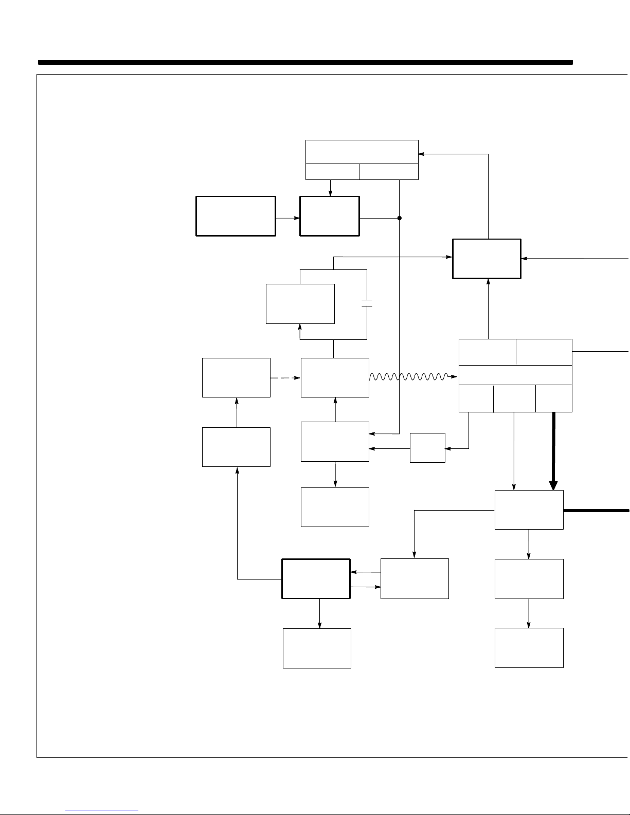
1 Engine
Supplies force to turn revolving
fields.
2 Revolving
Fields (Rotor)
Turn
at 1860 rpm maximum for pow
er/idle and 3000 rpm maximum for
weld.
The speed and excitation cur
rent of the field coils determine volt
ages in stator windings.
3
Stator Windings
Supply power to exciter, auxiliary
power,
and weld circuits.
4
Fuse F1
Protects exciter excitation winding
from
overload.
5
Integrated Rectifier SR2
Changes ac output of stator windings
to dc to supply excitation current
to
the exciter revolving field.
6
Control Relay CR5
Energizes
when voltage is present in
exciter stator to disconnect field
flashing circuit.
7
Idle Module PC1 And Idle Lock
Switch S1
PC1 and S1 control engine speed.
Without
a signal from CT1, PC1 low
-
ers engine speed to power/idle rpm.
8 Throttle
Solenoid TS1
Increases
engine speed to weld rpm
when
energized.
9
Current T
ransformer CT1
Senses output from either weld or
100 Hz auxiliary power windings,
and signals PC1 to increase to or
maintain
weld rpm.
10 Control Relays CR2, CR3, CR4
CR2
energizes at weld rpm to supply
power
to throttle solenoid TS1.
CR3 energizes at power/idle rpm to
bypass
fine amperage control R1.
CR4 energizes at power/idle rpm to
provide 50/60 Hz auxiliary power
output.
11 Voltage
Regulator Board PC2
And T
ransformer T1
PC2 monitors 50/60 Hz auxiliary
power
voltage through T1, and main
-
tains
proper output by adjusting
field
current.
12 Capacitor
Board PC5, Remote
14 Receptacle RC1, Remote
Control Board PC3
PC5
protects unit from high frequen
-
cy.
RC1
connects remote amperage
and contactor control to unit through
control
board PC3.
SECTION 5 – THEORY OF OPERATION
Voltage
Regulator
Board PC2
Current
Transformer
CT1
Circuit
Breaker
CB3
100 Hz
Auxiliary Power
Receptacle RC4
Fuse
F1
Integrated
Rectifier SR2
Revolving
Fields (Rotor)
Fine
Amperage
Control R1
Remote Control
Switch S4
Remote 14
Panel
Remote
Control Board
PC3
Capacitor Board
PC5
And Remote 14
Receptacle RC1
Engine
Idle Module
Control Relays
CR2, CR3, CR4
Idle Lock
Switch S1
12
1
7
10
5
7
16
17
♦
13
♦
12
♦
4
11
9
18
2
PC1
CR3
Throttle
8
Solenoid
TS1
Control
Relay
6
CR5
♦
Voltage
Regulator
60 Hz Auxiliary
Power
Exciter
Stator Windings
3
Weld
100 Hz
Auxiliary
Power
TM-428 Page 13
Miller Legend
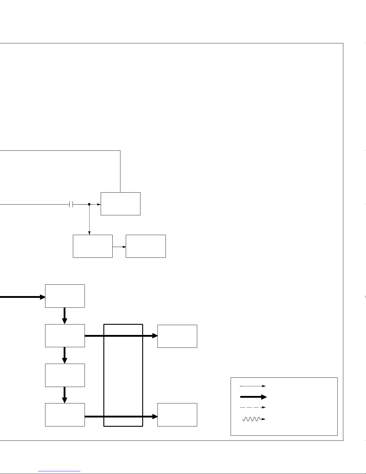
13
Remote Control Switch S4
Selects
Panel or remote
amperage
control.
14 Circuit Breakers CB1, CB2,
CB5, And CB7
Protect 50/60 Hz auxiliary power
receptacles RC1, RC2, and RC3
from
overload.
15
50/60 Hz Auxiliary Power Re
ceptacles RC1, RC2, And
RC3
Provide connection points and
power
for auxiliary equipment.
16 Circuit Breaker CB3
Protects
100 Hz auxiliary power
re
-
ceptacle
RC4 from overload.
17 100 Hz Auxiliary Power Re-
ceptacle RC4
Provides connection point and
power for auxiliary equipment
while
welding.
18
Fine Amperage Control R1
Adjusts
amperage
within range se
lected by Ampere Ranges switch
S5.
19 Ampere
Ranges Switch S5
Selects coarse range of weld output
from weld stator
.
20 Reactor AC-Z
Tapped reactor limits weld output
and
provides coarse ranges.
21
Main Rectifier SR1
Changes ac output from weld
windings
to dc.
22
Stabilizer DC-Z
Smooths out current to dc weld
output
terminals.
23
HF Filter Board PC4
Protects unit from high frequency
.
24
Positive (+) And Negative (–)
DC W
eld Output T
erminals
Provide dc weld output.
25
Electrode And W
ork AC Weld
Output T
erminals
Provide ac weld output.
Stabilizer
Main
Rectifier
SR1
Ampere
Ranges
Switch S5
Reactor
AC-Z
DC-Z
HF Filter
Board
PC4
Positive (+)
And
Negative (–) DC
W
eld Output
Terminals
Transformer
T1
Circuit
Breakers
CB1, CB2,
50/60 Hz
Auxiliary Power
Receptacles
RC1, RC2, RC3
19
20
21
22
11
14 15
23
25
24
Electrode
And
Work AC Weld
Output
T erminals
AC Or DC Control Circuits
Mechanical Coupling
W
eld Current Circuit
Magnetic Coupling
♦ Optional
CR4
CB5, CB7

TM-428 Page 14
Miller Legend
NOTES
TM-428 Page 15
Miller Legend
SECTION 6 – TROUBLESHOOTING
6-1. Troubleshooting Tables
A. Welding
.
See Sections 6-2 and 6-3 for test
points and values and Section 10
for
parts location.
Trouble Remedy
No weld output.
Check fuse F1, and replace if necessary (see Section 8-6).
Check integrated rectifier SR2, and replace if necessary
.
Check diode D4, and replace if necessary
.
Clean slip rings, and install new brushes if necessary (see Section 6-15).
Disconnect leads 21, 23, and 33 from brushes, and check continuity across slip rings. Replace rotor
if necessary.
Check resistance and connections of resistors R2 and R4; R2 and R4 are each 12 ohms
±10%.
Re
-
place resistor(s) if necessary
. Adjust R2 and R4 according to Section 6-16.
Check
resistance and connections of Fine Amperage Control
R1; R1 is 0 to 30 ohms ±10%. Replace
R1
if necessary (see Section 3-1).
Disconnect
leads 22 and 29 from SCR/integrated rectifier SR2, and check for continuity between leads
22
and 29. Replace exciter stator if necessary
.
For
units with optional remote control, check capacitor C5 for a short or open, and check for proper con
-
nections. Replace C5 if necessary.
Check voltage regulator board PC2 and connections, and replace if necessary (see Section 6-9).
No or erratic weld output.
Clean and tighten weld connections both inside and outside unit.
Check engine speed, and adjust if necessary (see Section 8-5).
Check
to make sure Ampere Ranges switch S5 is not between positions. Check continuity of S5, and
replace if necessary.
Check
reactor AC-Z for signs of winding failure. Check continuity across windings, and check for proper
connections. Replace AC-Z if necessary.
Check
resistance and connections of Fine Amperage control R1; R1 is 0 to 30 ohms ± 10%. Replace
R1 if necessary.
Disconnect leads 21, 23, and 33 from brushes, and check continuity across slip rings. Replace rotor
if necessary.
No or erratic DC weld output only
.
Check modular main rectifier SR1, and replace if necessary
.
Check stabilizer DC-Z for signs of winding failure. Check continuity across windings, and check for
proper connections. Replace DC-Z if necessary.
Low or high weld output.
Check engine speed, and adjust if necessary (see Section 8-5).
Adjust resistor R4 slider until 128 to 132 volts ac is obtained at 100 Hz receptacle RC4 (see Section
6-16).
Adjust
resistor R2 slider until proper open-circuit-voltage is obtained at
weld output terminals (see Sec
-
tion
6-16).
Check
resistance
and connections of resistor R3 on suppressor R3, VR1 module; R3 is 1000 ohms
±
10%.
Replace R3, VR1 module if necessary
.
Check
reactor AC-Z for signs of winding failure. Check continuity across windings, and check for proper
connections. Replace AC-Z if necessary.

TM-428 Page 16
Miller Legend
B. 50 Or 60 Hz Auxiliary Power
Trouble Remedy
No auxiliary power output at receptacles RC1, RC2, or RC3.
Run engine at power/idle speed.
Reset circuit breakers CB1 and CB2. Effective with Serial No. KE629034, also reset circuit breakers
CB5
and CB7 (see Section 4-3).
Check
receptacles RC1, RC2, RC3 for continuity and proper connections. Replace receptacle(s) if nec
-
essary.
Check
connections to terminal strip 1T
.
Clean slip rings, and install new brushes if necessary (see Section 6-15).
Check
coil voltage and connections of control relay CR4. Check continuity of coil and condition of
con
-
tacts. Replace CR4 if necessary.
Check diode D4, and replace if necessary
.
Check idle board/module PC1 and connections (see Section 6-5).
Check
control transformer T1 for signs of winding failure. Check continuity across windings, and check
for
proper connections. Check primary and secondary voltages. Replace T1 if necessary
.
Disconnect leads 21, 23, and 33 from brushes, and check continuity across slip rings. Replace rotor
if necessary.
Disconnect
leads 48 and 49
from voltage regulator board PC2, and check continuity between leads 48
and
49. Disconnect leads 50, 51, 52, and 53 from stator
. Check continuity between leads 50 and 51,
and 52 and 53. Replace stator if necessary
.
Low auxiliary power output.
Check connections to terminal strip 1T
.
Clean slip rings, and install new brushes if necessary (see Section 6-15).
Check integrated rectifier SR2, and replace if necessary
.
Check
coil voltage and connections of control relay CR3. Check continuity of coil and condition of
con
-
tacts. Replace CR3 if necessary.
Check voltage regulator board PC2 and connections, and replace if necessary
.
High auxiliary power output.
Check engine speed, and adjust if necessary
.
Check voltage regulator board PC2 and connections, and replace if necessary (see Section 6-9).
C. 100 Hz Auxiliary Power
Trouble Remedy
No
auxiliary power output at receptacle
RC4.
Run
engine at weld speed.
Reset circuit breaker CB3 (see Section 4-1).
Check receptacle RC4 for continuity and proper connections. Replace receptacle if necessary
.
Disconnect
leads 90, 91, 92, and 93 from stator
. Check continuity between leads 90 and 91, and 92 and
93. Replace stator if necessary.
Check diode D4, and replace if necessary
.

TM-428 Page 17
Miller Legend
D. Engine
Trouble Remedy
Engine will not start.
Check fuel level (see Section 2-4).
Check battery and engine charging system according to engine manual.
Check continuity of Engine Control switch S2, and replace if necessary
.
See engine manual.
Engine starts but
stops as soon as En
gine Control switch S2 returns to Run
position.
Check
oil
level (see Section 2-4). Check low oil pressure shutdown switch S3 (see engine parts manual
for
location). S3 should close when engine is running.
Check
and refill crankcase with proper
viscosity oil for operating temperature, if necessary (see engine
manual).
Check
continuity of Engine Control switch S2, and replace if necessary
.
Engine stopped during normal operation.
Check
oil
level (see Section 2-4). Check low oil pressure shutdown switch S3 (see engine parts manual
for
location). S3 should close when engine is running.
Check continuity of Engine Control switch S2, and replace if necessary
.
Battery discharges between uses.
Make
sure Engine Control switch
S2 is placed in the Of
f position when engine is not in use (see Section
3-1).
Prior
to Serial No. KA780044, check fuse F2 and replace if necessary
.
Clean battery, terminals and posts with baking soda solution; rinse with clear water
.
Periodically recharge battery (approximately every 3 months).
Check voltage regulator according to engine manual.
Replace battery
.
Engine idles, but does not come up to
weld
speed.
W
ait 10 seconds for throttle solenoid circuit breaker CB4 to reset (see Section 8-6).
Place Idle Lock switch S1 in Unlock position (see Section 3-1).
Check continuity and connections of current transformer CT1, and replace if necessary
.
Check continuity of Engine Control switch S2, and replace if necessary
.
Check
coil voltage and connections of control relay CR2. Check continuity of coil and condition of
con
-
tacts. Replace CR2 if necessary.
Check diode D6 in throttle solenoid TS1 circuit, and replace if necessary
.
Check resistance at throttle solenoid TS1 terminals. With plunger out, resistance is less than 1 ohm.
With plunger bottomed, resistance is 17 ohms
±10%.
Check throttle linkage for smooth, non-binding operation.
Check idle board/module PC1 and connections, and replace if necessary (see Section 6-5).
Engine does not return to idle speed.
Remove weld load.
Check continuity of Engine Control switch S2, and replace if necessary
.
Check throttle linkage for smooth, non-binding operation.
Unstable or sluggish engine speeds.
Readjust throttle linkage if necessary
.
T
une-up engine according to engine manual.
 Loading...