

Miller Electric Gyro Bail-15/25, Gyro Bail-15, Gyro Bail-25 Owner's Manual
OWNER’S MANUAL
Gyro Bail-15/25 (041 979)
WARNING
OM-714 147 531B
November 1998
ELECTRIC SHOCK can kill.
• Do not touch live electrical parts.
MOVING PARTS can cause injury.
• Keep away from pinch points.
• Turn Off spot welder and input disconnect device.
• Disconnect input power plug or conductors from
deenergized supply BEFORE moving spot welder.
Part
10
Item
8
No.
No.
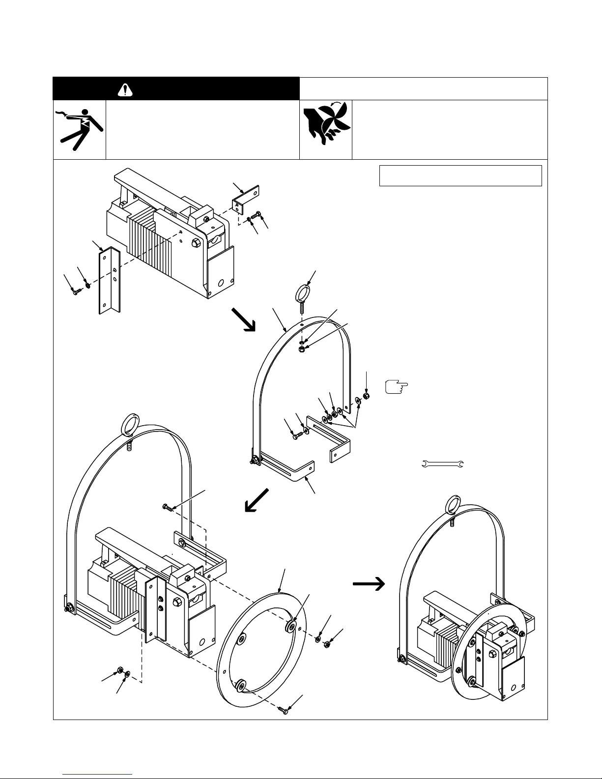
1 601 926 Screw, 1/4-20 x 5/8 (4)
2 602 207 Washer, 1/4 lock (4)
3 147 530 Mounting Bracket LH (1)
4 147 529 Mounting Bracket RH (1)
5 147 527 Suspension Y oke (1)
6 110 510 Eye Bolt (1)
7 602 213 Washer, 3/8 split lock (5)
8 010 909 Nut, 3/8-16 (3)
9 601 871 Nut, 3/8-16 jam (7)
10 602 243 Washer, 3/8 flat (8)
11 142 156 Screw, 3/8-16 x 1-3/4 (2)
12 147 528 Gyro Bail Bracket (2)
13 601 965 Screw, 3/8-16 x 1 (5)
14 110 509 Ring (1)
15 024 665 Bearing (3)
16 602 221 Washer, 3/8 tooth lock (3)
Be sure to provide Model when ordering replacement parts.
Adjust the pivot point or tilt angle of
the spot welder by loosening the two
self-locking nuts (8) and sliding the
spot welder along the gyro bail
brackets (12).
Description (Qty)
Tools Needed:
4
3
2
1
1
2
6
5
10
11
7
8
9
7
3/8, 9/16, 5/8 in
13
14
9
16
12
15
7
9
13
ST-147 722-A / ST-800 191
Figure 1. Gyro Bail-15/25 Assembly
 Loading...