

Specifications and Main Features
- Type of Output: Constant Current/Direct Current (CC/DC)
- Rated Weld Output: 90 Amperes 25 Volts DC at 60 Percentage Duty Cycle
- Amperage Range: 40 to 100A
- Maximum Open-Circuit Voltage: 75 Volts DC
- Welding Process: SMAW; FCAW and GTAW are also possible with selected process options.
- Auxiliary Power Rating: 1.2Kw, 120V D.C, 10 Amperes
- Engine: kand no1-1103, A Turbo cooled, 3-cylinder diesel engine
- Engine Speed: No Load- 1400rpm Idle Speed; 4150rpm Weld & Power Speed
- Fuel Tank Capacity: 2.3 U.S. gal (8.7L)
- Engine Oil Capacity: 22.4 oz (0.66L)
- Drive Belt Size: 1/2 x .343 x 32.3 Cogged
- Overall Dimensions: Detailed in Figure 3-2
- Weight: Net117 kg Ship123 kg
- Options: Not specified.
Frequently Asked Questions
- What type of welding can be performed with the Gold Seal™ Model 3000? The unit is capable of performing Shielded Metal Arc Welding (SMAW), Flux Cored Arc Welding (FCAW), and Gas Tungsten Arc Welding (GTAW) along with the proper process options.
- What is the capacity of the auxiliary power? The auxiliary power rating is 1.2 Kw at 120 Volts DC with maximum output of 10 Amperes.
- What should I do If weld output is Not available to me?
Check the engine speed to see whether it is maintained at the correct level and see whether the generator brushes and slip rings are functioning properly.
- What are the methods to change engine speed?
As per the manual, the throttle control lever and the speed adjustment plate can be utilized to make changes.
- During engine Use, what should I do if I notice issues?
You can look into the troubleshooting section of the manual, or you could reach out to a qualified service station for help.
- Is low oil condition able to turn the engine off automatically?
There is an optional low oil pressure switch which will prevent the engine from turning on when the oil pressure is lower than the set value, so yes it is able to do that.
- Based on the manual, how often should I change the engine oil?
You would be required to change the engine oil after around 100 hours of usage, or as indicated in the maintenance section of the manual.
User Manual
Page 1
Millerfi
March1993
Form:
OM-160518
~.
r.~1~Ic4...1
-
1
~.w
OWNERS
MANUAL
Effective
~_
~
I
With
Serial
No.
KD398640
coven
5/92ASt-161
Read
safety
Have
install,
Call
the
477
and
follow
blocks
trained
only
operate,
distributor
your
directions.
Gold
CC/DC
Welding
For
SMAW
90
Amperes,
1.2
kVA/kW
CH5+
Kohler
these
or
Low
and
service
if
you
Optional
carefully.
SealTM
Generator
Welding
VoltsDCAt
25
DC
Auxiliary
Air-Cooled,
Pressure
Oil
instructions
qualified
unit.
this
do
understand
not
60%
Power
Four-Cycle,
Shutdown
and
all
persons
Model
Duty
With
Overload
Gasoline
Switch
Cycle
3000
Protection
Engine
Give
For
or:
1079,
this
manualtothe
call
help,
MILLER
Appleton,
your
ELECTRIC
WI
operator.
distributor
Mfg.
54912
P.O.
Co.,
414-734-9821
PRINTEDIN~SA
Box
Page 2

Page 3
s
a
u
LIMITED
Co.,
MIg.
MILLER
in
tects
RANT?
IMPLIED,
NESS.
Within
ranted
MILLER
which
followed.
MILLER
event
start
on
and
are
1.
5
*
3
2.
*
*
2
3.
I
4.
*
*
*
*
*
*
5.
6
90
6.
*
*
*
the
pans
lime
of
MILLERS
This
limited
WARRANTY
Appleton.
equipment
material
IS
INCLUDING
must
shall
suchafailure
the
as
Yearn
Yearn
YearsPans
Year
Months
Days
Wisconsin,
sold
end
workmanship
EXPRESSLY
periods
warranty
or
components
notified
be
will
MILLER
honor
warranty
date
that
the
follows:
Pans3
main
Original
Pans
Transformer/Rectifier
Arc
Plasma
Semi-Automatic
Robots
Driven
Engine
(NOTE:
Engines
Pans
and
Driven
Motor
Controllers
Process
Coolant
Water
HF
Units
Grids
Welders
Spot
Banks
Load
SDX
Transformers
Gear/Trailers
Running
Fietd
Options
Field
(NOTE:
period
warranty
one
yaar
Batteries
Pans
Guns/TIG
MIS
Plasma
Cutting
Remote
Controls
warranty
Subject
sfter
the
IN
LIEU
THE
WARRANTIES
listed
that
in
writing
instructions
provide
claimsonwarranted
within
the
equipment
Years
Labor
power
and
Labor
Power
Cutting
and
and
Labor
Welding
are
Labor
Guns
Systems
options
ol
the
whichever
and
Labor
Torches
Torches
supersedes
the
to
terms
wsrrsnts
effective
at
the
OF
ALL
below,
tall
duetosuch
within
warranty
was
rectifiers
Power
Automatic
Generators
warranted
covered
are
product
is
greater.)
(Equipment
end
its
to
dateofthis
timeitis
OTHER
OF
MILLER
(30)
thiny
the
on
time
delivered
Sources
Sources
Wire
separately
under
they
TRUE
all
conditions
originsl
detectsinmaterial
periods.
Feeders
are
MILLER
previous
below,
retell
limited
warranty
shipped
MILLER.
by
WARRANTIES.
MERCHANTABILITY
will
repair
of
such
days
claim
warranty
equipment
All
warranty
the
to
original
the
by
angina
BIuenM
True
installed
in,
with
a
MILLER
purchsser
EXPRESS
or
replace
or
workmanship.
defect
procadurea
listed
retail
manufacturer.)
for
the
for
a
or
BLUETM
Effective
number
serial
endisexclusive
warranties
Electric
that
new
of
de
is
tree
WAR
THIS
OR
FIT
AND
war
any
at
failure,
or
be
to
in
the
below
lime
periods
purchaser,
remaining
of
minimum
January
MILLERS
1.
2.
3.
MILLER
CIALJINDUSTRIAL
THE USE
In
shall
writing
ment
chase
goods
will
vice
TO
ARE
TRACT,
ANY
THEORY
LIMITED
1992
1,
of
preface
withnoother
*
Accessory
*
Replacement
True
Items
furnished
trade
accessories.
any.
Consumabla
and
relays.
Equipment
that
ment
based
upon
and
necessary
of
outside
PRODUCTS
AND
01
the
avant
MILLERS
at
ba,
MILLER
by
authorized
alan
(lass
price
customers
at
ba
FOB.,
Factory
as
facility
for
went
transportation
THE
EXTENT
THE
SOLE
FOR
LIABLE
DAMAGES
RANTY,
REMEDY
OPERATION
CLUDING
FOR
FURNISHED
Some
lasts,
the
citic
In
or
waived.
Warranty
vary
EXPRESS
PARTICULAR
slates
or
above
legal
Canada,
remedies
Irom
DIRECT,
(INCLUDING
TORT
GUARANTY
FOR
WHICH.
ANY
in
the
esciusion
liwitatlon
rights,
legislation
other
Ihe
limitations
provides
province
WARRANTY
KC
or
newer)
Kits
Pans
Limited
MILLER,
by
These
has
bean
been
improperly
standards,
maintenance,
ARE
INTENDED
AND
claim
option:
(1)
appropriate
MILLER
depracialion
risk
and
expense.
atAppleton,
of
costs
EXCLUSIVE
INDIRECT,
LOSS
OTHER
NOT
OR
REPRESENTATION
OF
FOR
THIS
CUSTOM
WARRANTY
EXCLUDED
IS
do
not
of
incidental,
exclusion
other
rights
in
some
and
exclusions
legal
province.
or
Warranty
items
modilied
service
any
WITH
provinces
guerantees
BiuanM
components;
that
has
industry
the
spacifications
USERS
MAINTENANCE
a
warranty
in
reasonable
determinedbyMILLER.
PERMITTED
AND
ANY
OR
WARRANTY
BREACH
BUT
OF
LAW.
IMPLIED
PURPOSE.
BY
MILLER
the
U.S.A.
or
and
thanasstaled
specific
to
warranties
shall
but
manufactured
coveredbythe
are
such
contact
as
by
any
installed,
or
aquipmenl
or
equipment
br
the
equipment.
FOR
PURCHASE
PERSONS
OF
WELDING
covaradbythis
repair;or(2)
the
cases.
(3)
station;
based
MILLERS
Wisconsin,
Therefore
kind
will
BY
THE
LAW,
REMEDIES.INNO
INCIDENTAL
SPECIAL.
OF
PROFIT).
LEGAL
THEORY.
PROVIDED
CONTRACT
PROVISION,
TRADE
OF
OF
RESPECT
AND
allow
limitations
indirect,
special
not
apply
may
be
available,
may
provides
and
herein,
set
out
and
other
rights,
or
eapressed
not
to:
apply
others,
by
manufacturers
tips,
cutting
other
party
improperly
which
which
han
AND
TRAINED
AND
EOUIPMENT
warranty,
replacement;
reasonabia
or
(4)
payment
actual
upon
optionofrepair
P.0.6.
at
or
a
no
compensation
be
allowed.
REMEDIES
EVENT
WHETHER
HEREIN
AND
AS
TO
PERFORMANCE,
TORT
DR
MIGHT
ARISE
OR
COURSE
MERCHANTABILITY
ANY
TO
DISCLAIMED
of
how
or
consequential
This
to
you.
but
may
br
certain
to
the
astant
above
may
rights
may
Implied.
nozzles,
than
operated
has
not
bean
USE
the
where
or,
cost
oforcredit
usa)
MILLER
PROVIDED
OR
ANY
ANY
AND
an
long
warranty
vary
additional
that
not
be
such
MILLER.
EXPERIENCED
eacluniva
of
SHALL
CONSEOUENTIAL
BASED
BY
OF
ALL
BY
from
apply.
available,
as
anginea
warranty,
conlaclorn
or
equip
misused
or
had
reasonable
used
for
operation
BY
COMMER
remedies
authorized
repairorreplace
for
the
return
or
replacement
authorized
raimburse
or
HEREIN
MILLER
ON
IMPLIED
AND
OTHER
IMPLICATION,
DEALING.
OR
FITNESS
EOUIPMENT
MILLER.
implied
warranty
damages,
provides
stale
to
warranties
they
may
This
but
of
CON
WAR
LEGAL
stale.
not
Limited
upon
or
it
IN
in
pur
the
ser
BE
ANY
IN
ao
spa
ba
may
I
_____________________________
Before
with
the
Transportation
When
the
USe
or
namep(ate.
unpacking
delivering
Department.
requesting
following
equ(pment,
carrier.
infDrmation
to
spaces
Model
Serial
DateofPurchase
check
Assistance
about
record
__________
or
Style
carton
this
Model
for
any
for
or
filing
equipment,
Designation
No.
RECEIVING-HANDLING
damage
settling
always
and
that
provide
Serial
may
claims
or
have
may
Mode)
Style
occurred
be
obtained
Designation
Number
of
during
from
your
Shipment.
distributor
and
Serial
The
unit.
File
and/or
or
Sty(e
information
claims
any
equipment
Number.
is
located
for
loss
manufacturers
the
on
or
damage
rating
label
miller
r
I
5192
Page 4

Page 5
March
1
993
Form:
OM-160
518
1~oIsfi
OWNERS
MANUAL
Effective
(jJOJ1
With
Serial
cI~j\r~J~
No.
KD398640
cover
8/92
ST-161
PAW
CC/DC
Welding
For
SMAW
U
90
Amperes,
U
1.2
kVAJkW
Kohler
CH5+
Optional
U
Read
and
follow
blocks
safety
Have
U
U
477
only
install,
operate,
Callyourdistributorifyoudonotunderstand
the
directions.
these
carefully.
trained
or
and
service
Generator
Welding
VoltsDCAt
25
DC
Auxiliary
Air-Cooled,
Low
Oil
Pressure
instructions
qualified
this
unit.
Power
Four-Cycle,
and
persons
60%
With
Shutdown
all
100
Duty Cycle
Overload
Gasoline
Switch
rt~i
Protection
Engine
U
Give
U
For
U
or:
1079,
this
manualtothe
call
help,
MILLER
Appleton,
distributor
your
ELECTRIC
WI
operator.
Mfg.
54912
P.O.
Co.,
414-734-9821
PRINTED
Box
IN
~SA
Page 6

Page 7
PROTECT
AWAY.
In
welding,
information
safety
Safety
HAVE
Standards
ALL
QUALIFIED
1.
Do
not
Wear
2.
Insulate
3.
mats
4.
Disconnect
servicing
a
YOURSELF
PACEMAKER
in
as
INSTALLATION,
PEOPLE.
ELECTRIC
Touching
severe
or
electrically
power
when
live
wire
welding,
all
and
electrically
grounded
live
touch
hole-free
dry,
yourself
covers.
or
input
this
equipment.
ARC
WARNING
most
jobs,
given
listed
live
burns.
live
circuit
power
metal
live.
equipment
electrical
insulating
from
power
WELDING
AND
WEARERS
exposure
below
the
on
SHOCK
electrical
The
whenever
and
machine
is
on.
the
wire,
parts
Incorrectly
parts.
gloves
work
and
or
stop
OTHERS
KEEP
is
only
next
page.
OPERATION,
can
can
parts
electrode
the
output
internal
In
semiautomatic
wire
reel,
installed
hazard.
a
and
ground
engine
the
body
touching
is
FROM
AWAY
certain
to
a
summary
Read
kill.
cause
work
and
is
circuits
drive
welding
or
protection.
using
dry
before
SAFETY
POSSIBLE
UNTIL
hazards
of
the
and
follow
MAINTENANCE,
fatal
shocks
is
circuit
The
on.
input
also
are
automatic
or
roll
housing,
wire
are
improperly
insulating
installing
or
SERIOUS
CONSULTING
occurs.
more
Welding
complete
all
Safety
AND
5.
Properly
Owners
When
6.
conductor
7.
Turn
Do
8.
cables.
Do
9.
Ground
10.
11.Donot
12.
Use
damaged
Wear
13.
14.
Keep
PRECAUTIONS
ARC
WELDING
Standards.
REPAIR
install
Manual
making
off
all
not
use
not
wrap
the
touch
only
a
safety
all
panels
INJURY
YOUR
is
safety
first.
equipment
cables
workpiece
well-maintained
parts
DOCTOR.
safe
information
WORK
and
and
input
worn,
electrode
at
once.
harness
and
OR
when
ground
national,
connections,
when
damaged,
around
to
a
if
in
if
working
covers
be
can
DEATH.
hazardous.
KEEP
precautions
will
that
PERFORMED
this
equipment
and
attach
use.
body.
electrical
with
the
floor
above
local
(earth)
Repair
state,
in
not
undersized,
your
good
contact
equipment.
securelyinplace.
CHILDREN
taken.
are
be
found
ONLY
according
codes.
proper
or
poorly
ground.
work
or
level.
The
in
the
BY
to
grounding
spliced
ground.
or
replace
its
1.
Use
1.
Keep
If
2.
inside,
remove
If
ventilation
3.
4.
Read
manufacturers
and
1.
Protect
Do
2.
Remove
3.
this
4.
Be
approved
your
ventilate
welding
the
cleaners.
yourself
weld
not
all
not
is
alert
that
through
RAYS
ARC
NOISE
Arc
heat
and
rays
and
skin.
can
from
strong
Noise
hearing.
ear
plugs
FUMES
to
your
produces
Welding
fumes
and
out
head
the
fumes
is
poor,
Material
instruction
WELDING
and
Sparks
sparks
flying
workpiece,
Accidental
burns.
metal
to
fire.
possible,
and
where
flying
flammables
welding
small
objects
tightly
FLYING
cause
Chipping
cool,
injury.
and
they
can
damage
the
welding
ultraviolet
from
or
ear
AND
GASES
health.
fumes
can
gases
of
fumes.
the
and/or
area
and
gases.
use
an
approved
Data
Safety
for
can
spatter
and
and
hot
contactofelectrode
can
from
others
sparks
within
cover
and
sparks
cracks
SPARKS
grinding
throw
can
burn
hearing.
process
rays
some
processes
muffsifnoise
can
and
be
hazardous
Do
not
use
air-supplied
Sheets
consumables,
metals,
cause
off
from
fly
hot
metal,
equipment
cause
sparks,
flying
strike
can
ft
35
(10.7
them
with
hot
materials
and
openings
AND
cause
off
slag.
eyes
that
be
gases.
breathe
exhaust
(MSDS5)
fire
the
weld
can
sparks
flammable
of
m)
approved
HOT
flying
and
produce
burn
can
can
damage
level
is
high.
hazardous
Breathing
health.
to
your
the
fumes.
the
at
respirator.
and
coatings,
or
explosion.
arc.
welding
spatter,
fires
cause
orwelding
overheating,
and
hot
material.
the
welding
covers.
from
welding
to
adjacent
METAL
As
metal.
skin;
intense
eyes
these
arc
the
The
hot
and
wire
metal.
arc.
can
areas
can
welds
RAYS
ARC
2.
Wear
a
ANSI
Z49.
when
eyes
Wear
3.
4.
5.
5.
Use
protective
and
glare;
Wear
material
Work
approved
protective
in
wearing
welding
breathing
Do
weldinlocations
not
6.
operations.
form
to
7.
Do
not
cadmium
weld
highly
area,
wearing
containing
for
Watch
5.
Be
6.
aware
can
cause
weld
Do
not
7.
or
8.
Connect
practical
unknown
Do
9.
not
use
Remove
10.
If
11.
1.
2.
contact
Wear
shirt,
Wear
Wear
oil-free
cuffless
approved
recommended.
proper
helmet
welding
listed
1
welding
safety
screens
others
warn
and
(wool
confined
a
an
air-supplied
can
displace
air
is
safe.
The
heat
toxic
weld
tip
coated
on
steel,
plated
the
area
an
air-supplied
these
and
fire,
that
welding
fire
on
closed
on
work
cable
to
prevent
and
paths
welder
stick
electrode
when
protective
trousers,
body
in
Safety
or
clothing
leather)
space
and
elements
keep
the
to
welding
causing
to
not
face
protection
with
fitted
Standards)
watching.
glasses.
barriers
or
watch
not
to
made
and
only
respirator.
air
causing
near
degreasing,
and
of
rays
irritating
gases.
metals,
unless
the
is
well
ventilated,
respirator.
can
give
fire
a
extinguisher
a
on
ceiling,
hidden
side.
containers
workasclosetothe
the
current
electric
frozen
thaw
from
in
holder
use.
garments
shoes,
high
shield
or
to
a
proper
to
Side
shields
to
protect
the
arc.
from
durable,
foot
protection.
if
itiswell
Shielding
or
injury
the
arc
can
such
as
coating
and
The
coatings
off
toxic
floor,
suchastanks
from
traveling
shock
pipes.
cut
or
such
as
and
a
safety
goggles.
skin.
protect
shadeoffilter
protect
your
recommended.
others
from
flame-resistant
ventilated,
gases
death.
Be
react
or
with
cleaning,
galvanized,
is
removed
if
necessary,
and
any
if
fumes
nearby.
bulkhead,
or
or
drums.
welding
long,
and
fire
hazards.
off
welding
leather
gloves,
cap.
Side
(see
face
and
flash
while
or
for
used
the
sure
spraying
to
vapors
or
lead,
from
the
while
metals
welded.
partition
area
as
possibly
wire
at
heavy
shields
srI
9/92
Page 8

Page 9
IL~c
Protect
mechanical
2.
Install
and
them
to
prevent
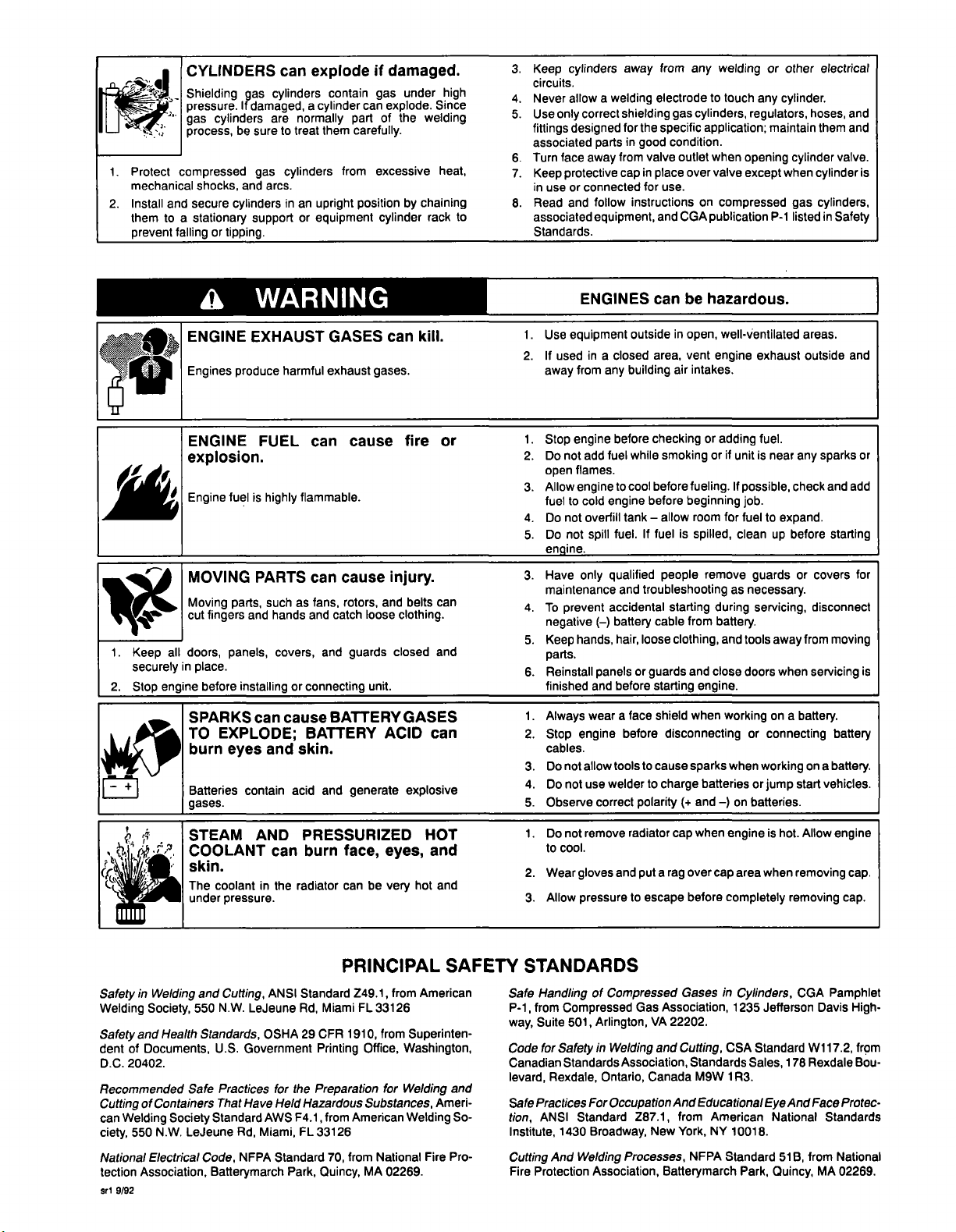
CYLINDERS
Shielding
pressure.
gas
process,
compressed
shocks,
secure
a
stationary
gas
If
damaged,
cylinders
be
sure
gas
and
cylinders
support
arcs.
fallingortipping.
can
explode
cylinders
a
cylinder
are
normally
to
treat
cylinders
in
an
upright
or
equipment
contain
them
from
if
damaged.
under
gas
can
explode.
of
the
part
carefully.
excessive
position
by
cylinder
high
Since
welding
heat,
chaining
to
rack
3.
Keep
circuits.
Never
4.
Use
5.
fittings
associated
Turn
6.
7.
in
8.
associated
cylinders
allow
only
designed
face
protective
Keep
use
or
Read
and
Standards.
a
welding
correct
shielding
for
parts
from
away
cap
connected
follow
equipment,
from
away
electrode
the
specific
in
good
valve
in
place
for
use.
instructions
and
any
to
cylinders,
gas
application;
condition.
outlet
when
over
on
CGA
publication
welding
touch
any
regulators,
opening
valve
except
compressed
other
or
cylinder.
maintain
cylinder
when
gas
P-i
listed
electrical
and
hoses,
and
them
valve.
cylinder
cylinders.
in
Safety
is
1.
securely
2.
Keep
Stop
a
ENGINE
Engines
ENGINE
explosion.
Engine
MOVING
Moving
cut
fingers
all
doors,
in
place.
before
me
en
SPARKS
TO
burn
Batteries
gases.
WARNING
EXHAUST
produce
fuel
parts,
panels,
EXPLODE;
eyes
harmful
FUEL
is
PARTS
and
highly
such
hands
covers,
can
flammable.
can
as
fans,
and
installingorconnecting
cause
can
BATTERY
skin,
and
contain
acid
GASES
exhaust
cause
cause
rotors,
catch loose
and
guards
BATTERY
and
generate
can
gases.
injury.
and
closed
unit.
ACID
kill.
fire
or
belts
can
clothing.
and
GASES
can
explosive
1.
Use
If
2.
away
1.
Stop
2.
Do
open
Allow
3.
fuel
Do
4.
Do
5.
engine.
Have
3.
maintenance
To
4.
negative
5.
Keep
parts.
Reinstall
6.
finished
1.
Always
2.
Stop
cables.
Do
3.
4.
Do
Observe
5.
ENGINES
equipment
in
used
from
engine
add
not
flames.
engine
cold
to
overfill
not
not
spill
only
prevent
hands,
and
wear
engine
allow
not
not
use
outside
closed
a
building
any
before
while
fuel
cool
to
engine
tankallow
fuel.Iffuel
qualified
and
troubleshooting
accidental
battery
()
loose
hair,
or
panels
before
face
a
before
tools
to
welder
correct
polarity
be
in
air
open,
vent
intakes.
hazardous.
or
can
area,
checking
smoking
before
fueling.
before
beginning
room
is
spilled,
remove
people
starting
from
cable
clothing,
and
guards
starting
engine.
when
shield
disconnecting
cause
sparks
charge
(+
batteries
and
to
well-ventilated
exhaust
engine
fuel.
adding
if
unit
is
or
near
If
possible,
job.
for
fuel
to
clean
up
guards
as
necessary.
during
servicing,
battery.
and
tools
close
doors
on
working
or
connecting
when
working
or
iump
batteries.
on
)
areas.
any
check
expand.
before
or
away
when
a
battery.
start
and
outside
sparks
and add
starting
covers
disconnect
from
moving
servicing
battery
on
a
battery.
vehicles.
or
for
is
4
~
(.~
~
.
~
The
SafetyinWelding
Welding
Safety
dent
D.C.
Recommended
Cutting
can
ciety,
National
tection
Sri
Society,
and
of
Documents,
20402.
of
Welding
550
Electrical
Association,
9/92
Health
Safe
Containers
Society
N.W.
LeJeune
STEAM
COOLANT
skin.
coolant
under
pressure.
and
Cutting,
N.W.
550
Standards,
U.S.
Practices
That
Standard
Rd,
Code,
Batterymarch
AND
can
in
the
ANSI
LeJeune
OSHA
Government
for
Have
Held
AWS
Miami,
NFPA
Standard
PRESSURIZED
burn
radiator
Standard
MiamiFL33126
Rd,
CFR
29
Printing
the
Preparation
Hazardous
from
F4.i
FL
33126
70,
Park,
Quincy,
face,
eyes,
be
can
very
PRINCIPAL
from
Z49.1,
from
1910,
Office,
Washington,
for
Welding
Substances,
American
from
National
MA
Welding
02269.
HOT
and
h
and
ot
SAFETY
American
Superinten
and
Ameri
So
Fire
Pro
1.
Do
cool.
to
2.
Wear
Allow
3.
STANDARDS
Safe
Handling
from
P-i,
Suite
way,
for
Code
Canadian
levard,
Safe
tion,
Institute,
Cutting
Fire
Safety
Rexdale,
Practices
ANSI
1430
And
Protection
not
remove
and
gloves
pressure
of
Compressed
Compressed
501,
Arlington,
in
Standards
Welding
Association,
Ontario,
ForOccupationAnd
Standard
Broadway.
Processes,
Welding
Association,
radiator
a
put
to
escape
Gas
Association,
VA
and
Canada
Z87.1,
New
Batterymarch
when
cap
over
rag
before
Gases
22202.
Cutting,
Standards
M9W
Educational
from
York,
NFPA
engine
area
cap
completely
in
Cylinders,
1235
CSA
Sales,
1R3.
American
NY
10018.
Standard
Park,
is
hot.
when
removing
Jefferson
Standard
178
And
Eye
National
51
Quincy,
Allow
engine
removing
CGA
Pamphlet
Davis
Wi
17.2,
Rexdale
Face
Standards
from
B,
MA
cap.
cap.
High
from
Bou
Protec
National
02269.
Page 10

Page 11
22334566
SECTION
SECTION
2-1.
2-2.
2-3.
2-4.
SECTION
3-1.
3-2.
3-3.
3-4.
SECTION
SECTION
5-1.
5-2.
-
1
SAFETY
2
SPECIFICATIONS
Volt-Ampere
Cycle
Duty
Fuel
Consumption
DC
Auxiliary
3INSTALLATION
Selecting
Engine
A
Prestart
Grounding
Connecting
4OPERATING
OPERATING
5
Auxiliary
Auxiliary
Power
Equipment
SIGNAL
Curves
Power
Location
Checks
The
Generator
Weld
To
DC
TABLE
WORDS
Curve
And
Output
THE
WELDING
AUXILIARY
Receptacle
Operation
OF
.
Moving
Auxiliary
Welding
Terminals
GENERATOR
EOUIPMENT
CONTENTS
Generator
Power
System
1
7
10
10
SECTION
6-1.
6-2.
6-3.
6-4.
6-5.
6-6.
6-7.
6-8.
SECTION
SECTION
8-1.
8-2.
SECTION
Figure
Figure
Figure
MAINTENANCE
6
Routine
Changing
Adjusting
Air
Clean
Drive
Overload
Maintenance
Cleaner
Air
Belt
Engine
Engine
Service
Intake
Adjustment
Protection
Troubleshooting
7
ELECTRICAL
WELDING
8-
Shielded
Welding
PARTS
9
Main
9-1.
9-2.
Panel,
9-3.
Panel,
METHODS
Arc
Metal
Troubleshooting
LIST
Assembly
Front
Control
&
TROUBLESHOOTING
Oil
Speed
And
Cooling
And
Replacement
DIAGRAMS
&
TROUBLESHOOTING
Welding
(SMAW)
w/Components
w/Components
Areas
11
12
13
13
14
14
15
16
18
20
25
28
31
32
OM.160
518
3)93
Page 12

Page 13
Read
Obey
Learn
SECTION
all
safety
messages
all
safety
messages
the
meaning
of
WARNING
1
throughout
avoid
to
injury.
and
SAFETY
this
manual.
CAUTION.
SIGNAL
WORDS
rnodl.1
2/93
1
2
L~
/
5
6
NOTE
7H
;
ELECTRIC
I
Do
I
Disconnect
installingorservicing.
SHOCK
touch
live
not
input
~
kill
can
electrical
parts.
power
betore~
Off
switch
Turn
SECTION
3
_______________
~
READ
Section
when
using
Figure
2
2
\
a
CAUTION
1-1.
SAFETY
3-1
high
Safety
MOVING
before
frequency.
Keep
away
all
Keep
panels
when
operating.
BLOCKS
proceeding
Information
PARTS
from
SPECIFICATIONS
______________
at
can
moving
and
start
parts,
covers
of
injure.
closed
I
I
I
1
Safety
2
Signal
WARNING
serious
or
CAUTION
or
injury
happen.
Statement
3
Result
4
Safety
Hazard
Hazard
5
6
Safety
Read
safety
bol
shown.
7
NOTE
Special
ation
Alert
Word
means
injury
means
equipment
Of
Instructions
Symbol
Banner
blocks
instructions
related
not
Symbol
possible
can
happen.
possible
damage
Hazard
(If
for
for
to
safety.
death
minor
can
And
To
Avoid
Available)
each
sym
best
oper
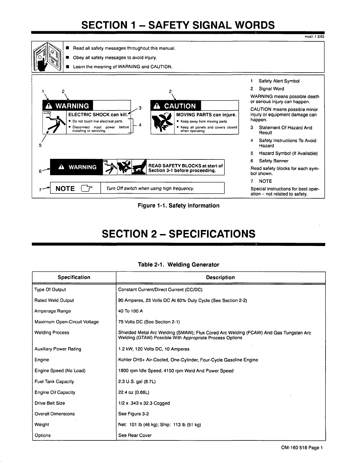
Specification
TypeOfOutput
Rated
Weld
Output
Amperage
Maximum
Welding
Auxiliary
Engine
Engine
Fuel
Engine
Drive
Overall
Weight
Options
Range
Open-Circuit
Process
Power
Speed
Tank
Capacity
Oil
Capacity
Belt
Size
Dimensions
Rating
(No
Load)
Voltage
Constant
90
Amperes,
40
To
Volts
75
Shielded
Welding
1.2
kW,
Kohler
1800
rpm
2.3
U.S.
22.4
oz
.343x32.3
1/2
x
See
Figure
Net:
101
See
Rear
Table
Current/Direct
25
A
100
DC
(See
Metal
Arc
(GTAW)
120
Volts
CH5+
Air-Cooled,
Idle
Speed;
(8.7L)
gal
(0.66L)
3-2
lb
(46
Cover
2-1.
Volts
Section
Welding
Possible
DC,
Cogged
kg);
Welding
Current
DC
At
60%
2-1)
(SMAW);
With
10
Amperes
One-Cylinder,
4150
rpm
113
Ship:
Generator
(CC/DC)
Duty
Cycle
Flux
Appropriate
Four-Cycle
Weld
And
lb
(51
kg)
Description
Section
(See
Cored
Arc
Process
Power
Welding
Options
Gasoline
Speed
2-2)
Engine
(FCAW)
And
Gas
Tungsten
Arc
OM-160
518
Page
1
Page 14

Page 15
2-1.
Volt-Ampere
Curves
Cl)
0
>
0
100
90
80
60
50
40
30
70
20
10
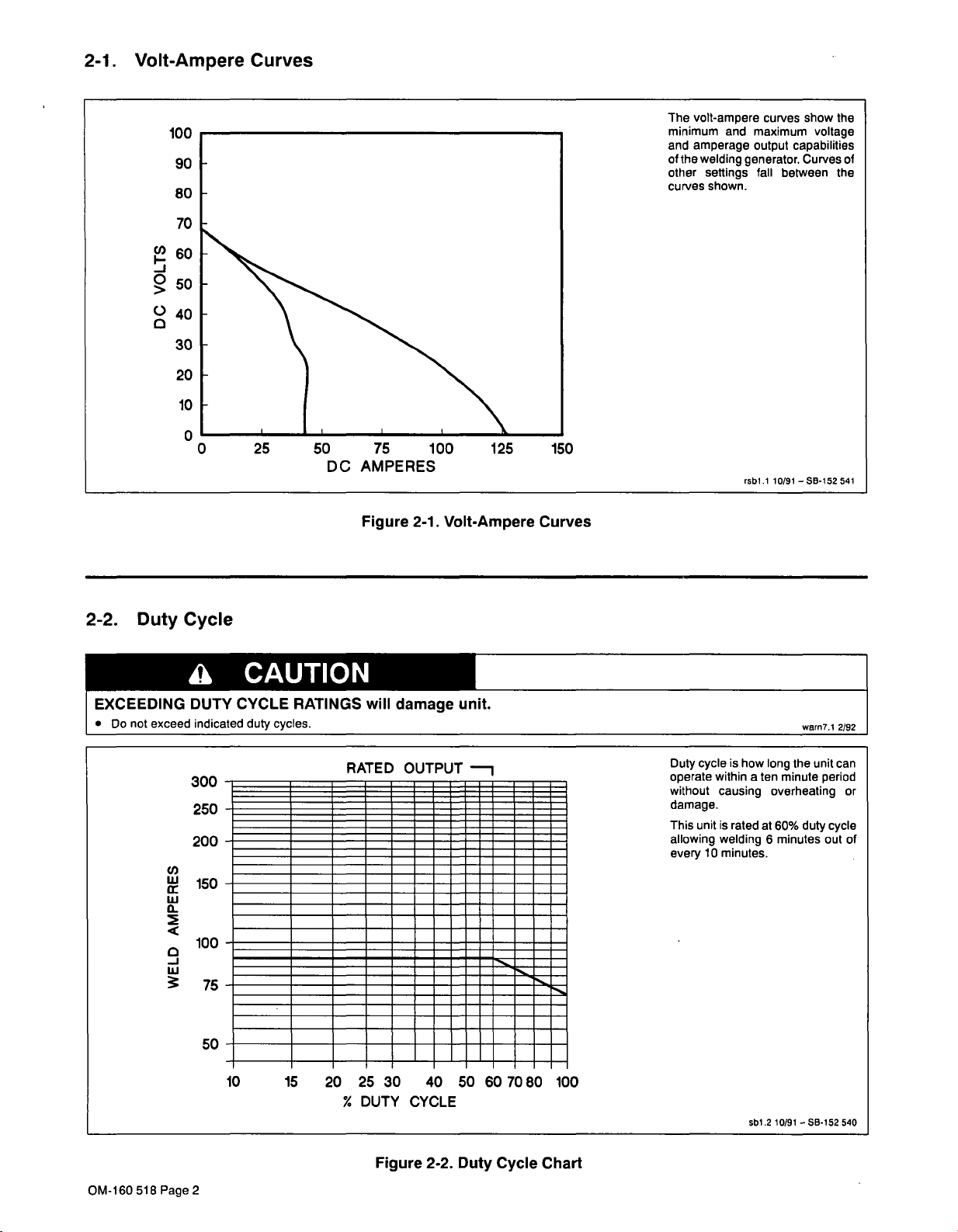
The
volt-ampere
minimum
and
amperage
of
the
welding
other
curves
and
generator.
settings
shown.
maximum
output
fall
curves
capabilities
between
show
voltage
Curves
the
of
the
0
0
25
50
DC
75
AMPERES
Figure
100
2-1.
Volt-Ampere
125
150
Curves
rsDl.1
10/91
SB-152
541
2-2.
EXCEEDING
Do
Duty
not
exceed
U)
w
a
<
Cycle
a
DUTY
indicated
300
250
200
150
100
75
50-
CAUTION
CYCLE
duty
cycles.
-
-
.
.
RATINGS
RATED
will
damage
OUTPUT
---
unit.
~......,
warn7.1
2/92
is
Duty
cycle
operate
without
how
within
causing
ten
a
unit
the
long
minute
period
overheating
can
or
damage.
unit
This
allowing
every
--
is
welding
10
minutes.
rated
at
6
60%
minutes
duty
cycle
out
of
OM-160
518
Page
10
2
15
20
%
25
DUTY
Figure
30
40
CYCLE
2-2.
50
Duty
60
Cycle
7080
100
Chart
sbl.2
10/91
SB-152
540
Page 16

Page 17
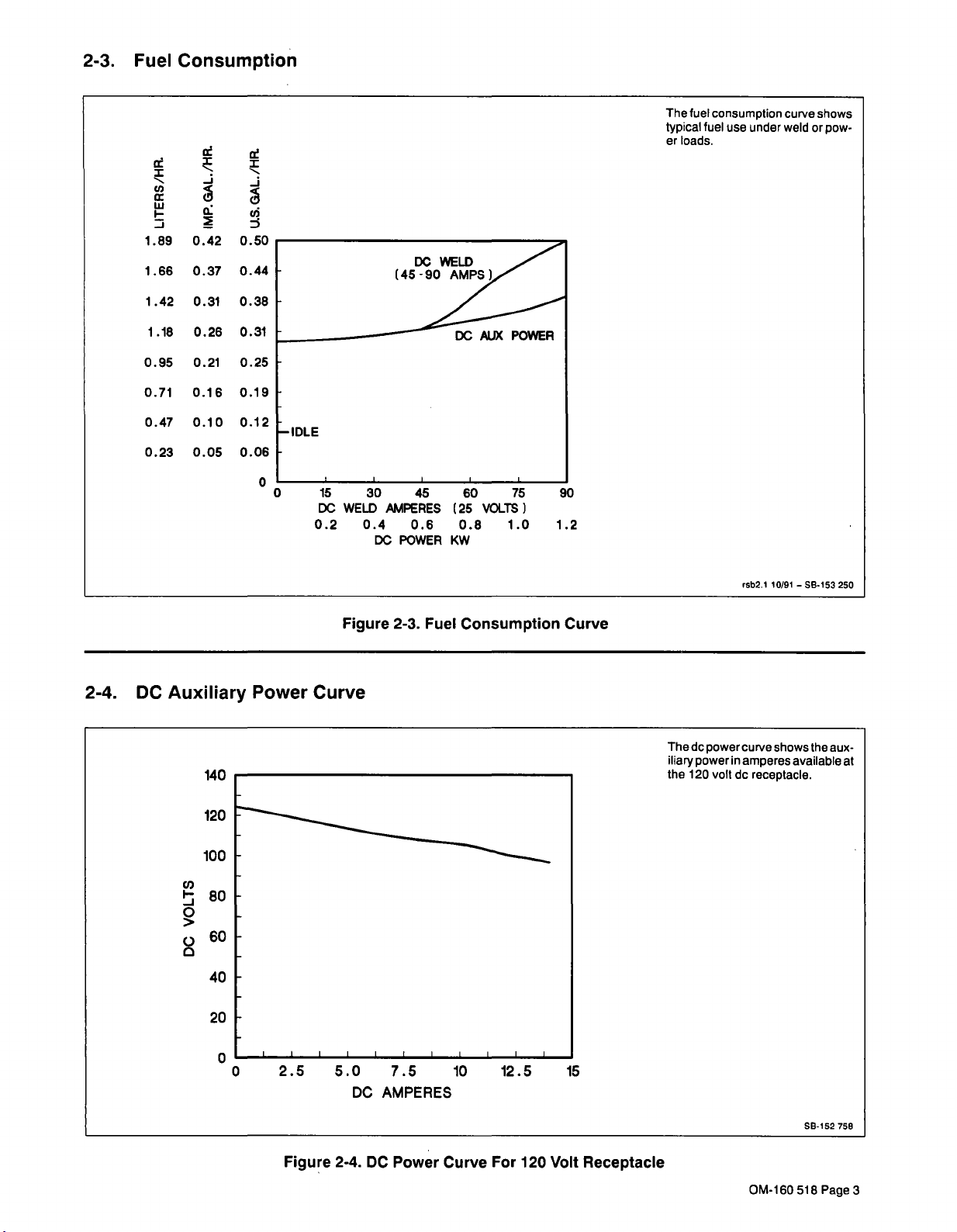
2-3.
Fuel
Consumption
The
fuel
typical
loads.
er
consumption
fuel
under
use
curve
weld
shows
or
pow
~
ci,
w
I-
1.89
1
.66
1.42
1
0.95
0.71
0.47
0.23
.18
-J
Q~
0.42
0.37
0.31
0.26
0.21
0.16
0.10
0.05
_j
ci
0.50
0.44
0.38
0.31
0.25
0.19
0.12
0.06
~
DC
-IDLE
0
0
15
DC
0.2
30
WELD
0.4
DC
Figure
AMPERES
0.6
POWER
2-3.
45
(25
KW
Fuel
60
0.8
Consumption
AUX
VOLTS)
POWER
75
1.0
90
1.2
Curve
rsb2.I
10/91SB-153
250
2-4.
DC
Auxiliary
~80
0
>
Q60
140
40
20
Power
Curve
The
dc
iliary
the
120
power
power
in
volt
shows
curve
amperes
dc
receptacle.
the
aux
available
at
0
0
2.5
5.0
DC
7.5
AMPERES
10
12.5
15
SB.152
758
Figure
2-4.
DC
Power
Curve
For
120
Volt
Receptacle
OM-160
518
Page
3
Page 18

Page 19
SECTION
3INSTALLATION
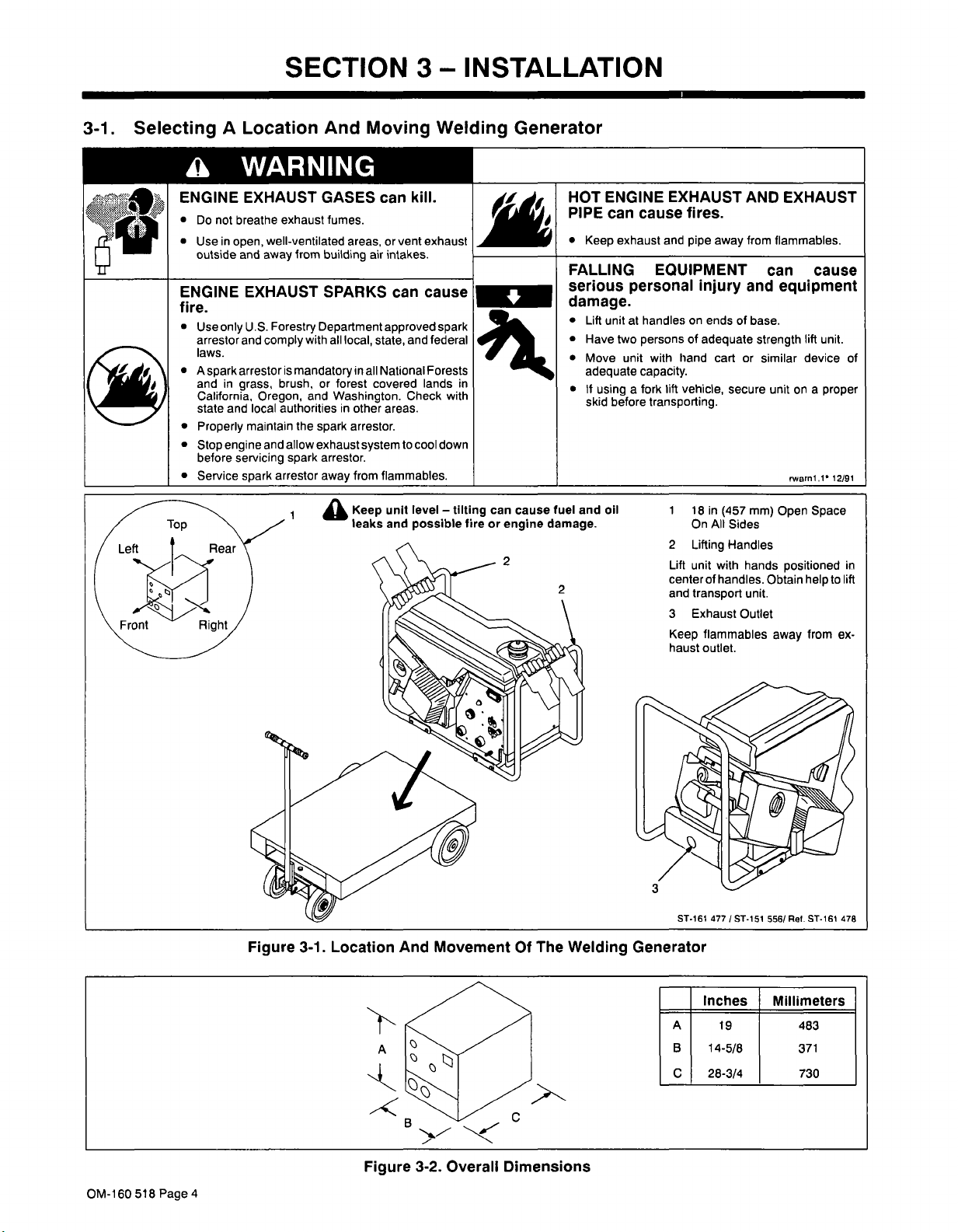
3-1.
Selecting
a
ENGINE
Do
Use
outside
ENGINE
fire.
Use
arrestor
laws.
A
spark
and
California,
state
Properly
Stop
before
Service
A
Location
WARNING
EXHAUST
breathe
not
in
open,
and
EXHAUST
U.S.
only
and
arrestor
in
grass,
Oregon,
and
local
maintain
engine
servicing
spark
And
GASES
exhaust
fumes.
well-ventilated
from
away
Forestry
comply
and
arrestor
building
SPARKS
Department
with
is
mandatory
or
brush,
and
authorities
the
spark
allow
exhaust
arrestor.
spark
away
Moving
can
or
areas,
air
intakes.
local,
in
in
other
arrestor.
system
from
Keep
leaks
approved
state,
all
National
covered
areas.
flammables.
unit
and
all
forest
Washington.
kill.
vent
can
and
Check
to
cool
level
possible
Welding
exhaust
cause
spark
federal
Forests
lands
in
with
down
tilting
fire
Generator
can
cause
or
engine
2
HOT
PIPE
FALLING
serious
damage.
fuel
and
damage.
2
ENGINE
can
exhaust
Keep
Lift
Unit
Have
two
Move
unit
adequate
It
using
before
skid
oil
EXHAUST
cause
fires.
and
EQUIPMENT
personal
handlesonends
at
persons
with
hand
capacity.
lift
fork
a
vehicle,
transporting.
1
2
Lift
centerof
and
3
Keep
haust
pipe
away
injury
of
adequate
cart
secure
in
18
(457
All
On
Sides
Handles
Lifting
unit
with
handles.
transport
Exhaust
flammables
outlet.
AND
from
and
of
base.
strength
similar
or
mm)
hands
unit.
Outlet
EXHAUST
flammables.
can
cause
equipment
lift
unit.
device
unit
a
on
rwarnl.1
Space
Open
positioned
Obtain
help
from
away
proper
12/91
to
ex
of
in
lift
OM-160
518
Page
Figure
3-1.
Location
~<
And
Movement
Of
The
Welding
5T-161
Generator
4771
ST-151
Inches
A
19
B
14-5/8
C
28-3/4
C
5T.161
Ref.
556/
Millimeters
483
371
730
478
>.-.~<
3-2.
Figure
4
Overall
Dimensions
Page 20

Page 21
200
200
Maximum
lubrication.
Keep
tilted.
Do
room
out
Do
let
fuel
leak
not
from
cap
during
tilting.
fuel
cap
overfill
not
for
expansion
causing
tilting
at
leaks.
angles
highest
fuel
tank
nd
a
for
proper
when
point
leave
with
tilting
S-0702
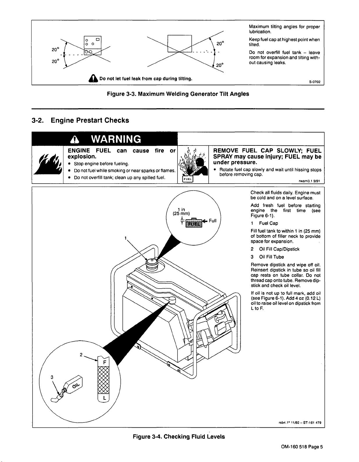
3-2.
.~
Engine
ENGINE
explosion.
Prestart
a
Stop
Do
not
not
Do
Checks
WARNING
FUEL
before
engine
fuel
while
overfill
tank;
Figure
can
fueling.
smoking
clean
3-3.
or
up
cause
near
any
Maximum
sparks
spilled
fire
or
fuel.
flames.
Welding
or
Generator
Tilt
REMOVE
SPRAY
under
Rotate
before
Angles
FUEL
may
pressure.
fuel
cap
removing
CAP
cause
slowly
cap.
Check
be
cold
Add
injury;
and
all
and
fresh
engine
Figure
6-1).
I
Fuel
Fill
fuel
tanktowithin
of
bottomoffiller
for
space
2
Fill
Oil
Fill
Oil
3
Remove
Reinsert
rests
cap
thread
cap
stick
and
If
oil
is
not
(see
Figure
oil
to
raise
F.
L
to
SLOWLY;
FUEL
wait
until
fluids
daily.
level
on
a
fuel
the
Cap
dipstick
dipstick
check
before
first
neck
expansion.
Cap/Dipstick
Tube
and
in
tube
to
up
6-1).
level
tube.
oil
full
Add
collar.
level.
on
on
onto
oil
may
hissing
rwarn3
Engine
surface.
time
in
1
(25
to
wipe
tube
so
Remove
mark,
4
oz
dipstick
FUEL
be
stops
1
9191
must
starting
(see
mm)
provide
off
oil.
fill
oil
Do
not
dip
add
oil
(0.12
L)
from
Figure
3-4.
Checking
Fluid
Levels
rsb4,1
OM-160
11/92ST-16l
518
Page
479
5
Page 22

Page 23
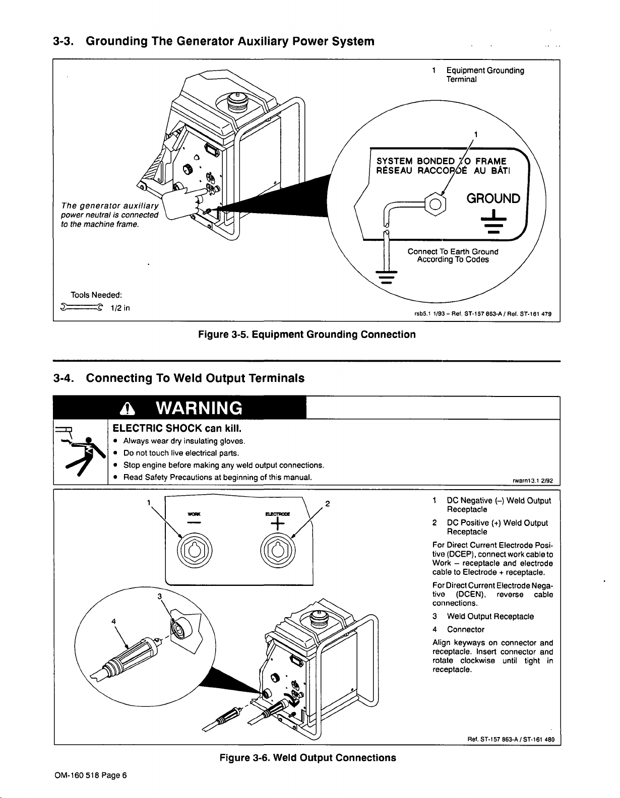
3-3.
Grounding
The
Generator
Auxiliary
Power
System
1
Equipment
Terminal
Grounding
The
power
to
3-4.
.~
generator
neutralisconnected
the
machine
Tools
Needed:
-.~
Connecting
.
auxiliary
frame.
a
ELECTRIC
Always
Do
not
Stop
engine
Read
To
Weld
WARNING
SHOCK
wear
dry
touch
live
before
Precautions
Safety
Figure
Output
can
insulating
electrical
gloves.
parts.
making
at
3-5.
Terminals
kill.
weld
any
beginning
Equipment
connections.
output
of
this
manual.
Grounding
Connection
rsb5.1
1/93
ST-i
Ret.
~7
863-A/Ret.
ST-I
rwarnl3,l
81
479
2/92
OM-160
518
Page
I
DC
1
2
~
Receptacle
2
DC
Negative
Positive
()
(+)
Weld
Weld
Output
Output
Receptacle
For
Direct
Current
~
~
tive
(DCEP).
Work
receptacle
cable
to
Electrode
For
Direct
tive
connections.
3
4
Align
receptacle.
rotate
Current
(DCEN),
Weld
Output
Connector
keyways
clockwise
connect
Receptacle
on
Insert
Electrode
and
+
Electrode
reverse
connector
connector
until
Posi
work
cable
electrode
receptacle.
Nega
cable
and
and
tight
to
in
receptacle.
~-
Ret.
ST-I57863-A/ST-161
Weld
Figure
6
3-6.
Output
Connections
480
Page 24

Page 25

SECTION
4-
OPERATING
THE
WELDING
GENERATOR
a
ELECTRIC
Do
not
Always
Insulate
Stop
Keep
WELDING
Do
not
Watch
Do
not
Do
not
Allow
ARC
NOISE
Wear
Wear
FUMES
Keep
Ventilate
=~!t?
Read
manufacturers
WARNING
SHOCK
touch
live
wear
dry
yourself
before
engine
all
panels
can
weld
near
for
fire;
keep
unit
locate
weldonclosed
and
work
RAYS
can
damage
welding
correct
AND
head
your
area,
Material
can
helmet
eye,
GASES
or
Safety
kill.
can
electrical
insulating
from
work
parts.
gloves.
and
ground.
installingorservicing.
and
covers
securely
cause
equipment
fire
flammable
extinguisher
combustible
over
containers.
to
burn
or
material.
nearby.
cool
eyes
hearing.
with
correct
and
ear,
out
of
the
use
breathing
Data
instructions
body
can
fumes.
Sheets
for
protection
be
device.
material
in
place
explosion.
surfaces.
before
handling.
and
skin;
of
shade
filter.
hazardous.
(MSDS5)
used.
and
!
~
~_.
,~
I
\
E
NGINE
Do
not
in
Use
outside
ENGINE
sion.
Stop
Do
not
Do
not
MOVING
Keep
and
rotors.
Keep
and
securely
MAGNETIC
RENTS
Pacemaker
Wearers
near
See
Safety
sic
welding
EXHAUST
breathe
open,
and
FUEL
engine
fuel
overfill
PARTS
away
all
doors,
can
should
welding
any
Precautions
safety
exhaust
well-ventilated
from
away
can
before
fueling.
while
smoking
clean
tank;
can
from
moving
panels,
in
place.
FIELDS
affect
pacemaker
wearers
keep
consult
operations.
at
information.
GASES
fumes.
areas,
building
any
cause
or
near
up
any
cause
such
parts
and
covers,
FROM
away.
their
doctor
beginning
kill.
can
vent
or
air
intakes.
fire
or
or
sparks
fuel.
spilled
injury.
as
fans,
guards
HIGH
operation.
before
of
manual
~
exhaust
explo
flames.
belts.
closed
CUR
going
for
ba
110/91
4
2
U
Figure
_______
1
Amperage
2
Engine
Low
3
4
Throttle
5
6
4-1.
Controls
3
_______
~LE~1
______
4
Choke
6
Fuel
1
Insulating
2
Safety
Shields
3
Welding
4
Hand
Wear
dry
glasses
welding
correct
a
Control
Hour
Oil
Level
Control
Control
Shutoff
Valve
ST-161
Gloves
Glasses
Helmet
Shield
insulating
with
side
helmet
or
shadeoffilter
Z49.1).
Meter
(Optional)
(Optional)
Light
Lever
477/Rel.ST-161
With
gloves,
shields,
shield
hand
(see
Side
safety
and
with
ANSI
sb3.110/91
479
a
Figure
4-2.
Safety
Equipment
OM-160
518
Page
7
Page 26

Page 27

Figure
4-3.
Work
Tools
Clamp
Needed:
1
Work
Clamp
Connect
work
paint-free
close
as
Use
clean
chipping
after
to
wire
metal
hammer
welding.
clamp
location
weld
brush
weld
at
on
area as
or
sandpaper
joint
to
to
a
clean,
workpiece,
possible.
area.
remove
sb4.1
to
Use
slag
2/93
Figure
4-4.
Amperage
3
Control
1
2
1
Amperage
Use
control
Engine
age.
weld/power
weld
output.
while
justed
2
Electrode
Scale
shows
trode
diameter
3
Amperage
Numbers
amperes.
Control
select
to
must
speed
Control
welding.
Scale
recommended
for
Scale
scale
in
weld
weld
be
running
to
may
amperage.
are
Ret.
amper
attain
be
welding
ST-157
at
full
ad
elec
883-A
OM-160
518
Page
1
Open
Close
or
2
Use
and
engine,
3
Use
air/fuel
to
engine.Ifstarting
move
4
Pull
smooth
After
levertoleft.
Keep
auxiliary
for
Stop
4-5.
Figure
8
Engine
Controls
Fuel
valve
valve
during
Throttle
lever
select
Choke
lever
right
choke
Starter
starter
engine
throttle
idle
speed.
unit
Shutoff
before
when
transport.
Control
to
start
engine
levertoRun.
move
Control
to
regulate
mixture.
on)
(choke
levertoleft
Handle
handle
motion.
warms,
lever
power.
by
moving
S-0690
Valve
starting
unit
Lever
and
speed.
Lever
Move
if
starting
a
warm
move
in
Run
Move
lever
Ret.
/
engine.
is
in
not
stop
engine
To
carburetor
choke
a
engine,
(choke
with
quick,
choke
for
lever
to
to
ST-161
use
start
lever
cold
off).
weld/
Idle
Stop.
478
Page 28

Page 29

6
1
Use
hours
erates
Engine
meter
(see
only
Hour
check
to
Section
when
Meter
total
This
6).
engine
operating
meter
op
is
running.
rsb6.1
2/92
Figure
Install
&
Connect
EquIpment~)
)
________________
_____
)
________________
_____
Insert
Electrode
Into_Holder
Select
Electrode
Begin
_________________
Figure
4-6.
Engine
Hour
1
Q~
LOW
4-7.
_____ _____
Weldin~
OIL
Automatic
Put
Personal
Equipment
On
Safety
Low
I
~~JJ
I
Meter
(Optional)
Shutdown
ControI~~)
(Optional)
Start
________________
_____
Oil
Set
Low
I
flickers
Light
pulled
automatic
Engine
is
added
oil
Fill
engine
stick
(see
Eng~~Uia~)__..)
Oil
Level
when
if
does
engine
low
not
to
with
has
oil
engine.
oil
Figure
~g~pmen~,~
Light
starter
stopped
level
start
F
to
3-4).
handle
shutdown.
until
sufficient
mark
Ref.
ST-157
rSbO.1
due
on
is
to
dip
863
~-
9/92
Figure
4-8.
Sequence
Of
Shielded
Metal
Arc
Welding
(SMAW)
OM-160
518
Page
9
Page 30

Page 31

SECTION
5-
OPERATING
AUXILIARY
EQUIPMENT
5-1.
a
ELECTRIC
Do
Stop
reconnection.
Ground
national,
Connect
earth
Do
normally
ELECTRIC
If
using
disconnect
electrode
hazards.
Watch
Keep
use
The
weld
when
the
Auxiliary
WARNING
SHOCK
touch
not
engine
generator
state,
equipment
ground.
not
connect
supplied
SPARKS
auxiliary
both
from
fire.
for
fire
a
extinguisher
it.
output
engine
Power
live
electrical
before
and
to
any
by
welding
causing
terminals
is
running.
DC
making
according
local
grounding
power
kill.
can
parts.
internal
inspection
all
to
codes.
terminal
electrical
utility
distribution
power.
can
cause
and
only
cables
electric
and
nearby,
are
electrically
to
shock
not
know
Receptacle
applicable
to
a
proper
system
fire.
welding,
prevent
and
how
energized
or
live
fire
to
,~-.
X
~
~
cii
0
MOVING
injury.
Keep
away
and
rotors.
DC
electrical
incorrect
Essentially
motors.
duty
speed
This
auxiliary
lights
AC/DC
power
all
Keep
and
securely
AUXILIARY
DC
Use
rated
tools
Do
not
use
equipment,
However,
tools
may
tools
unit
provides
power.
and
portable
DC
or
AC-only
any
PARTS
from
moving
doors,
panels,
in
place.
POWER
equipment
operation.
only
output
for
DC.
DC
to
power
induction
or
all
hand
tools
the
damaged
run
only
1200
DC
power
power
rated
switches
This
be
will
ratings.
can
cause
such
parts
covers,
for
incandescent
AC
motors,
motors.
are
powered
on
DC
by
full
at
speed
of
watts
is
suitable
with
tools
must
power
equipment.
serious
as
fans,
belts,
and
can
and
inexpensive/light
power,
on
direct
for
115or120
closed
guards
damage
cause
lights
transformer
universal
by
and
variable
DC.
current
incandescent
be
used
not
rwarn8.1
and
(DC)
volt
10/92
to
Figure
5-1.
Auxiliary
Power
DC
Receptacle
1
120V
Maximum
1.2
kW.
able
only
DC
power
cent
lights
tools
with
DC
ratings.
2
pensive/light
damaged
able
speed
speed
Use
DC
cent
lights
Do
not
AC-only
transformer
tors,
duction
2
lOAFuseFi
Fl
protects
load
or
tacle.IfFl
continues
at
put
is
still
available.
fuse
replacement.
And
Circuit
Protection
1OA
output
Full
auxiliary
when
is
suitable
and
115
The
DC
by
tools
DC.
on
output
and
DC
use
rated
motors.
generator
circuits
short
opens,
to
run
the
receptacle.
DC
Receptacle
RUN
at
power
not
welding.
for
incandes
portable
120
volt
or
duty
only
tools
AC/DC
switchesoninex
tools
power,
will
run
only
for
incandes
rated
to
power
equipment,
equipment,
from
dc
on
the
generator
but
there
Weld
See
Section
Ret.
ST.157
speed
is
avail
power
may
and
at
for
run
AC
recep
is
no
output
6-7
vari
or
over
863-A
full
DC.
any
mo
out
is
or
be
in
for
5-2.
OM-160
Auxiliary
)
518
Page
10
Equipment
)
Figure
Operation
OnA
lnstat&Co~n~ct~)
5-2.
SequenceOfAuxiliary
)Turn
Equipment
liarY))
Operation
Begin
Ope~on
Page 32

Page 33

SECTION
6
MAINTENANCE
&
TROUBLESHOOTING
6-1.
The
Routine
maintenance
a
ELECTRIC
Do
not
Always
Insulate
Stop
engine
Keep
ENGINE
Do
not
in
Use
outside
Maintenance
label
WARNING
SHOCK
touch
live
wear
dry
from
yourself
before
all
breathe
open,
panels
EXHAUST
well-ventilated
and
away
is
located
and
exhaust
can
electrical
insulating
parts.
gloves.
work
installing
covers
GASES
fumes.
from
any
the
on
kill.
and
ground.
or
servicing.
securely
can
or
areas,
building
fuel
in
vent
air
tank
place.
kill.
exhaust
intakes.
above
the
throttle
ENGINE
sion.
MOVING
HOT
Maintenance
sons.
control
FUEL
Stop
engine
Do
fuel
not
while
Do
overfill
not
PARTS
hands,
Keep
parts
moving
tors.
all
Keep
and
doors,
securelyinplace.
PARTS
Allow
cooling
Wear
protective
hot
on
a
engine.
to
lever
(see
can
before
smoking
tank;
loose
such
panels,
can
period
gloves
be
performed
Figure
cause
fueling.
or
clean
up
can
cause
clothing,
as
pulleys,
covers,
cause
before
and
6-3).
fire
or
explo
near
any
sparks
spilled
flames.
or
fuel
injury.
and
tools
away
belts,
guards
burns.
when
rwarn9.I
and
closed
working
fans,
and
severe
servicing.
clothing
onlybyqualified
from
ro
per
10/91
Recommended
Check
Oil
Oil
~
.2
~5
STOP
Oil-API
Below
Above
oil
daily
Capacity
Change
Air
Filter
Air
filter
Engine
32F
32F
Service
element
RPM
~
(4
Service
(0C)
(0C)
Add
oz.
22.4
Normal
100
.
... .
Classification
SAE
5W-20,
SAE
1OW-30,
to
Full
oz.
(0.66L)
conditions
hours
or
Kohler
1506306
Miller
067101
-
IDLE
1800
RUN
(Weld&Power)
~
SF-SG/CC-CD
SAE
SAE
on
dipstick)
100
less-See
Figure
5W-30
1OW-40
hours
Manual
-
6-1.
4150
4
R~J
Maintenance
Drive
Drive
Spark
Spark
*Resistor
Fuel
Capacity
Fuel
grade
least
at
If
equipped
service
L$~
Label
Belt
Belt
plug
Plug
Spark
87
per
Inspection
Resistor
gap
Plug
U.S.
2.3
Regular
octane
with
spark
Manual
KOHLER
SPEED
100
Miller
&
Std
Champion
Mandatory
Gal
Unleaded
or
+
(RON
arrestor,
or
supplied
CH5+
CONTROL
hours
150412
.030
RCI2YC*
in
(8.7L)
MON)
inspect
instructions.
ENGiNE
See
in.
Canada
Vented
2
(.76
and
S.146
Manual
mm)
cap
281-A
OM-160
518
Page
11
Page 34

Page 35

Stop
engine
before
maintaining.
not
throw
take
25
~-
Do
fluids
center.
~JJ
~y~
6-4~J
away
to
area
Hours
engine
recycling
Air
Clean
Cleaner
Foam
Element
Hours
500
ED
Check
Valve
hours
Clearance
havealferna
slip
rings,
FactoryAu
by
Station.
oil
bear
shut
engInes
manual
Every200
for
brushes,
and
ings
down
thorized
optional/ow
checked
Service
6-2.
Changing
Engine
Oil
Figure
6-2.
Maintenance
Tools
Schedule
Needed:
3/8
Stop
Change
in
gine
1
Use
room
2
Remove
draining
3
Remove
for
plug.
4
Fill
mark
and
in
specifications.
Reinstall
engine.
engine
Figure
is
still
Support
blocks
for
oil
Fill
Oil
oil.
Drain
Oil
oiltodrain
Maintenance
crankcase
on
dipstick.
grade
oil
Change
warm.
Block
large
pan.
at
enough
6-1.
Cap/Dipstick
fill
oil
cap/dipstick
Plug
Allow
plug.
completely.
Label
with
new
Use
of
oil.
See
fill
oil
cap/dipstick.
interval
while
oil
to
enough
Reinstall
oil
correct
Figure
ST-I
listed
en
provide
before
time
F
to
type
6-1
for
61
481
OM-160
518
Page
Figure
12
6-3.
Changing
Engine
Oil
Page 36

Page 37

6-3.
Adjusting
Engine
Speed
Moving
Have
before
Parts
belt
guard
running
Hazard.
in
place
engine.
READ
Section
SAFETY
before
6
Tools
BLOCKS
Needed:
~
at
proceeding.
and
Start
1
Move
2
3
Loosen
adjustment
engine
screws.
4
If
stop
(see
5
Turn
two
and
control
plate
speed
securing
3/8,
Throttle
levertoRun.
Speed
Securing
Belt
engine
engine
Section
Speed
screw
full
start
lever
left
(see
9/32
run
Control
Adjustment
securing
plate
runs
Guard
does
and
Adjustment
out
turns.
engine.
and
or
items
screws
in
start
of
load.
at
screws
4150
remove
Lever
right
rpm.
reach
no
Plate
and
move
left
or
Tighten
4150rpm,
belt
guard
engine
Screw
at
not
6-6).
Screw
(counterclockwise)
Reinstall
right
Move
speed
to
2
and
and
belt
guard
throttle
adjustment
engine
adjust
3).
Tighten
stop
engine.
ST-161
Ref.
until
482
6-4.
Air
Cleaner
2
Service
3
Figure
4
Figure
6-4.
6-5.
Engine
Air
Cleaner
Speed
Adjustment
READ
Section6before
Maintenance
SAFETY
BLOCKS
at
proceeding.
Stop
engine.
Air
1
2
Retaining
Loosen
air
move
3
Wing
Remove
4
Foam
Wash
element
detergent.
element
Saturate
oil.
gine
Reinstall
element.
5
Paper
Replace
with
a
new
element
dirty
pressed
Reinstall
start
Cleaner
Screw
retaining
cleaner
Nut
shown.
as
Element
in
Rinse
and
allow
element
Squeeze
element
Element
or
dirty
element.
or
air.
air
cleaner
OM-160
of
Cover
screw
cover.
(Precleaner)
water
warm
all
detergent
to
air-dry.
with
clean
out
excess
on
damaged
clean
Do
cover.
518
not
with
5T-151
and
with
from
en
paper
element
wash
com
Page
re
oil.
839
13
Page 38

Page 39

6-5.
Clean
Air
Intake
And
Cooling
Figure
6-6.
Areas
Air
Intake
And
Cooling
Areas
6-6.
Stop
1
Remove
Remove
2
Readjust
cracked
3
Drive
Tools
Needed:
~
9/16,5/8
engine.
Guard
Belt
five
screws
guard
Drive
Belt
belt
tension
belt.
Tensioning
Belt
Adjustment
in
in
7/16
securing
and
inspect
if
necessary.
Screw
I
belt.
~
belt
Replace
guard.
And
Replacement
4
Securing
To
replace
and
loosen
Install
screws.
Check
between
pressure
to
sure
belt,
securing
belt
new
Reinstall
belt
tension
pulleys.
to
a
used
a
Screw
remove
and
tensioning
by
Apply
belt
new
belt.
READ
Section
tensioning
screw,
pressing
about
lb
5.5
or
When
Remove
belt
lb
8.5
(2.5
properly
screws.
hand-tighten
SAFETY
screw
belt.
securing
midway
kg)
(3.9
kg)
pres-
ten-
before
6
sioned,
BLOCKS
proceeding.
belt
deflects
at
inward
start
about
of
Ref.
ST-161
1/8
482
in
(3
mm).
Adjust
screw
obtained.
Reinstall
unit.
Stop
in
or
belt
Remove
out
until
guard
and
belt
by
proper
run
guard
turning
belt
unit
ten
and
tensioning
tension
is
minutes.
readjust
tension
belt
belttensionifnecessary.Replacebeltguard.
OM-160
518
Page
Drive
Figure
14
6-7.
Belt
Adjustment
and
Replacement
Page 40

Page 41

6-7.
Overload
Protection
a
~
120V
WARNING
CAUTION
TOOLS
NOT
USE
CONSULT
1OA
AND
:DC
AC
OWNERS
LIGHTS
ONLY
DC
POWER
ONLY!DO
RATED
MANUAL!
FOR
TOOLS.
10
0
-~-
Fl
READ
Section
Replacement
or
greater,
10
fuse
amperes
A
SAFETY
6
rating:
maximum.
before
volts
125
BLOCKS
at
proceeding.
Stop
engine.
1
Fuse
2
lOAFuseFl
Fuse
Fl
overload
120V
dc
the
engine
there
is
Weld
output
Turn
fuse
to
remove
fuse
holder.
and
panel
If
fuse
Factory
tion.
start
Holder
protects
short
or
receptacle.
continues
no
output
still
is
holder
counterclockwise
fuse.
Push
clockwise
turn
continues
Authorized
of
the
circuit
If
Fl
to
the
at
receptacle.
available.
Put
new
fuse
holder
to
open,
Service
unit
to
from
on
is
open
run
fuse
into
secure.
contact
Sta
the
but
In
Figure
6-8.
Location
OfFlFuse
Ret,
ST-151
~86/Ret.
ST-157
883-A
OM-160
518
Page
15
Page 42

Page 43

6-8.
Troubleshooting
Do
not
Always
Insulate
Stop
engine
Keep
Do
not
in
Use
outside
PARTS
Allow
Wear
hot
on
a
power
WARNING
SHOCK
touch
live
wear
yourself
all
breathe
open,
and
cooling
protective
dry
from
before
and
panels
EXHAUST
exhaust
well-ventilated
away
can
period
gloves
engine.
output.
insulating
kill.
can
electrical
parts.
gloves.
work
and
ground.
installingorservicing.
severe
can
in
vent
or
air
when
from
cause
covers
GASES
before
securely
fumes.
areas,
building
any
servicing.
and
clothing
Table
-~
Have
brushes
Broken
place
kill.
exhaust
intakes.
burns.
working
6-1.
Factory
and
drive
Welding
Authorized
slip
rings.
belt.
Trouble
Remedy
Service
ENGINE
FUEL
sion.
Stop
Do
Do
MOVING
Keep
and
Keep
and
not
not
engine
fuel
while
overfill
PARTS
away
rotors.
all
doors,
securely
before
from
Troubleshooting
persons.
Station
check
can
fueling.
smoking
clean
tank;
can
moving
panels,
in
place.
be
to
performed
generator
cause
or
up
cause
parts
covers,
---~
-..
near
any
such
fire
sparks
spilled
injury.
as
and
guards
only
rwarnhl.1
Section
or
explo
or
fuel.
fans,
by
qualified
--
6-6
flames.
belts,
closed
11/91
AA
ELECTRIC
ENGINE
HOT
Trouble
No
weld
or
auxiliary
Low
Low
Erratic
weld
or
high
welding
output.
weld
arc.
output.
-~
Have
Check
er
(see
Check
Check
Have
Factory
and
adjust
engine
weld
cable
internal
Factory
Authorized
engine
manual).
size
and
external
Authorized
Service
speed.
and
Service
Station
Tune-up
length.
weld
output
Station
check
generator.
forfull
engine
connections.
check
brushes
horsepow
and
slip
-~
-~
--
-~
-a
6.3
rings.
horse
--
-~
-~
-a
-a
-~
---
6-6
6-3
--
--
6-3
--
Check
Check
Check
power
Check
Change
Check
Check
Amperage
drive
belt
and
adjust
(see
engine
governor
to
proper
and
adjust
governor
control
tension.
engine
manual).
(see
engine
electrode
engine
(see
engine
settings
speed.
manual).
polarity.
speed.
manual).
connections.
and
Tune
up
engine
for
full
Weld
OM-160
output
518
Page
uncontrollable.
16
-~
Have
control.
Factory
Authorized
Service
Station
check
Amperage
-~
Page 44

Page 45

Table
6-2.
Auxiliary
Power
Trouble
No
auxiliary
Erratic
Low
auxiliary
Trouble
power.
auxiliary
power.
power.
Remedy
-~
Check
Have
and
replace
Factory
fuse
Authorized
Fl.
Service
Station
check
brushes
and
Slip
-~
-~
Section
6-7
-
rings.
Have
Factory
Authorized
Service
Station
check
brushes
and
slip
--a
--
rings.
Check
drive
belt
and
Check
horsepower
throttle
Move
and
Check
necessary
Check
drive
Have
Factory
adjust
(see
lever
adjust
to
achieve
belt
Authorized
tension.
engine
engine
Run
to
engine
full
tension.
speed.
Tune-up
manual).
position.
Perform
speed.
horsepower
Service
Station
(see
engine
engine
engine
check
to
achieve
maintenance
manual).
generator.
full
as
-~
-~
6-6
6-3
Engine
Engine
will
runs
not
rough
Trouble
start.
or
stalls.
6-3.
Table
fuel
Open
oil
Check
fuel
Check
throttle
Move
See
engine
--
Dirt
Have
water
or
Factory
Tune-up
shutoff
level.
level
control
manual.
in
Authorized
engine
Engine
Check
in
fuet.
(see
valve.
optional
tank.
levertoRun
Replace
engine
Trouble
Remedy
oil
fuel.
Service
manual).
shutdown
level
position.
Station
check
switch.
fuel
filter.
Section
---~
-..
--~
--~
---
Figure
Figure
Figure
Figure
Figure
4-5
3-4,
4-7
3-4
4-5
OM-160
518
Page
17
Page 46

Page 47

U)
m
C)
0
z
m
r
-I
m
C)
a
r
a
C)
Cl)
WELD
POSITIVE
OUTPUT
DC
NEGATIVE
(POS)
25
RC2
539-A
7
B
POWER
15-I25VDC
AUX
I
58-152
PLG3/RC3
Generator
Welding
For
PLG2
IIRC2
1161
1/1/ti
11
kJltlJdl2hl
1~
13312
17
16
15
PLG2/RC2
I
41ttP/PtttPLG2
123456789
313
_~jA-_~-~_-~46
I
RC3
I
I
23456789
ttl\ttttttPLc3
1/31331351391241
1
~4)4
>1>
PLG3/RC3
E!~i~IIj
>2>
PLG3/RC3
METER
RUNNING
(OPTIONAL)
HOUR
rJJ3
-a
I
ENG
GNO
OIL
LEVEL
Diagram
Circuit
7-1.
Figure
-
TAB
ENGINE
EXCITATION
0
-u
0)
0
0)
C,
0,
I,
CD
(0
IGNITION
KILL
OIL
SHUTOOWN
LOW
I
L
Page 48

Page 49

SP4
860-B
ST-153
Generator
-,
ALTERNATOR
HOUSING
I
I
Welding
For
Diagram
OUTPUT
NEGATIVE
Wiring
7-2.
Figure
~
BLK
r(~~
I
silo
GR~W
L
r
L
Page 50

Page 51

SECTION
8-
WELDING
METHODS
&
TROUBLESHOOTING
mcd5.~
9192
a
ELECTRIC
Always
Insulate
Do
not
Keep
FUMES
to
your
Keep
Ventilate
Read
manufacturers
WELDING
Do
not
Watch
Do
not
Do
not
Allow
ARC
NOISE
Wear
Wear
WARNING
SHOCK
wear
dry
yourself
touch
live
all
panels
AND
GASES
health.
head
your
or
area,
Material
can
weld
near
for
fire;
keep
unit
locate
weldonclosed
work
and
RAYS
can
damage
welding
correct
can
helmet
eye,
can
insulating
from
work
electrical
and
covers
of
the
out
use
breathing
Data
Safety
instructions
cause
flammable
extinguisher
combustible
over
containers.
equipment
burn
hearing.
with
and
ear,
kill.
gloves.
and
parts.
securely
can
fumes.
Sheets
for
fire
material.
to
cool
eyes
correct
body
ground.
in
be
hazardous
device.
(MSDSs)
material
or
used.
explosion.
nearby.
surfaces.
before
and
shade
protection.
and
handling
skin;
of
filter.
4
MOVING
Keep
and
rotors.
Keep
and
securely
HOT
PARTS
Allow
Wear
MAGNETIC
RENTS
Pacemaker
Wearers
near
arc
tions.
WELDING
tronic
Disconnect
vehicle.
Place
See
Safety
welding
PARTS
from
away
all
doors,
in
can
period
cooling
protective
FIELDS
affect
can
wearers
should
welding,
CURRENT
in
parts
both
work
clamp
Rules
information.
safety
can
moving
panels,
place.
cause
before
gloves
pacemaker
keep
consult
gouging,
vehicles.
battery
close
as
at
beginning
cause
parts
covers,
touching
and
clothing.
FROM
away.
their
or
can
cables
to
such
and
severe
doctor
spot
damage
before
the
of
weld
manual
injury.
as
fans,
belts,
closed
guards
burns.
welded
metal.
HIGH
CUR
operation.
before
opera
elec
welding
as
possible.
for
going
basic
welding
a
on
8-1.
Tools
Shielded
N
OTE
Needed:
~
Metal
2
Arc
Welding
7
Welding
current
4
~
(SMAW)
starts
soon
as
electrode
as
touches
the
workpiece.
1
Workpiece
Make
fore
welding.
2
Work
Place
ble.
3
Electrode
A
small
quires
Follow
one.
electrode
ting
Figure
4
Insulated
5
Electrode
6
Arc
Arc
length
electrode
with
arc
a
sharp,
7
Slag
Use
a
brush
and
slag
making
sure
workpiece
Clamp
close
as
diameter
less
current
recommendations
manufacturer
weld
8-2).
Length
is
the
to
the
correct
crackling
chipping
to
remove
check
another
is
the
weld
to
electrode
than
amperage
Electrode
Holder
Position
distance
workpiece.
amperage
sound.
hammer
slag.
weld
bead
weld
pass.
clean
as
a
when
Holder
from
A
will
and
Remove
ST-151
be
possi
large
set
(see
the
short
give
wire
before
593
re
of
OM-160
518
Page
Shielded
Figure
20
8-1.
Metal
Arc
Welding
(SMAW)
Procedure
Page 52

Page 53

6010
&
6011
w
w
a
0
w
It
I
w
0
w
-J
w
a
-~L
5/32
o
0
Lt)
0
o
U)
I-
-
ow
uJz
0
0
0
0
0
0
LI)
0
ClJ
C\i
C~ C~
LI)
0
0
LI)
~
6013
7014
7018
7024
Ni-Cl
308L
5/32
9115
7,93
1/4
3/32
115
3/IS
7193
1/8
5/32
1115
1132
1/4
5/32
I/IA
I
3132
3/16
~1/8
5/32
M
6010
6011
6013
7014
7018
7024
NI-CL
308L
*EP
EN
uJ
a
0
I
0
w
-J
w
EP
EP
E~EN
EP,EN
ER
EP,EN
ER
ER
=
ELECTRODE
=
ELECTRODE
U
z
0
I
C,)
0
0~
ALL
ALL
ALL
ALL
ALL
FLAT
HORIZ
FILLET
ALL
ALL
POSITIVE
NEGATIVE
2
0
It
I
w
2
uJ
0~
DEEP
DEEP
LOW
MED
LOW
LOW
LOW
LOW
(REVERSE
(STRAIGHT
MIN.
HIGH
SMOOTH,
LOW
SMOOTH,
CAST
STAINLESS
PREP,
SPATTER
GENERAL
FAST
HYDROGEN,
STRONG
FASTER
IRON
POLARITY)
POLARITY)
ROUGH
EASY,
EASY,
-
Ref.
S-087
985-A
0
a
v
v
y
v
/
v
/
Figure
8-2.
Electrode
And
Amperage
Selection
Chart
OM-160
518
Page
21
Page 54

Page 55

1
Electrode
2
Workpiece
3
Arc
electrode
2
Drag
like
striking
after
slightly
out
goes
If
high.
use
piece,
a
match;
touching
electrode
electrode
a
quick
across
lift
work.
was
sticks
twist
workpiece
electrode
If
arc
lifted
to
work-
to
it.
to
free
S-0049
Figure
Figure
8-3.
Ii
8-4.
Striking
Striking
An
Arc
An
3
Arc
Scratch
2
Tapping
Start
Technique
Technique
1
Electrode
2
Workpiece
3
Arc
electrode
Bring
workpiece;
If
arc.
arc
lifted
too
workpiece,
the
high.
electrode.
then
goes
use
straight
lift
slightly
electrode
out,
If
electrode
a
quick
twist
down
to
sticks
to
to
start
was
to
free
S.0050
OM-160
End
518
View
Page
0
1O0~3O0
\
300
10~\~
~-
<~
View
Of
Of
Work
22
Angle
GROOVE
Side
WELDS
Electrode
Figure
Angle
8-5.
Positioning
End
Electrode
ViewOfWork
Holder
Angle
FILLET
Side
WELDS
View
~-
Of
Electrode
Angle
S-0660
Page 56

Page 57

POOR
WELD
BEAD
34~
1
2
3
4
5
Large
Spatter
Rough,
Crater
Slight
Welding
Bad
Overlap
Poor
Penetration
uneven
Deposits
bead
During
NOTE
______________________
Angle
Too
~
Small
WELD
GOOD
Figure
Weld
bead
thicknessofbase
8-6.
shape
BEAD
4
Weld
Bead
Characteristics
affectedbyelectrode
is
metal.
Correct
Angle
5
5
angle,
arc
1
Fine
Uniform
2
Moderate
3
Welding
Weld
a
new
in
1/8
(3.2
welded.
being
No
4
Overlap
Good
5
Metal
length,
Spatter
Bead
Crater
bead
thickness
mm)
Penetration
travel
Too
Angle
During
or
layer
Into
speed,
Large
S-0053.A
for
in
Base
S-0052-B
and
each
metals
Too
H
Li
Short
Slow
Figure
8-7.
ELECTRODE
Conditions
Drag
ARC
TRAVEL
That
ANGLE
L_]
Normal
LENGTH
Normal
SPEED
Affect
Weld
Bead
Shape
Too
Long
Fast
OM160
Spatter
518
S-066
Page
1
23
Page 58

Page 59

NOTE
~
Normally,
however,
multiple
stringer
a
single
for
wide
stringer
groove
beads
work
bead
is
satisfactory
weld
jointsorbridging
better.
for
most
across
narrow
gaps,
groove
a
weave
weld
joints;
bead
or
1
Stringer
Movement
2
Weave
Movement
3
Weave
Use
weave
wide
area
trode.
Do
ceed
https://manualmachine.com/3
Ele
Figure
I
8-8.
ctrode
L
Mov
/
$~
~
~
~~I~f
4jI~t~-
ement
2
/
During
Welding
/
2-1/2
electrode.
1
Tack
Prevent
edges
ing
together
tack
welding
tior,
before
2
Square
Good
for
thick.
(5
mm)
3
Single
Good
for
in
3/4
(5-19
with
oxyacetylene
equipment.
ting
from
material
alsobeused
ercan
els.
Create
30
materials
4
Double
Good
for
3/l6in(5mm).
Bead
Along
Bead
Along
Patterns
patterns
in
one
let
not
times
Welds
ahead
the
final
Groove
materials
V-Groove
materials
mm)
after
degree
in
V-groove
V-Groove
materials
Steady
Seam
SideToSide
Seam
to
of
pass
weave
diameter
of
joint
of
electrode
materials
weld.
Weld
up
Weld
3/16
thick.
or
plasma
Remove
cutting.
to
prepare
angle
welding.
thicker
the
width
from
to
Cut
of
Weld
cover
elec
ex
S-0054A
draw
in
posi
3/16
through
bevel
cut
scale
A
grind
bev
bevel
than
9-0662
a
of
by
in
on
2To3in
(51-76
(6.4
OM-160
1/4in
mm4
mm)
518
~
Page
0
24
I
4..
8-9.
Butt
Weld
Joints
Test
1
Vise
2
Weld
Joint
Hammer
3
weld
joint
bends
in
direction
over
shown.
but
S-0057-B
does
Strike
weld
A
good
not
break.
1
Figure
2
1
Figure
8-10.
Page 60

Page 61

1
Electrode
2
Fillet
arc
Keep
rate
of
speed.
shown
corner.
surface.
For
maximum
sides
of
3
Multi-Layer
Weld
second
a
fillet
er
weaving
8-8.
Figure
making
Weld
short
to
provide
Square
upright
is
needed.
patterns
Remove
another
S-0060
and
move
Hold
fusion
edge
strength
section.
Deposits
when
layer
Use
weld
S-0058-A
/
definite
at
electrode
into
of
the
weld
a
any
shown
before
slag
pass.
/
weld
both
heavi
of
S-OO61
as
the
the
in
8-2.
2
Single-Layer
Welding
Fillet
Weld
Troubleshooting
Figure
3
Multi-Layer
Figure
8-11.
8-12.
Tee
Fillet
Lap
Joint
Weld
Joint
300
1
Less
Or
1
Electrode
2
Single-Layer
Move
electrode
3
Multi-Layer
Weld
second
a
filletisneeded.
er
fore
making
Weld
both sides
mum
strength.
Fillet
in
Fillet
layer
Remove
another
of
Weld
circular
Weld
when
weld
joint
S~oo63
motion.
heavi
a
slag
pass.
for
maxi
be
/S-0064
Arc
length
electrode.
Damp
Workpiece
Possible
too
long.
dirty.
Causes
Table
8-1.
Porosity
small
Porosity
from
and
gas
dirt
~
Corrective
Reduce
arc
length.
Use
electrode.
dry
Remove
.
welding.
all
grease,
oil,
moisture,
rust,
paint,
Actions
coatings,
slag,
pockets
work
from
cavitiesorholes
in
weld
metal.
surface
before
OM-160
resulting
518
Page
25
Page 62

Page 63

Table
8-2.
Excessive
Spatter
Amperage
Arc
length
Insufficient
Possible
too
high
too
long
Possible
heat
Causes
for
or
Causes
input.
~.....
~
electrode.
voltage
too
high
.
.
~~-
Decrease
Reduce
amperage
arc
length
Table
select
or
or
voltage.
8-3.
Incomplete
\
hr11
Increase
amperage.
Select
larger
larger
Corrective
electrode.
Fusion
Corrective
electrode
and
Actions
Actions
increase
Excessive
metal
particles
weld
bead.
Incomplete
fuse
to
completely
preceeding
amperage.
Spatter
Fusionfailure
weld
that
cool
bead.
scattering
to
with
solid
base
of
molten
form
near
of
weld
metal
metal
or
a
Improper
Workpiece
Improper
Improper
Insufficient
technique.
welding
dirty.
LackofPenetration
Possible
joint
preparation.
weld
technique.
heat
input.
Causes
Place
stringer
work
Adjust
Momentarily
arc
Keep
Remove
on
all
welding.
Table
Material
too
arc
Keep
Increase
on
amperage.
bead
angle
hold
leading
grease,
8-4.
thick.
leading
or
arc
Joint
in
proper
widen
on
edge
oil,
edge
Select
Lack
location(s)
to
groove
side
groove
weld
of
puddle.
moisture,
Good
rust,
Of
Penetration
Penetration
preparation
weld
of
puddle.
electrode
larger
at
access
walls
paint,
Corrective
and
design
during
joint
bottom
when
using
coatings,
must
increase
and
welding.
during
weaving
slag,
Actions
provide
welding.
technique.
dirt
and
Of
Lack
tween
access
amperage.
from
Penetration
weld
metal
to
bottom
work
surface
and
of
shallow
base
groove.
before
fusion
metal.
be
OM-160
518
Page
Reduce
travel
speed.
26
Page 64

Page 65

Table
8-5.
Excessive
Penetration
Excessive
Excessive
Excessive
Possible
heat
input.
Possible
heat
input.
Causes
Causes
~.
Penetration
Select
Increase
Select
Increase
lower
and/or
lower
and/or
amperage.
maintain
Table
amperage.
maintain
Good
Penetration
Use
smaller
steady
8-6.
Burn-Through
Use
smaller
steady
travel
travel
Corrective
electrode.
speed.
Corrective
electrode.
speed.
Actions
Actions
Excessive
ing
derneath
through
weld
Penetration
base
Burn-Through
pletely
through
holes
wherenometal
metal
weld
base
weld
and
metal
metal
remains.
metal
hanging
melting
resulting
melt
un
com
in
Unsteady
Excessive
Possible
hand.
Possible
heat
input.
Causes
Causes
Use
two
restraint
Use
Make
Select
Increase
tack
lower
Table
hands.
welds
travel
8-7.
Practice
Table
(clamp)
along
amperage
speed.
Waviness
technique.
8-8.
to
hold
joint
for
electrode.
Distortion
Base
metal
in
the
direction
the
weld
base
metal
before
starting
Bead
Of
Corrective
moves
of
bead.
Corrective
in
position.
welding
Waviness
parallel
base
Actions
Distortioncontraction
ing
welding
move.
Actions
operation.
and
metal.
Of
Beadweld
does
that
not
forces
cover
of
metal
joint
weld
base
that
formed
metal
metal
is
not
by
dur
to
Weld
in
small
segments
and
allow
cooling
between
welds.
OM-160
518
Page
27
Page 66

Page 67

SECTION
9
PARTS
LIST
OM-160
518
Page
ST-162
841
9-1.
Figure
28
Main
Assembly
Page 68

Page 69

Item
No.
Dia.
Mkgs.
Part
No.
Figure
9-1.
Main
Description
Assembly
Quantity
1
..
2
..
3
.
4
..
5
..
6
.
7
..
8
..
9
..
10
..
11
..
12
..
13
.
14
.
15
..
16
..
17
..
18
..
19
..
20
..
21
..
22
23
24
25
26
27
28
29
30
31
32
.
.
33
.
.
34
.
.
35
. .
36
. .
37
.
.
38
. .
39
. .
40
.
.
41
.
.
42
.
.
43
.
.
44
.
.
. . .
.
. . . .
. . .
...
. .
. ...
PLG2,3
RC2
SR3
RC3
..
..
..
..
.
..
.
.
147
020
+148
+148
601
602 213
602 243
602 215
+157
..
..
601
721
150
150
720
279
150
123
152
756
975
152
452
146
994
148976
412
150
146
280
151
209
971
965
148
966
217
150
135
134
113
633
150708
135
133
114066
150
496
150497
150
498
150
502
503
150
150
506
155063
148
965
9-3
Fig
155
797
906
150
567
150
216
150344
150
127
026
947
150
128
150
130
127
596
135
133
114
066
9-2
Fig
157
907
129
527
600
681
010
521
600
325
040 234
tank
CAP,
. .
HOSE,
CLAMP,
BRACKET,
. .
BRACKET,
. .
CLAMP,
.
.
MOUNT,
. .
BRACKET,
.
.
BRACKET,
. .
HANGER,
. .
LABEL,
. .
. .
PULLEY,Vsglgrv6.75Odiax6.000Px.625
BELT,
. .
LABEL,
. .
LABEL,
. .
GUARD,
. .
SCREW,
.
.
WASHER,
. .
WASHER,
.
.
RETAINER,
.
.
SCREW,
.
.
WASHER,
. .
CONNECTOR,
. .
CONNECTOR,
. .
GENERATOR,
. .
CONNECTOR,
.
..
CONNECTOR,
. .
.
PULLEY,
. . .
SPACER,fan
.
..
FAN,
. . .
BEARING,
. . .
BEARING,
. . .
BRUSH
.
..
BASE
..
SCREEN,
. .
PANEL,
. .
LABEL,
.
.
HANDLE,
. .
RECTIFIER,
. .
BRACKET,
..
.
INSULATOR,
.
..
RECTIFIER,
.
..
STAND-OFF,
.
..
RECTIFIER,
.
..
TUBING,
.
.
WASHER,
.
.
CONNECTOR,
. .
CONNECTOR,
. .
PANEL,
. .
CABLE,
. .
CONNECTOR,
.
..
SPLICE,
.
..
WIRE,
.
..
CABLE,
.
..
AF-2
.
..
screw-on
(see
engine
(see
control
tank
stl
cush
stud
sgl
mtg
adjustment
cable
warning
V
cogged
warning
warning
belt
.375-16
lock
flat
adjuster
.437-14
lock
V
generator
HOLDER
handle
control
caution
front/rear
stl
.625
flat
front
w/electrode
prl
tie
weld
HOLDER,
w/vent
list)
parts
list)
engine
parts
idle
fuel
.75Odia
1.000dia
x
.281
.312-18
hole
eng/gen
alternator
2.750Ig.625dia
can
moving
.500
general
engine
drive
sti
stl
x
std
parts
widex.343
precautionary
exhaust
.
1.000
hexhd
.375
split
.375
sparks
belt
4.000
x
sti
split
rect
rect
(consisting
rectgP/S
rect
sgl
grv
hexhd
.437
9P/S
pin
plug
20-1
4ga
Amp
Amp
of)
Amp
rcpt
skt
20-l4ga
3.75Odiax3.500Px.670
6.469dia
ball
roller
ASSEMBLY,
base
w/components
use
positive/negative
mtg
rectifier
negative
insul
positive
stl
rect
rect
hooks
no
rectifier
half
.250-20
half
OD
x
l2ga
ID
.344
9P/S
skt
20-l4ga
or
(consisting
3
phase
1
x
3
phase
wallx1.125
1.500
x
Amp
rcpt
slings
.000
Amp
w/components
holder
(consisting
insul
male
No.
200A
6
(orderbyft)
4
twlk
wire
cop
strd
electrode
nyl
cause
deep
Amp
generator
OD
(Dinse
.750
stud
serious
32.300
x
can
350720-1
350218-1
1-641765-0
350536-1
of)
full
wave
.31
x
Ig
full
wave
.l25thk
x
1-614765-0
350536-1
of)
type)
high
bore
cause
2thd
50
injury
Ig
bore
Series
fire
1
.
1
.
1
.
1
1
.
1
.
4
1
.
1
.
1
.
....
1
.
1
.
1
1
1
1
1
1
2
1
1
1
2
9
1
1
9
1
1
1
1
1
1
1
1
1
2
2
1
1
1
1
2
1
2
2
1
9
1
1
.
1
2
2
2Oft
1
OM-160
518
Page
29
Page 70

Page 71

Item
No.
Dia.
Mkgs.
Part
No.
Figure
9-1.
Main
Description
Assembly
Quantity
(Continued)
+When
Part
BE
45
46
47
48
49
50
51
52
53
54
55
56
57
of
SURE
Si
ordering
042
769
TO
PROVIDE
157908
010368
026843
600325
010521
600681
129527
134746
147552
067101
+154656
..
147544
152460
152583
137690
a
component
Optional
150126
Automatic
MODEL
CABLE,
CLAMP,
INSULATOR,
CABLE,
WIRE,
SPLICE,
CONNECTOR,
WRENCH,
ENGINE,
AIRFILTER
SWITCH,
TANK,
VALVE,
BUSHING,tankfuel
MOUNT,
AUTO
originally
Low
AND
displaying
SERIAL
w/g
tie
fuel
dual
ARC,
Oil
round
ground
vinyl
weld
cop
4
prl
hex
5mm
Kohler
oil
low
2.3gal
2
fuel
stud
hand-held
a
Shutdown
NUMBER
clamp
200A
wire
twlk
gas
level
(consisting
No.
insul
6
male
strd
short
(consisting
(consisting
w/micron
way
.625dia
precautionary
Kit.
.250-20
shield
WHEN
of)
(orderbyft)
(Dinse
of)
of)
filter
stud
the
label,
ORDERING
50
type)
.625
high
label
should
REPLACEMENT
series
also
be
PARTS.
1
1
2
2Oft
1
1
1
1
1
1
1
1
1
1
6
1
ordered.
OM-160
518
Page
30
Page 72

Page 73

Item
No.
Dia.
Mkgs.
Part
No.
Description
Quantity
WW25W
str
armd
twlk
.250-20
brs
.250
ASSEMBLY
mintr
1OA
cer
lens
(order
4-4OVDC
Front
dx
2P3W
insul
250V
low
by
2
w/Components
ohm
10/40
stud
.500
2P3W
grd
iSA
fern
(Dinse
jam
hvy
ID
.625
x
oil
level
model
and
3
125V
iSA
P
125V
&S5266DF
type)
ODx.O3lthk
serial
4
(Fig
50/70
number)
9-2.
str
grd
brs
hex
flat
fuse
mintr
.250-20x1.750
brs
pointer
md
red
hour
Panel,
push-on-type
Figure
Neg,Pos
. . .
Ri
.
.
CS
..
RC1
.
C3,4
.
Fl
. .
HM.154
..
..
..
..
..
.
154
*012
154
150765
154663
152537
654
604
176
073
690
129
525
601
836
010
915
131
646
046 432
655
063030
097
924
653
081
RHEOSTAT,
.
.
PANEL,front
. .
CAPACITOR
.
.
NUT,
. .
. .
.
.
. .
. .
. .
. .
. .
. .
. .
. .
. .
speed
RECEPTACLE,
PLUG,
RECEPTACLE,
NUT,
WASHER,
CAPACITOR
HOLDER,
FUSE,
STUD,
KNOB,
LIGHT,
NAMEPLATE,
METER,
. .
1
..
2
..
3
..
4
..
5
..
6
..
...
7
..
8
..
9
..
.
10
..
11
..
12
..
13
..
14
..
15
..
16
..
9-1
series
Item
38)
..
1
1
1
1
1
2
3
2
1
1
1
1
1
1
1
1
5
16
13
*Recommended
Part
of
042
Part
BE
of
SURE
042
TO
Spare
769
781
PROVIDE
Parts.
Optional
Optional
MODEL
12
Automatic
Running
AND
11
Figure
Low
Hour
SERIAL
9-2.
Oil
Meter.
10
Panel,
Shutdown
NUMBER
Front
w/Components
Kit.
WHEN
ORDERING
9
REPLACEMENT
PARTS.
6
7
8
ST-162
642
OM-160
518
Page
31
Page 74

Page 75

Item
No.
Dia.
Mkgs.
Part
No.
Description
Quantity
9-3.
Figure
1
..
2
.
3
.
4
..
5
.
6
..
7
..
8
..
01,2
.
...
SRi
..
R3,4,VR1,2.
.
.
R2
R3
,2,4
....
....
...
.
148
967
137
198
111
087
149
243
035 704
151
530
149244
152
534
153
064
COVER,
. .
NUT,
. . .
CLAMP,
.
CAPACITOR,
.
RECTIFIER,
. .
SUPPRESSOR
. .
.
.
RESISTOR,WWadj25W3ohm
PANEL,
. .
RESISTOR,
. .
Panel,
(consisting
insert
capacitor
mtg
components
WW
10-24
elctlt
integ
adj
Control
of)
1
.375dia
950uf
800V
40A
lOW1ohm
w/Components
clip
100VAC
(Fig
26)
Item
9-1
1
3
2
2
3
2
1
1
1
-1
BE
SURE
TO
PROVIDE
7
6
MODEL
5
Figure
AND
4
9-3.
SERIAL
(
Panel,
NUMBER
Control
WHEN
w/Components
ORDERING
2
3
REPLACEMENT
PARTS.
ST.151
475
OM-160
518
Page
32
Page 76

 Loading...