

Miller Electric 156 114 Owner's Manual
OWNERS
MANUAL
IGBT/MOSFET
Tester
156
114
4~
WARNING
ELECTRIC
SHOCK
cm
kill;
SIGNIFICANT
DC
VOLTAGE
exists
after
removal
of
input
power.
Do
not
touch
live
electrical
parts.
Turn
OFF
welding
power
source,
disconnect
input
power,
wait
60
seconds,
measure
voltage
on
input
capacitors
according
to
Service
Manual,
and
wait
for
voltage
to
drop
to
zero
before
touching
any
parts.
Have
only
qualified
persons
familiar
with
and
following
standard
safety
practices
perform
troubleshooting
procedures.
July
1992
FORM:
OM-156
165
Use
above
FORM
number
when
ordering
extra
manuals.
FiLE
COPY
____
RETHRH
Tfl
mi
~ER
9I~
p--
~
i~
and
parts
on
circuit
boards.
STATIC
ELECTRICITY
can
damag
Put
on
grounded
wrist
strap
BEFORE
boards
or
parts.
Use
proper
static-proof
bags.
.Ll
e
parts
handling
Before
use,
install
9V
battery.
To
check
battery,
connect
RED
and
BLACK
leads
together;,
test
light
(LED)
=
ON;
battery
OK.
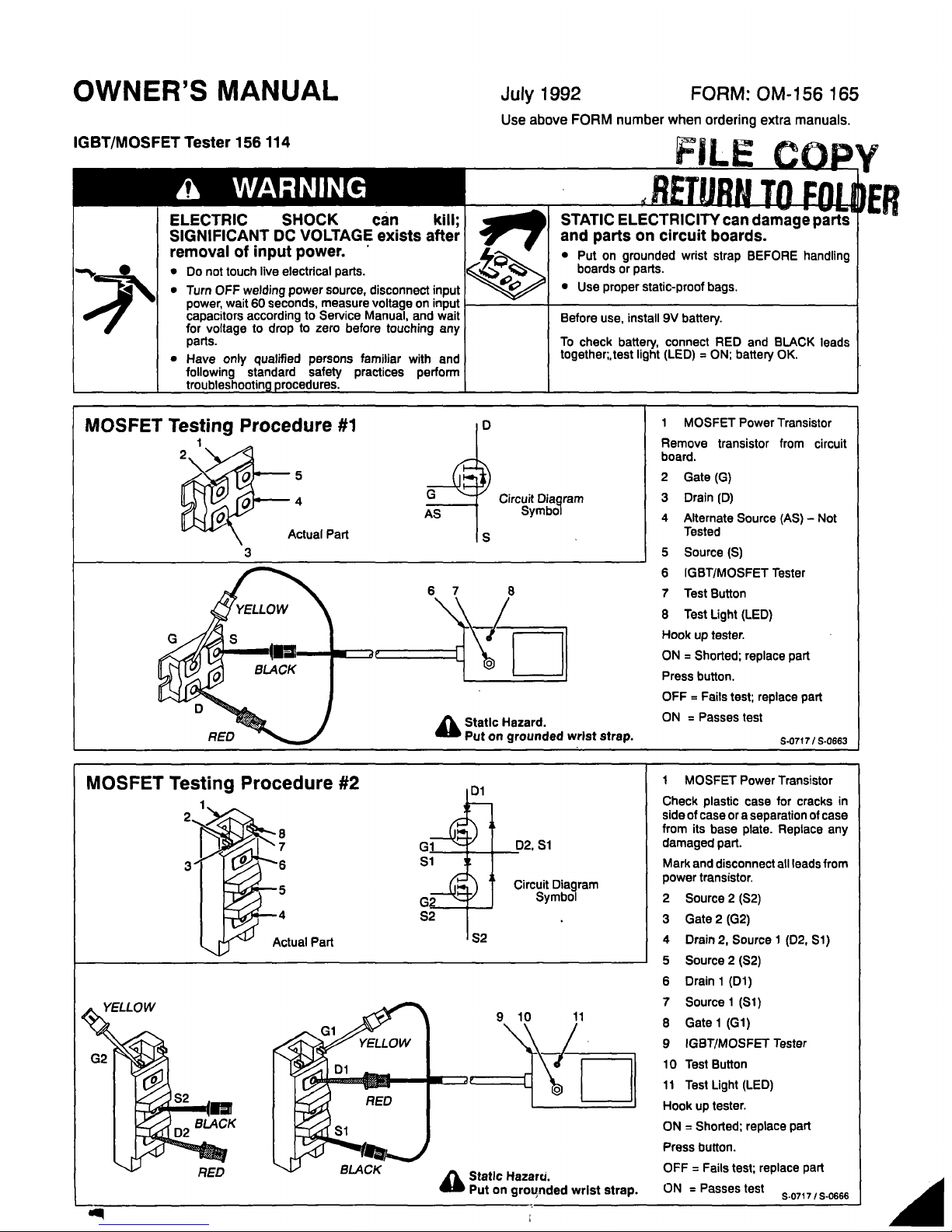
MOSFET
Testing
Procedure
#2
8
7
I
.5
Circuit
Diagram
Symbol
1
MOSFET
Power
Transistor
Check
plastic
case
for
cracks
in
side
of
caseora
separation
of
case
from
its
base
plate.
Replace
any
damaged
part.
Mark
and
disconnect
all
leads
from
power
transistor.
2
Source
2
(S2)
3
Gate
2
(G2)
4
Drain
2,
Source
1
(D2,
Si)
5
Source
2
(S2)
6
Drain
1
(Dl)
7
Source
1
(Si)
8
Gate
1
(Gi)
9
IGBT/MOSFET
Tester
10
Test
Button
11
Test
Light
(LED)
Hook
up
tester.
ON
=
Shorted:
replace
part
Press
button.
OFF=Fails
test;
replace
part
ON
=
Passes
test
S.o717/S~66
a
Static
Hazarci.
Put
on
grounded
wrist
Strap.
A
Dl
..
083850..
PB1
..
113333..
Ri
..
078431
R2
..
605916..
R3
.
605911
R4
..
092648..
iT
..
038785..
156119..
156120..
156170..
138044..
604825..
154095..
154096..
154097..
OM-156
165
Page
2
LIGHT,
md
red
lens
2V
LED
SWITCH,
PB
MC
NO
SPST
1A
115VAC
RESISTOR,
C
.25W
330
ohm
RESISTOR,
C
.25W
1K
ohm
RESISTOR,
C
.25W
10K
ohm
RESISTOR,
WW
fxd
zero
ohm
STRIP,
terminal
3P
solder
CASE
SECTION,
top/sides
CASE
SECTION,
bottom/ends
HOLDER,
battery
9V
BUSHING,
strain
relief
.120/.150
ID
x
.500mtg
hole
CABLE,
port
No.
18
3/c
(order
by
ft)
TEST
CLIP,
minigrabber
red
TEST
CLIP,
minigrabber
black
TEST
CLIP,
minigrabbe~
yellow
1
1
1
1
1
1
1
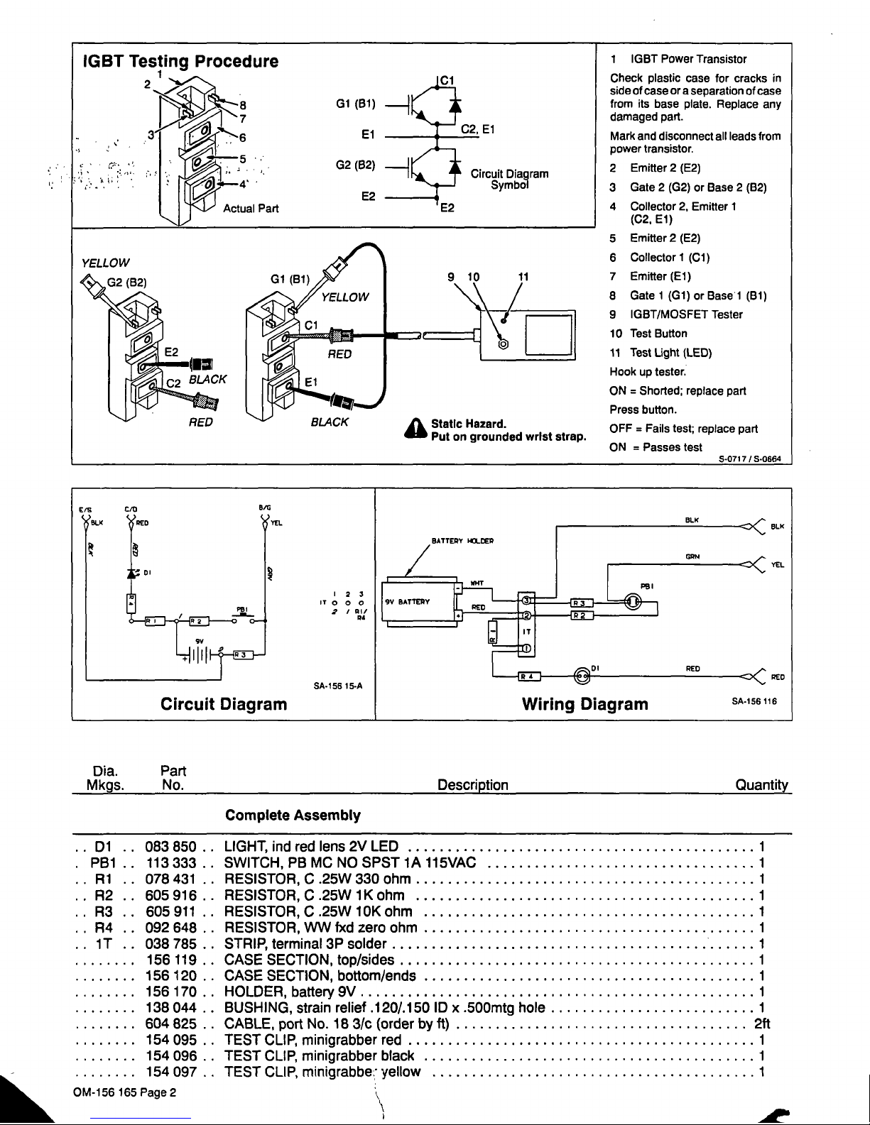
IGBTT
u
re
Actual
Part
Gi
(Bi)
~
El
El
G2
(B2)
H.~.....4
Circuit
Diagram
Symbol
E2
1
IGBT
Power
Transistor
Check
plastic
case
for
cracks
in
side
of
caseora
separation
of
case
from
its
base
plate.
Replace
any
damaged
part.
Mark
and
disconnect
all
leads
from
power
transistor.
2
Emitter
2
(E2)
3
Gate
2
(G2)
or
Base
2
(B2)
4
Collector
2,
Emitter
I
(C2.
El)
5
Emitter
2
(E2)
6
Collector
1
(Cl)
7
Emitter(El)
8
Gate
1
(G1)orBasel
(Bi)
9
IGBT/MOSFET
Tester
10
Test
Button
11
Test
Light
(LED)
Rook
up
tester.
ON
=
Shorted;
replace
part
Press
button.
OFF
=
Fails
test;
replace
part
ON
=
Passes
test
5~O717/S~O664
9 10
11
a
Static
Hazard.
Put
on
grounded
wrist
strap.
23
T
0 0 0
2
I
~II
p4
BLK
YEL
Circuit
Diagram
5A.156
15.A
Wiring
Diagram
RED
Dia.
Part
Mkgs.
No.
Description
Quantity
Complete
Assembly
SA-156
116
1
1
1
1
2ft
1
1
1
 Loading...