

Miller Edge RB-G-K10, RB-TX10 Installation Instructions Manual
INSTALLATION INSTRUCTIONS
Models: RB-G-K10, RB-TX10
IMPORTANT: THIS DEVICE MUST BE PROFESSIONALLY INSTALLED
READ AND UNDERSTAND ALL INSTRUCTIONS BEFORE BEGINNING INSTALLATION
The Miller Edge RBand Monitored Gate Edge Transmitter/Receiver system is intended to provide a wireless connection between a
monitored sensing edge and a motorized operator that controls the associated gate. The RBand Receiver is compatible with up to 3
RBand Transmitters on 2 channels; 6 total transmitters. RBand meets the 2016 UL 325 requirements for monitored devices and has
been certified as a UL 325 Recognized Component. It is designed for use with operators that comply with 2016 UL 325 using a Miller
Edge 10K Sensing Edge.
1. PARTS LIST
RB-G-K10 Contents:
• RBand Gate Edge Transmitter/Receiver System:
• RBand Edge Transmitter (RB-TX10)
• RBand Gate Edge Receiver (RB-G-RX10)
• Receiver antenna
• (2) 3.6V AA lithium batteries*
• (4) #6 pan head transmitter mounting screws
RB-TX10 Contents:
• RBand Gate Edge Transmitter (RB-TX10)
• (2) 3.6V AA lithium batteries*
• (4) #6 pan head transmitter mounting screws
Required:
• 1/8” flat blade screwdriver
• 1/4” flat blade screwdriver
• Miller Edge 10K (T2/blue band) Sensing Edge
• Coaxial cable for exterior mounted antenna
• Coaxial bulkhead adapter, female/female
Recommended:
• Multi-meter capable of reading 10KΩ
• Mounting screws as required for receiver
*Replacement 3.6V AA lithium batteries can be purchased
at your local electronics store or via Miller Edge.
2. RECEIVER: INSTALLATION
1. Remove the operator cover and turn off the power to the gate operator.
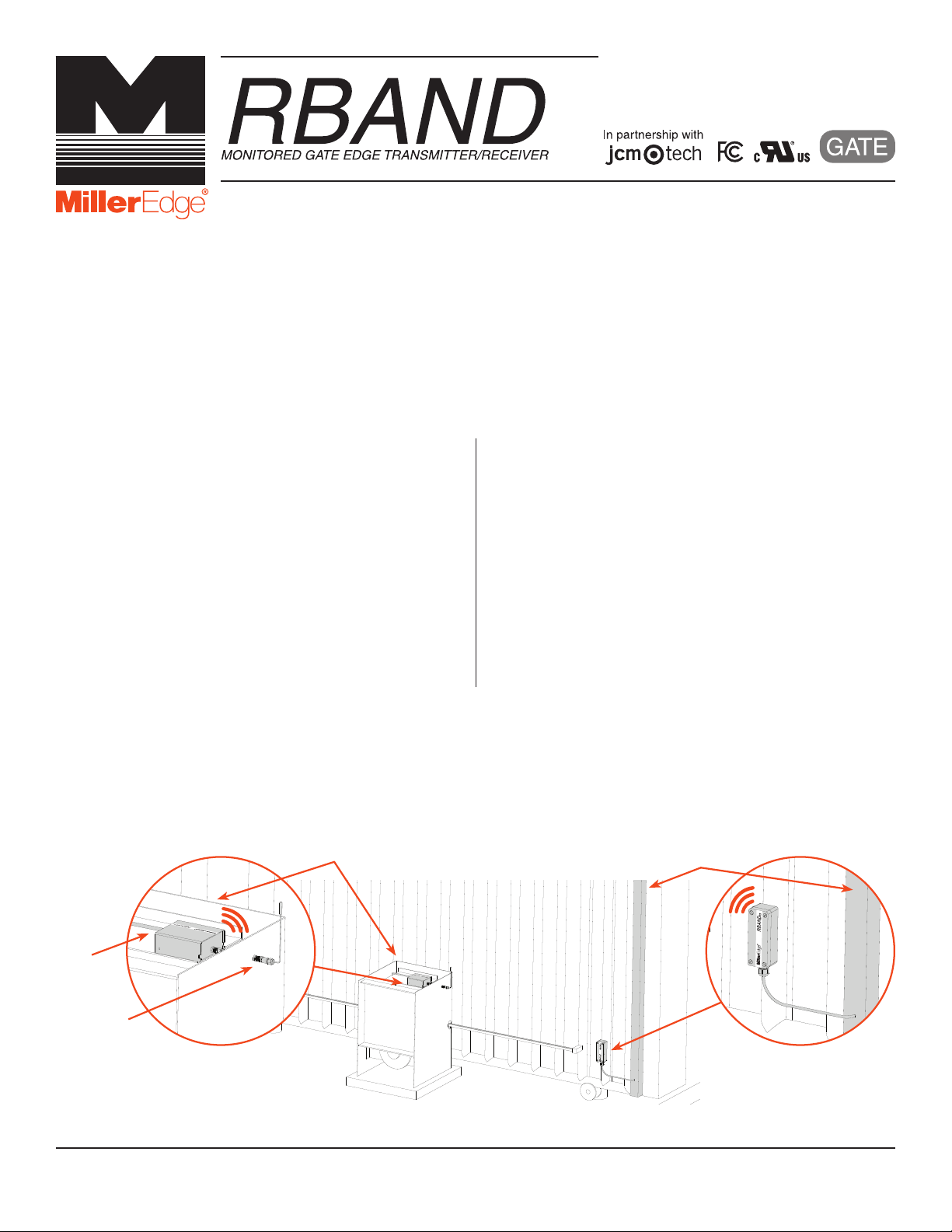
2. Determine where to place the external mounted antenna so it is in line of sight with the Transmitter(s) for the entire range of
travel [IMAGE 1]. Prepare the antenna coax as necessary.
3. Remove the Receiver cover and mount the base inside the operator, positioning it for optimum ease of wiring.
4. Connect power to the terminals marked 12/24 AC/DC (polarity sensitive) on the removable 8-pin connector [IMAGE 2].
OPERATOR
WIRING
ANTENNA
RBAND RECEIVER
MOUNTED INSIDE OPERATOR
WITH EXTERNAL ANTENNA
SENSING EDGE
RBAND TRANSMITTER
MOUNTED NEAR SENSING
EDGE
IMAGE 1. RBAND INSTALLATION WITH GATE EDGE
RB-G-K10_Install_20180712
www.milleredge.com info@milleredge.com 800-220-3343 1/5
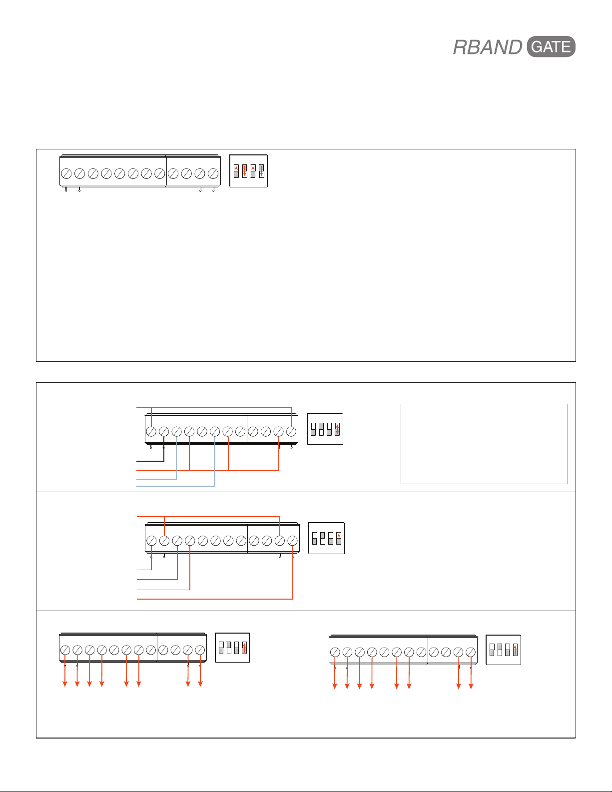
5. Determine which monitored interface your operator uses:
+12 or 24 VDC
GROUND
MON_CLOSE
COMMON
MON_OPEN
COMMON
COMMON
MON-12 VDC
12 or 24 VDC*
EDGE 1**
EDGE 2**
+12 VDC**
• 10K Operator [Table 1]: Connect the COM (C1/C2) and the correct output connections (BS1/BS2) to your operator. Set
DIP switch 4 to off.
• N.C. Operator [Table 2]: Connect the COM (C1/C2) and the correct output connections (CS1/CS2) to your operator. The
A Test terminals must be used for operators requiring N.C. inputs. Set DIP switch 4 to on.
6. Turn on power to the operator. Note: it takes ~5 seconds for the Receiver to initialize.
TABLE 1. REMOVABLE CONNECTORS
8-PIN CONNECTOR
Power
+12/24 AC/DC Constant power source
-12/24 AC/DC Constant power source (ground)
Relay Output 1
CS1 N.C. monitored input
C1 Monitored input Common
BS1 10K monitored input
Relay Output 2
CS2 N.C. monitored input
C2 Monitored input Common
BS2 10K monitored input
4-PIN CONNECTOR
Relay Output 3
NO3 Low battery alarm (optional)
C3 Low battery alarm (optional)
N.C. Power Cycling
COM COM: Switched power Common
A TEST +12/24VDC: Switched power source
CS1 C1 BS1 CS2C2BS2 NO3 C3
+ -
ON
1 2 3 4
TABLE 2. NORMALLY CLOSED OPERATORS: Removable Connector Assignments by Manufacturer
HySecurity
24 VDC
COMMON (not sensor common)
SENSOR COMMON
S1
S2
+ -
12/24 AC/DC
CS1 C1 BS1 CS2C2BS2 NO3 C3
COM. A TEST
ON
1 2 3 4
DIP Switch #4
• On to run
• Off to test
NOTE
For operator software at these versions
or higher, leave DIP switch 4 in the on
position:
• Smart Touch Controllers (STC): h4.56
• Smat DC Controllers (SDC): h5.57
• S.T.A.R.T.: v3.03
Ramset
VS (JP13, PIN 4)
24 VAC on terminal strip
NC (JP13, PIN 1)
COM (JP13, PIN 3)
VS (JP13, PIN 5)
All-O-Matic
CS1 C1 BS1 CS2C2BS2 NO3 C3
+ -
12/24 AC/DC
+ -
12/24 AC/DC
CS1 C1 BS1 CS2C2BS2 NO3 C3
ON
1 2 3 4
COM.A TEST
DIP Switch #4
• Turn to on
ON
1 2 3 4
COM.A TEST
DIP Switch #4
• Turn to on
Maximum Controls
CS1 C1 BS1 CS2C2BS2 NO3 C3
+ -
12/24 AC/DC
ON
1 2 3 4
COM.A TEST
DIP Switch #4
• Turn to on
GND*
GND**
GND**
GND**
www.milleredge.com info@milleredge.com 800-220-3343 2/5
 Loading...