

Miller Edge RBAND, RB-G-K10 Installation Instructions Manual
www.milleredge.com info@milleredge.com 800-220-3343
INSTALLATION INSTRUCTIONS
Model: RB-G-K10
IMPORTANT: THIS DEVICE MUST BE PROFESSIONALLY INSTALLED.
READ AND UNDERSTAND ALL INSTRUCTIONS BEFORE BEGINNING INSTALLATION.
The Miller Edge RBand Monitored Gate Edge Transmitter/Receiver system is intended to provide a wireless
connection between a monitored sensing edge and a motorized operator that controls the associated gate. RBand
meets the 2016 UL 325 requirements for monitored devices and has been certified as a UL 325 Recognized
Component. It is designed for use with operators that comply with 2016 UL 325 using a Miller Edge 10K Sensing
Edge.
1. PARTS LIST
Kit Contents:
1. RBand Edge Transmitter (RB-TX10)
2. RBand Gate Edge Receiver (RB-G-RX10)
3. Receiver antenna
4. (2) 3.6V AA lithium batteries*
5. (4) #6 pan head transmitter mounting screws
*Replacement 3.6V AA lithium batteries can be
purchased at your local electronics store or via
Miller Edge.
Required:
• 1/8” flat blade screwdriver
• 1/4” flat blade screwdriver
• Miller Edge 10K (T2/blue band) Sensing Edge
• Coaxial cable for exterior mounted antenna
• Coaxial bulkhead adapter, female/female
Recommended:
• Multi-meter capable of reading 10KΩ
• Mounting screws for the Receiver
2. RECEIVER: INSTALLATION
2-1. Remove operator cover and turn off the power to the gate operator.
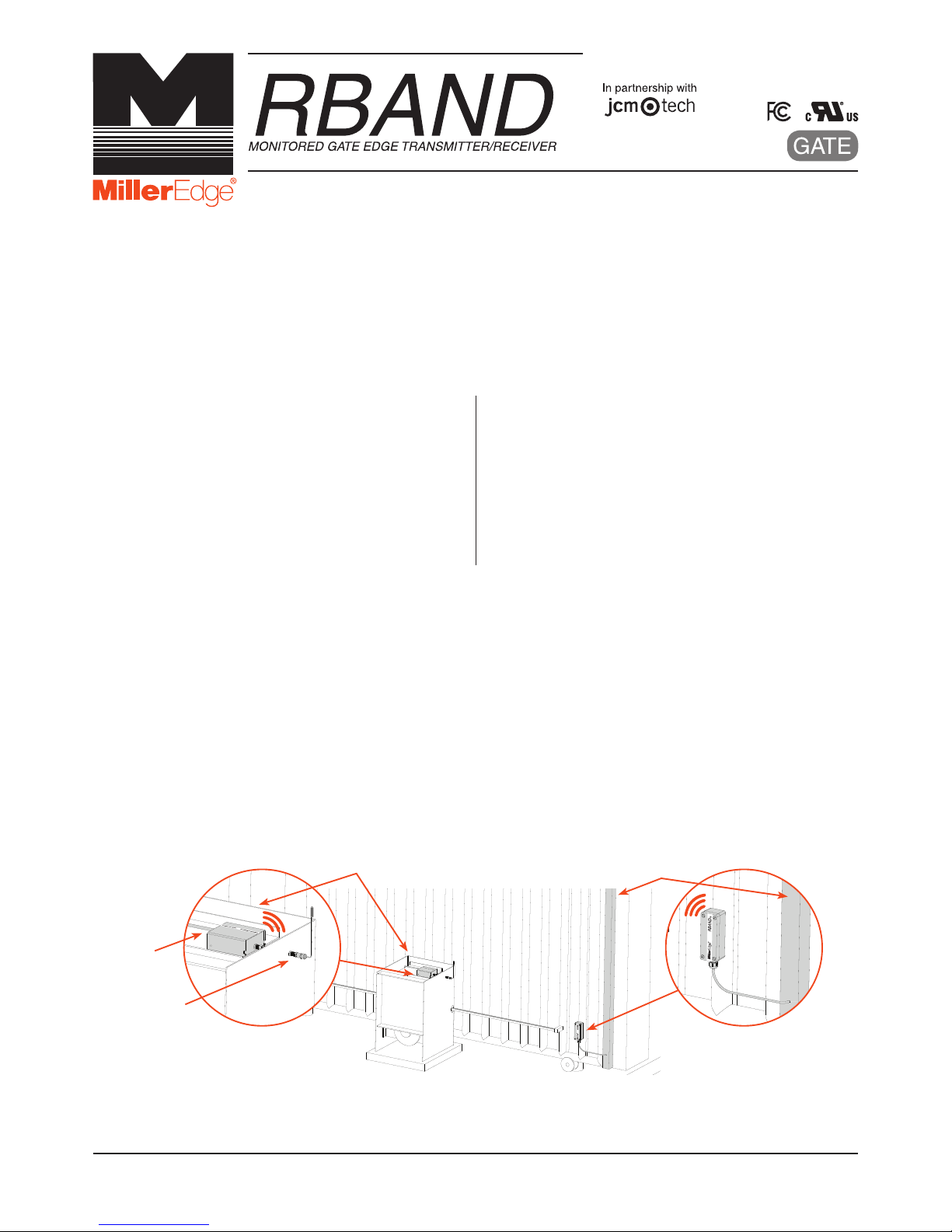
2-2. Determine where to place the external mounted antenna so it is in line of sight with the Transmitter for the
entire range of travel [IMAGE 1]. Prepare the antenna coax as necessary.
2-3. Remove Receiver cover and mount the base inside the operator, positioning it for optimum ease of wiring.
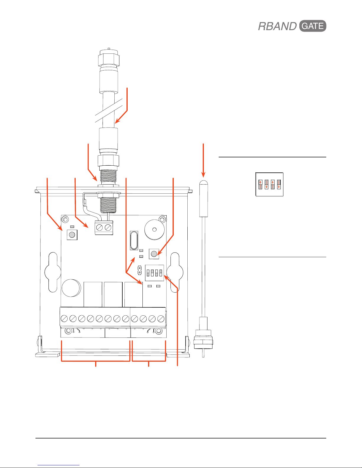
2-4. Connect power to the terminals marked 12/24 AC/DC (polarity sensitive) on the removable 8-pin
connector [IMAGE 2].
2-5. Determine which monitored interface your operator uses. Connect the COM (C1/C2) and the correct output
connections (N.C. = CS1/CS2 or 10K = BS1/BS2) to your operator. There are 2 separate relays (channels):
R1 and R2. The A Test terminals must be used for operators requiring N.C. inputs. Enable with DIP switch 4
[TABLE 1].
2-6. Replace the Receiver cover and turn on power to the operator. Note: it takes ~5 seconds for the Receiver to
initialize.
Note: RBand 10K Gate Edge Receiver is compatible with up to 3 RBand Transmitters on 2 channels (6 total).
RB-G-K10_Install_A4_20170706
IMAGE 1. RBand Transmitter Installation with Gate Edge
RBAND RECEIVER
MOUNTED INSIDE OPERATOR
WITH EXTERNAL ANTENNA
OPERATOR
ANTENNA
WIRING
RBAND TRANSMITTER
MOUNTED NEAR
SENSING EDGE
SENSING EDGE
www.milleredge.com info@milleredge.com 800-220-3343
IMAGE 2. RBAND GATE EDGE RECEIVER PCB & CONNECTIONS
LED INDICATORS
Initial Power
• No Transmitters Programmed:
R1 & R2 LEDs on
R1 or R2 LED
• Programmed: Off
• Fault Condition: On
R3 LED
• On when battery is low
A TEST LED
• On when in test mode
CHECK LED
(both channels programed)
• Programmed: Check LED flashes every
5 seconds
DIP SWITCH SETTINGS
ON
1 2 3 4
Switch 1-3: Leave switches in factory
default settings
Switch 4: Used to enable Normally Closed
cycle testing:
• N.C. Operator: Set to on and connect
the switched power to the A Test and
Common pins shown above
• 10K Operator: Set to off
TABLE 1.
REMOVABLE CONNECTORS
For Normally Closed gate operators,
please reference page 5.
8-PIN CONNECTOR
Power
+12/24 AC/DC Constant power source
-12/24 AC/DC Constant power source (ground)
Relay Output 1
CS1 N.C. monitored input
C1 Monitored input Common
BS1 10K monitored input
Relay Output 2
CS2 N.C. monitored input
C2 Monitored input Common
BS2 10K monitored input
4-PIN CONNECTOR
Relay Output 3
NO3 Low battery alarm (optional)
C3 Low battery alarm (optional)
N.C. Power Cycling
COM. COM: Switched power Common
A TEST +12/24VDC: Switched power
source
GND ANT
R2
R1
R3 A TEST
CHECK
PROG
ON
123
4
12/24 AC/DC
CS1 C1
+ -
BS1 CS2 C2 BS2 NO3 C3
COM.
A TEST
MR
PROGRAM
BUTTON
CHECK LED
& BUTTON
REMO
VABLE
8-PIN CONNECTOR
DIP SWITCHES
RELAY
LEDS
ANTENNA
TERMINAL
BLOCK
REMOVABLE
4-PIN CONNECTOR
COAXIAL CABLE
PROVIDED BY
INSTALLER
ANTENNA
F-CONNECTOR
COAX EXTENDER
 Loading...