

Miller Edge MGL-TX20, MGL-RX20, MGL-K20 Installation Instructions Manual
T
he
Monitor
s
afety
edge and a m
m
oni
tored dev
2016 U
L 325 us
READ AND UNDERSTAND ALL INSTRUCTIONS BEFORE BEGINNING INSTALLATION
ed
G
ate
Link
(
otor
i
z
i
c
es
and has
i
ng a
T2 ter
1-Parts List
PART NUMBER
Kit Contents:
1. MGL-TX20 Transmitter unit
2. MGL-RX20 Receiver unit
3. Receiver antenna
4. (2) AA lithium batteries
5. (4) #6 pan head transmitter mounting screws
MG
L)
tr
ans
ed operator
been c
er
m
i
nated edge s
ti
mitter
fi
ed as
t
hat
/r
a U
ens
ec
eiv
cont
r
L 325 rec
or
.
er
ols
s
y
t
s
tem
he
ogni
I
is
associat
z
S
IN
MPORTANT:
intended
ed c
ed
om
to
gat
ponent.
ION
T
C
U
R
T
S
IN
ION
T
A
L
L
TA
Model: MGL-K20
pr
o
v
ide
a
w
ir
eles
s
c
onnec
tion
betw
een
a
monitor
e
.
MGL
meet
s
t
he
2016
U
L
325
requi
rem
ents
It i
s
des
i
gned f
or us
e on oper
Required:
1. 1/8” flat blade screwdriver
2. 1/4” flat blade screwdriver
3. 10K (T2/blue band) terminated Sensing Edge
Recommended:
• VOM for test purposes
• Mounting screws as required for receiver
ators
that c
om
pl
y
w
S
ed
for
i
th
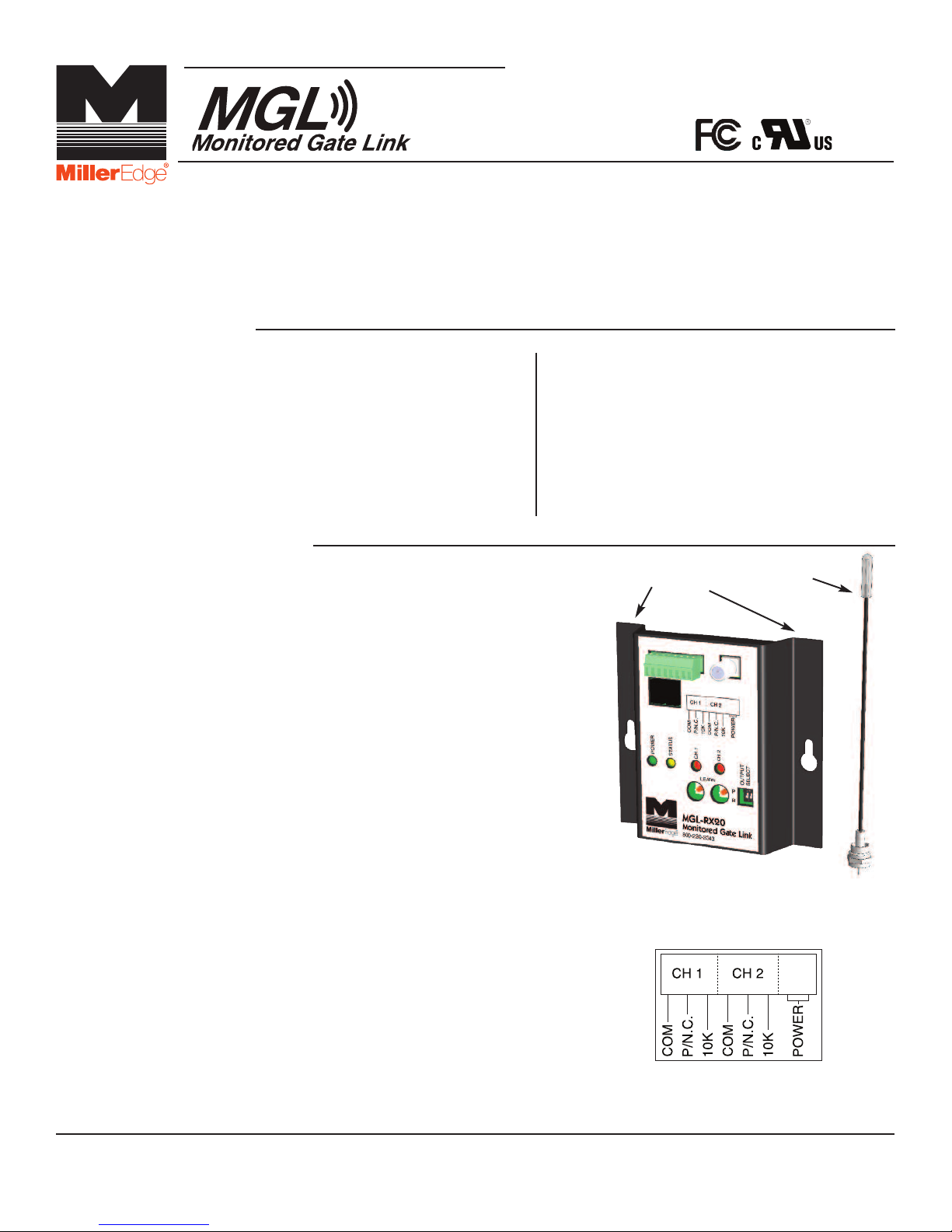
2-Install Receiver
2-1. Mount the Receiver inside the operator cover.
2-2. Attach the antenna to the Receiver. An extension
cable will be required if the operator cover is
metal. Ideally, antenna should be vertical and in
line-of-sight of the Transmitter(s).
2-3. Connect power (12-24 VAC/DC) to the terminals
marked POWER (not polarity sensitive).
Determine which monitored interface your
operator uses. Connect the COM and the
correct output connections (P/N.C., 10K) to your
operator. The Output Select dip switch 1 is
set to “R” for all operator’s requiring either a N.C.
or a 10K input, or set to “P” for operator’s that
require a pulsed input. Switch 2 has no function.
2-4. Apply power to the Receiver. Observe that the
green and yellow LEDs are on. The Channel 1
red LED will blink, and the Channel 2 LED will be
on solid. After 15 seconds, the Channel 2 LED will
go out, unless there is a Transmitter associated
with it. If the yellow LED is blinking randomly, at
least one Transmitter has been Learned and is
working.
TABS (2)
ANTENNAMOUNTING
RECEIVER
ENCLOSURE
P.O. Box 159 • West Grove, PA 19390 • 800-220-3343 • 610-869-4422 • Fax: 610-869-4423 • www.milleredge.com
6809 South Harl Avenue, Suite A • Tempe, AZ 85283 • 800-887-3343 • 480-755-3565 • Fax: 480-755-3558
TERMINAL
DIAGRAM
MGL-K20_Inst_20160815
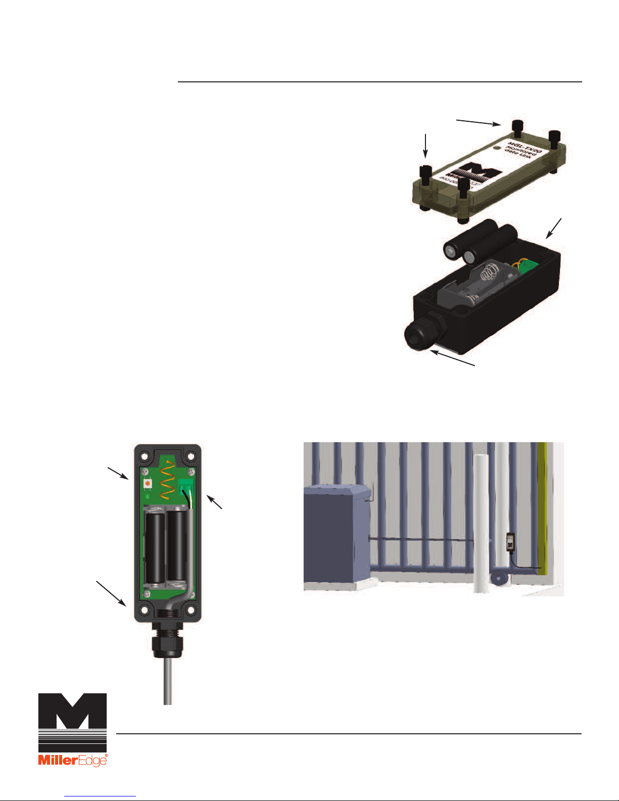
3-Learn Mode
3-1. Prior to mounting the Transmitter(s), remove the
cover(s) and insert the batteries, noting their polarity.
The green LED should blink once every second. Press
the Test button, next to the green LED, and note that
the green LED flashes rapidly 3 times.
3-2. To enter Learn mode for Channel 1, press and hold
the Learn button on the Receiver for ~2 seconds until
the yellow Status LED blinks rapidly and both Channel
1 and 2 red LEDs are on.
3-3. Press the Transmitter test button for ~2 seconds. Note
that the yellow Status LED and the red Channel 1
LED on the Receiver blink rapidly. Immediately release
the Transmitter Test button. Channel 1 is now
programmed. Channel 1 LED will be blinking rapidly
(indicating no Edge has been connected) until your 10K
Sensing Edge is connected to the Transmitter. Press
the Transmitter Test button again and note that the red
LED on the Receiver turns on solid.
3-4. If needed, perform same steps for Channel 2. Up to 2
different Transmitters may be programmed per channel.
3-5. To start over or erase programming, press and hold
both Learn buttons for ~3 seconds and release. Both
Channel 1 and 2 red LEDs will blink slowly. Restart the
Learn procedure.
OP LID
T
SCREWS
STRAIN RELIEF
FITTING
TRANSMITTER
CB
P
TEST BUTTON
(4) CORNER
MOUNTING HOLES
REMOVABLE
TERMINAL BLOCK
MGL INSTALLATION
WITH GATE EDGE & OPERATOR
P.O. Box 159 • West Grove, PA 19390 • 800-220-3343 • 610-869-4422 • Fax: 610-869-4423 • www.milleredge.com
6809 South Harl Ave., Suite A • Tempe, AZ 85283 • 800-887-3343 • 480-755-3565 • Fax: 480-755-3558
 Loading...