

Miller Edge MEL-K20, MEL-RX20, MEL-TX20 Installation Instructions Manual
2-
1.
Open
and
unpack
t
he
a
nt
en
na,
b
at
t
er
ies,
t
r
ansmit
t
er
an
d
r
ecei
ver
uni
t
s.
2-
2.
L
oosen
scr
e
ws
f
r
om
t
he
t
op
cover
and
r
e
move
t
he
lid.
2-
3
. Re
mo
v
e
th
e
Tr
a
n
s
mitte
r
PCB b
y
p
u
llin
g
u
p
wa
r
d
o
n
o
n
e
o
f th
e
s
ilic
o
n
e
c
a
p
s
.
2
-
4.
Rout
e
t
he
wi
r
es
f
r
om
t
he
mo
nit
o
r
ed
edge
t
hr
ou
gh
t
he
st
r
ai
n
r
e
li
ef
cabl
e
f
i
t
t
i
n
g
f
o
r
appr
oxi
mat
ely
f
our
inches.
St
r
ip
t
he
i
n
sulat
i
on
f
r
o
m
t
he
t
wo
wi
r
e
s
b
ack
¼”
a
nd
secur
e
t
h
e
wi
r
es
i
n
t
he
t
er
mi
nal
block
mar
ked
SE
1.
(Not polarized.)
A
Kno
cko
ut
(
K.
O.
)
swit
ch
may
be
wir
ed
t
o
t
he
Tx
t
e
r
min
al
st
r
ip
ma
r
ked
KO.
(
Either normally open or normally closed
switches may be used.
)
2-
5.
Pla
c
e
th
e
two
AA
L
ith
iu
m b
a
tte
r
ie
s
in
th
e
ir
h
o
ld
e
r
s
in
th
e
p
r
o
p
e
r
d
ir
e
c
tio
n
, p
a
y
in
g
a
tte
n
tio
n
to
th
e
(
+)
a
n
d
(
-
)
e
n
d
s
.
2
-
6
. Tu
c
k
th
e
wir
e
s
c
o
n
n
e
c
te
d
to
th
e
SE te
r
min
a
l b
lo
c
k
n
e
a
tly
b
e
twe
e
n
th
e
b
a
tte
r
ie
s
a
n
d
p
u
ll th
e
e
x
c
e
s
s
wir
e
b
a
c
k
th
r
o
u
g
h
th
e
s
tr
a
in
r
e
lie
f.
Re-seat
the
P
CB i
n
the case, and securely tighten the
cable
f
itti
ng.
2-7. S
et
the
Termi
nat
ion
Type switch to either 10K or DC.
(see A
ppendi
x) This selection must match the
Terminati
on Type in the S
afety Edge.
2-8. A
ddress Switches
S
et
the Group (red) and Address (blue) switches to the
desired position.
(Note the settings for reference when
setting up the Receiver.)
If
t
he Group
switch i
s set
to
0, the Address switch may be
set
t
o
any posi
ti
on bet
ween
0 and F.
If the Group switch is set to 1, the Address switch may be
set to any position between 0 and B.
(
The remaining positions, C, D, E, and F are reserved for
factory test.
)
P.O. Box 159 • West Grove, PA 19390 • 800-220-3343 • 610-869-4422 • Fax: 610-869-4423 • www.milleredge.com
6809 South Harl Ave., Suite A • Tempe, AZ 85283 • 800-887-3343 • 480-755-3565 • Fax: 480-755-3558
MEL-K20_Inst_20140708
Model # MEL-K20
I
N
ST
A
LLA
TI
O
N
I
N
STR
U
C
TI
O
N
S
IMPORTANT:
READ AND UNDERSTAND ALL INSTRUCTIONS BEFORE BEGINNING INSTALLATION.
Parts List
Kit Contents:
1. MEL-TX20 Transmitter Unit
2. MEL-RX20 Receiver Unit
3. Receiver Antenna
4. (2) AA Lithium Batteries
5. 3 ft. 20 AWG lead wire
6. (4) #6 Pan Head Transmitter Mounting Screws
1-
PART NUMBER
2- Install Transmitter and Test
T
h
e
M
o
n
i
t
o
r
e
d
E
d
g
e
L
i
n
k
(
M
EL)
t
r
a
n
s
m
i
t
t
e
r
/
r
e
c
e
i
v
e
r
s
y
s
t
e
m
i
s
i
n
t
e
n
d
e
d
t
o
p
r
o
v
i
d
e
a
w
i
r
e
l
e
s
s
c
o
n
n
e
c
t
i
o
n
b
e
t
w
e
e
n
a
m
o
n
i
t
o
r
e
d
s
a
f
e
t
y
e
d
g
e
a
n
d
a
m
o
t
o
r
i
z
e
d
o
p
e
r
a
t
o
r
th
a
t c
o
n
tro
ls
th
e
a
s
s
o
c
ia
te
d
d
o
o
r o
r g
a
te
. M
E
L
m
e
e
ts
th
e
U
L
-3
2
5
/2
0
1
0
r
e
q
u
i
r
e
m
e
n
t
s
f
o
r
m
o
n
i
t
o
r
e
d
d
e
v
i
c
e
s
a
n
d
h
a
s
b
e
e
n
c
e
r
t
i
f
i
e
d
a
s
a
U
L
3
2
5
r
e
c
o
g
n
i
z
e
d
c
o
m
p
o
n
e
n
t
.
I
t
i
s
d
e
s
i
g
n
e
d
f
o
r
u
s
e
o
n
o
p
e
r
a
t
o
r
s
t
h
a
t
c
o
m
p
l
y
w
i
t
h
U
L
3
2
5
-
2
0
1
0
u
s
i
n
g
a
T
2
o
r
T
3
t
e
r
m
i
n
a
t
e
d
e
d
g
e
s
e
n
s
o
r
.
Required:
1. 1/8” Flat blade screwdriver
2. 1/4” Flat blade screwdriver
3. T2 (10K/Blue Band) or T3 (DiodeCapacitor/Red Band)Terminated Sensing Edge
Recommended:
VOM for test purposes
Mounting screws as required for receiver
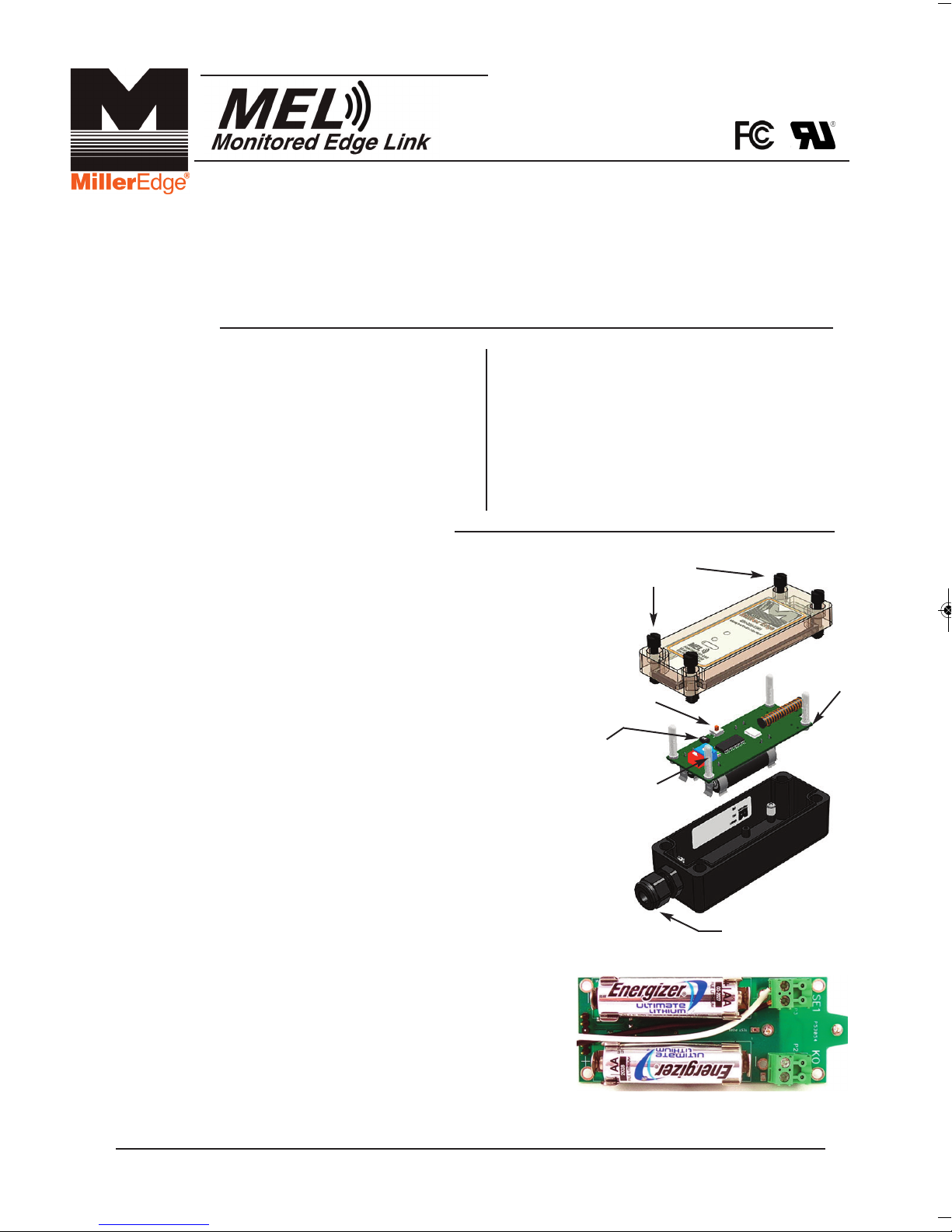
T
OP LID
SCREWS
TRANSMITTER
PCB
TEST BUTTON
TERMINATION
SELECTION
SILICONE
CAP (4)
STRAIN RELIEF
FITTING
(2-6) EDGE WIRING TO
TERMINAL BLOCK
P.O. Box 159 • West Grove, PA 19390 • 800-220-3343 • 610-869-4422 • Fax: 610-869-4423 • www.milleredge.com
6809 South Harl Ave., Suite A • Tempe, AZ 85283 • 800-887-3343 • 480-755-3565 • Fax: 480-755-3558
2-9. Momentarily press the TEST button. The Green Tx Data LED should flash.
(The Red Low Battery LED will only light when the batteries fall below 2.4v.)
2-10. Mount the Transmitter to the door or gate using #6 - 20 x 3/4” self-drilling screws.The mounting holes are
located under the Top Lid Screws. Mount the transmitter with the wire strain relief facing down or to the side.
2
-11. Replace the cover on the Transmitter and tighten the screws taking care to align the lid.
*Note the alignment pin located in the upper left corner.
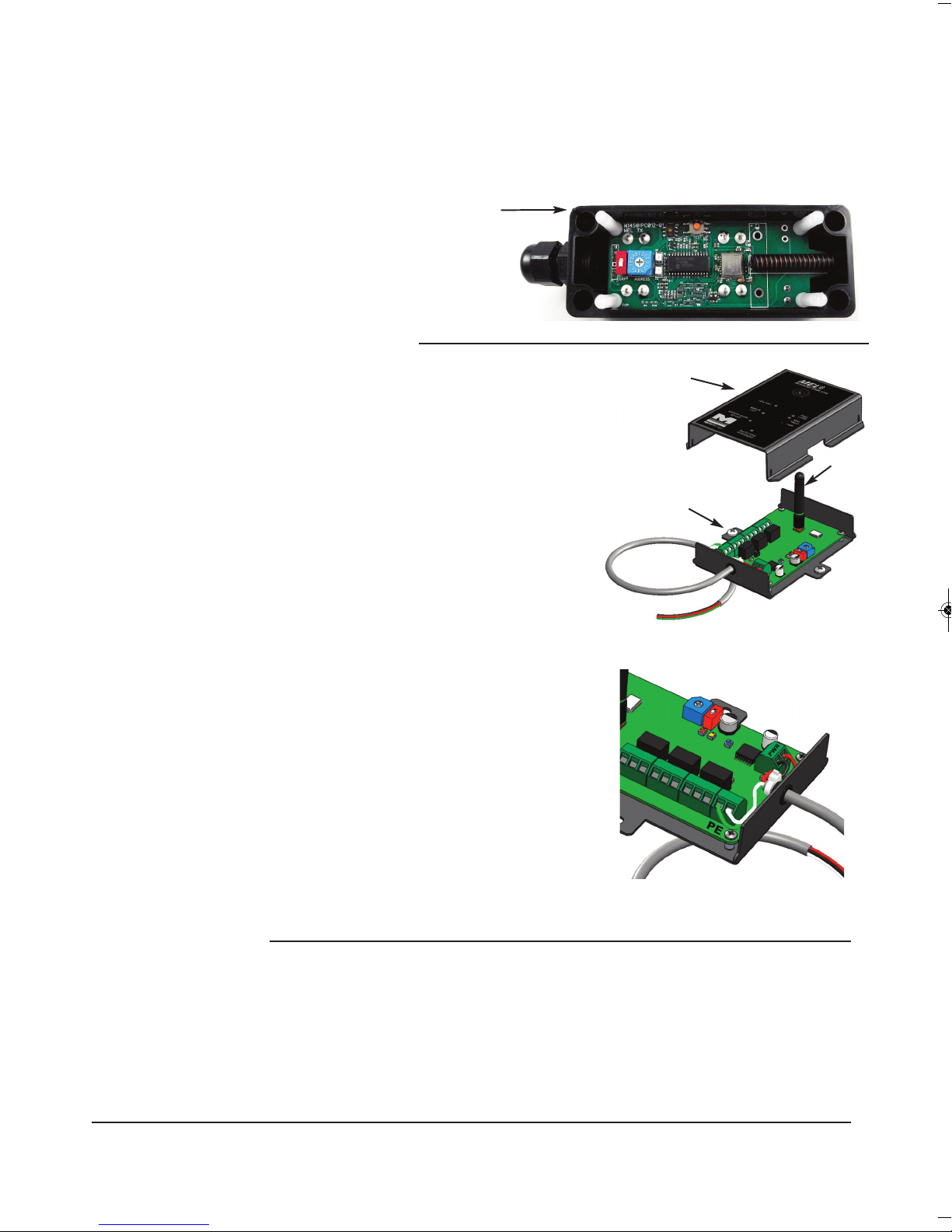
3- Install Receiver and Test
3-1. Remove lid of the Receiver Unit.
3-2. Set the Group (red) and Address (blue) switches to
match the transmitter settings.
3-3. Mount the receiver close to the operator and in-the-line-of-sight
of the transmitter using the mounting holes, as shown.
3-4. *Connect the receiver’s PE (Photo-Eye) output to the operator’s
PE input terminals using Green and White wires.
(Operator terminal label naming may differ. Contact factory for
support).
3-5. Connect the Black and Red wires to a 12 or 24V ac/dc source.
3-6. Attach the antenna to the receiver RF board.
3-7. Preliminary Test :
Confirm that the Transmitter and Receiver are powered ON.
Activate the Safety Edge (or monitored device).
The Address Valid Yellow LED on the Receiver should
flash momentarily.
If the Address Valid LED does not flash, check that the
Group and Address switches match the transmitter
settings. Confirm that the Photo-Eye and Safety Edge
LEDs are lit while the safety edge is held active.
Note that the Photo-Eye and Safety Edge LEDs
go OFF when the Edge is released.
3-8. Replace the Receiver Lid taking care to slip
the Antenna through the lids’ grommet.
*Certain installations may require an alternative wiring
scheme. Please consult factory for assistance.
4- Safety Test
4-1. While moving the door in the downward direction
or the gate in the desired direction, momentarily
activate the Safety Edge and confirm that the
door or gate stops and reverses direction.
(4) CORNER
MOUNTING HOLES
L
ID
ANTENNA
M
OUNTING
TABS (2)
RECEIVER
ENCLOSURE
FIGURE (3-4)
MEL-K20_Inst_20140708
 Loading...