

Miller Edge ME123 Installation Instructions Manual

INSTALLATION INSTRUCTIONS
1.5”H x 2”W
SENSING EDGE
ME123
IMPORTANT
Read and understand all instructions before beginning installation. All Miller Sensing Edges are inspected and tested before being
shipped to ensure against damage. If the shipping container appears to be damaged, please notify the carrier immediately.
The Miller Edge ME123 Style Sensing Edge is a UL Recognized Component that meets the UL 325 requirement. Compatible with most operator brands,
Sensing Edges are touch sensitive sensors designed to protect entrapment zones along the leading edge of automated doors or other motorized equipment.
Consult your manual for detailed instructions about connecting to the motor.
CONTENTS
• Miller Edge ME123 Sensing Edge
REQUIRED
• 18-22 gauge wire
• Miller Edge mounting channel
• Mounting channel mounting screws
OPTIONAL
• Connection methods:
Miller Edge wireless
edge transmitter/receiver
Coil cord
Retracting reel
Junction box(es)
• Signature Module (SM-101, SM-102)
SUGGESTED
• Operator installation manual
• Edge Tester (MET-101)
• Ohm meter (capable of measuring 10K)
1. INSTALLATION SETUP
1. All Miller Edge sensing edges are inspected and tested prior to shipment to ensure quality. Upon opening the shipping box, inspect your sensing
edge and wiring for shipping damage. If the shipping container appears to be damaged, please notify carrier immediately.
2. Un-box and lay the sensing edge out straight. This will allow the edge to relax and return to its original shape.
2A. MOUNTING CHANNEL INSTALLATION (DOORS)
ME123-C2175
PVC
1.5”H x 2”W
ME123-C3
PVC
1. Slide the edge into the mounting channel.
2. Align the edge and mounting channel to the leading edge of the door.
3. Adjust the close limits on the motor for a maximum compression of
.25” (6 mm).
4. Attach the channel to the by drilling self-tapping screws into the
mounting channel, starting 3” (7 cm) from the ends and spaced
approximately every 24”.
ME123-C
PVC
ME123-CA3
Aluminum
TECH TIP
To compensate for floor irregularities, gently curve the mounting channel
up or down to close any gaps between the edge and the floor, wall, or
other permanent fixture.
2B. MOUNTING CHANNEL INSTALLATION (OTHER)
1. Attach the channel to the by drilling self-tapping screws into the
mounting channel, starting 3” (7 cm) from the ends and spaced
approximately every 24”.
2. Slide the edge into the mounting channel.
3. Adjust the close limits on the motor for a maximum compression
of .25” (6 mm).
ME123-C7
PVC
MOUNTING CHANNEL STYLES &
POSSIBLE HARDWARE PLACEMENT
ME123-C1
PVC
ME123_Inst_20180926
www.milleredge.com info@milleredge.com 800-220-3343 1/4
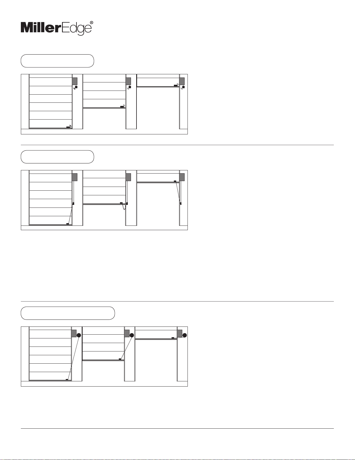
3. SENSING EDGE INSTALLATION
ME123 SENSING EDGE
WIRELESS METHOD
COIL CORD METHOD
Note: For specific operator input connection diagrams
and instructions, please consult your operator manual.
REQUIRED
Miller Edge wireless edge transmitter/receiver system
INSTALLATION
1. Consult the Miller Edge transmitter/receiver installation
instructions for wiring of the sensing edge.
2. For proper connection to operator inputs, please consult
the operator manual.
REQUIRED
Junction boxes (2) Mounting screws
Wire end caps 18-22 gauge wire
INSTALLATION
1. Mount the first junction box on the end stile or bottom bar
of the door.
2. Run the sensing edge lead wire into the junction box.
3. Mount the second junction box on an adjoining wall,
midway between the floor and the operator.
4. With the door in the closed position, secure the coil cord
to the first junction box.
5. Then run it, fully stretched, to the second wall mounted
junction box so the stretched length is equal to one-half of
the door opening.
6. Secure the coil cord into the wall junction box and trim the
coil cord. This assures the excess coil cord will not get
caught or hang in the opening of the door.
7. Secure 18-22 gauge wire into the second wall-mounted
junction box and hard wire to the operator sensing edge
terminals.
RETRACTING REEL METHOD
REQUIRED
Junction box (1) Mounting screws
Wire end caps 18-22 gauge wire
INSTALLATION
NOT SUITABLE FOR MONITORED SENSING EDGES
1. Mount the junction box on the end stile or bottom bar of
the door.
2. Run the sensing edge lead wire into the junction box.
3. Mount the retracting reel on an adjoining wall, near the
operator.
4. With the door in the closed position, secure the retracting
reel cable to the junction box. The cable should freely
Note: For specific operator input connection diagrams
and instructions, please consult your operator manual.
extend, without rubbing, in and out of the retracting reel for
the duration of the open/close cycle.
5. Using the 18-22 gauge wire, hardwire the retracting reel to
the sensing edge terminals of the operator.
www.milleredge.com info@milleredge.com 800-220-3343 2/4
 Loading...