

Page 1

OM-1500-17 218 022E
September 2005
Processes
MIG (GMAW) Welding
Description
Semi-Automatic, Air-Cooled,
MIG (GMAW) Welding Gun
™
®
XR -A Python 25 Ft.
Visit our website at
www.MillerWelds.com
200 Ampere Push-Pull Welding Gun
File: MIG (GMAW)
Page 2
From Miller to You
Thank you and congratulations on choosing Miller. Now you can get
the job done and get it done right. We know you don’t have time to do
it any other way.
That’s why when Niels Miller first started building arc welders in 1929,
he made sure his products offered long-lasting value and superior
quality. Like you, his customers couldn’t afford anything less. Miller
products had to be more than the best they could be. They had to be the
best you could buy.
Today, the people that build and sell Miller products continue the
tradition. They’re just as committed to providing equipment and service
that meets the high standards of quality and value established in 1929.
This Owner’s Manual is designed to help you get the most out of your
Miller products. Please take time to read the Safety precautions. They
will help you protect yourself against potential hazards on the worksite.
We’ve made installation and operation quick
and easy. With Miller you can count on years
of reliable service with proper maintenance.
And if for some reason the unit needs repair,
there’s a Troubleshooting section that will
help you figure out what the problem is. The
Miller is the first welding
equipment manufacturer in
the U.S.A. to be registered to
the ISO 9001:2000 Quality
System Standard.
parts list will then help you to decide the
exact part you may need to fix the problem.
Warranty and service information for your
particular model are also provided.
Working as hard as you do
− every power source from
Miller is backed by the most
hassle-free warranty in the
business.
Miller Electric manufactures a full line
of welders and welding related equipment.
For information on other quality Miller
products, contact your local Miller distributor to receive the latest full
line catalog or individual specification sheets. To locate your nearest
distributor or service agency call 1-800-4-A-Miller, or visit us at
www.MillerWelds.com on the web.
Mil_Thank 4/05
Page 3

TABLE OF CONTENTS
SECTION 1 −SAFETY PRECAUTIONS FOR GMAW WELDING GUNS − READ BEFORE USING 1 . . . . . . . .
1-1. Symbol Usage 1 . . . . . . . . . . . . . . . . . . . . . . . . . . . . . . . . . . . . . . . . . . . . . . . . . . . . . . . . . . . . . . . . . . . . . . . .
1-2. GMAW Gun Hazards 1 . . . . . . . . . . . . . . . . . . . . . . . . . . . . . . . . . . . . . . . . . . . . . . . . . . . . . . . . . . . . . . . . . .
EMF INFORMATION 2 . . . . . . . . . . . . . . . . . . . . . . . . . . . . . . . . . . . . . . . . . . . . . . . . . . . . . . . . . . . . . . . . . . . . . . . . . .
SECTION 2 − DEFINITIONS 3 . . . . . . . . . . . . . . . . . . . . . . . . . . . . . . . . . . . . . . . . . . . . . . . . . . . . . . . . . . . . . . . . . . .
2-1. Warning Label Definitions 3 . . . . . . . . . . . . . . . . . . . . . . . . . . . . . . . . . . . . . . . . . . . . . . . . . . . . . . . . . . . . . .
2-2. Symbols And Definitions 4 . . . . . . . . . . . . . . . . . . . . . . . . . . . . . . . . . . . . . . . . . . . . . . . . . . . . . . . . . . . . . . .
SECTION 3 − INSTALLATION 5 . . . . . . . . . . . . . . . . . . . . . . . . . . . . . . . . . . . . . . . . . . . . . . . . . . . . . . . . . . . . . . . . . .
3-1. Specifications 5 . . . . . . . . . . . . . . . . . . . . . . . . . . . . . . . . . . . . . . . . . . . . . . . . . . . . . . . . . . . . . . . . . . . . . . . .
3-2. Gun Lead Connections 5 . . . . . . . . . . . . . . . . . . . . . . . . . . . . . . . . . . . . . . . . . . . . . . . . . . . . . . . . . . . . . . . .
SECTION 4 − OPERATION 6 . . . . . . . . . . . . . . . . . . . . . . . . . . . . . . . . . . . . . . . . . . . . . . . . . . . . . . . . . . . . . . . . . . . .
4-1. Controls and Settings 6 . . . . . . . . . . . . . . . . . . . . . . . . . . . . . . . . . . . . . . . . . . . . . . . . . . . . . . . . . . . . . . . . . .
4-2. Drive Roll Removal/Installation 7 . . . . . . . . . . . . . . . . . . . . . . . . . . . . . . . . . . . . . . . . . . . . . . . . . . . . . . . . . .
4-3. Idler Roll Removal/Installation 8 . . . . . . . . . . . . . . . . . . . . . . . . . . . . . . . . . . . . . . . . . . . . . . . . . . . . . . . . . . .
SECTION 5 − MAINTENANCE & TROUBLESHOOTING 9 . . . . . . . . . . . . . . . . . . . . . . . . . . . . . . . . . . . . . . . . . . .
5-1. Routine Maintenance 9 . . . . . . . . . . . . . . . . . . . . . . . . . . . . . . . . . . . . . . . . . . . . . . . . . . . . . . . . . . . . . . . . . .
5-2. Troubleshooting Guide 9 . . . . . . . . . . . . . . . . . . . . . . . . . . . . . . . . . . . . . . . . . . . . . . . . . . . . . . . . . . . . . . . . .
5-3. Troubleshooting Table 10 . . . . . . . . . . . . . . . . . . . . . . . . . . . . . . . . . . . . . . . . . . . . . . . . . . . . . . . . . . . . . . . . .
SECTION 6 − ELECTRICAL DIAGRAMS 11 . . . . . . . . . . . . . . . . . . . . . . . . . . . . . . . . . . . . . . . . . . . . . . . . . . . . . . . .
SECTION 7 − PARTS LIST 12 . . . . . . . . . . . . . . . . . . . . . . . . . . . . . . . . . . . . . . . . . . . . . . . . . . . . . . . . . . . . . . . . . . . . .
SECTION 8 − OPTIONS AND ACCESSORIES 18 . . . . . . . . . . . . . . . . . . . . . . . . . . . . . . . . . . . . . . . . . . . . . . . . . . .
WARRANTY
Page 4

Declaration of Conformity for
European Community (CE) Products
NOTE
Manufacturer: European Contact:
Miller Electric Mg. Co. Mr. Danilo Fedolfi,
1635 W. Spencer St. Managing Director
Appleton, WI 54914 USA ITW Welding Products Italy S.r.l.
Phone: (920) 734-9821 Via Privata Iseo 6/E
European Contact Signature:
Declares that the product: Python
This information is provided for units with CE certification (see rating label on unit).
20098 San Giuliano
Milanese, Italy
Phone: 39(02)98290-1
Fax: 39(02)98290203
®
conforms to the following Directives and Standards:
Directives
Low Voltage Directive: 73/23/EEC
Electromagnetic Compatibility (EMC) Directive: 89/336/EEC
Standards
Arc Welding Equipment − Part 5: Wire Feeders. IEC 60974-5 Ed. 1
Arc Welding Equipment − Part 10: Electromagnetic Compatibility (EMC) Requirements. IEC 60974-10 August 2002
Arc Welding Equipment − Part 1: Welding Power Sources. IEC 60974-1 Ed. 2.1
Degrees Of Protection Provided By Enclosure (IP Code) IEC 60529 Ed. 2.1
Insulation Coordination For Equipment Within Low-Voltage Systems −
Part 1: Principles, Requirements and Tests: IEC 60664-1 Ed. 1.1
Arc Welding Equipment − Part 7: Torches. IC 60974-7 Ed.1
The product technical file is maintained by the responsible Business Unit(s) located at the manufacturing facility.
dec_wire_6/05
Page 5
SECTION 1 −SAFETY PRECAUTIONS FOR GMAW
WELDING GUNS − READ BEFORE USING
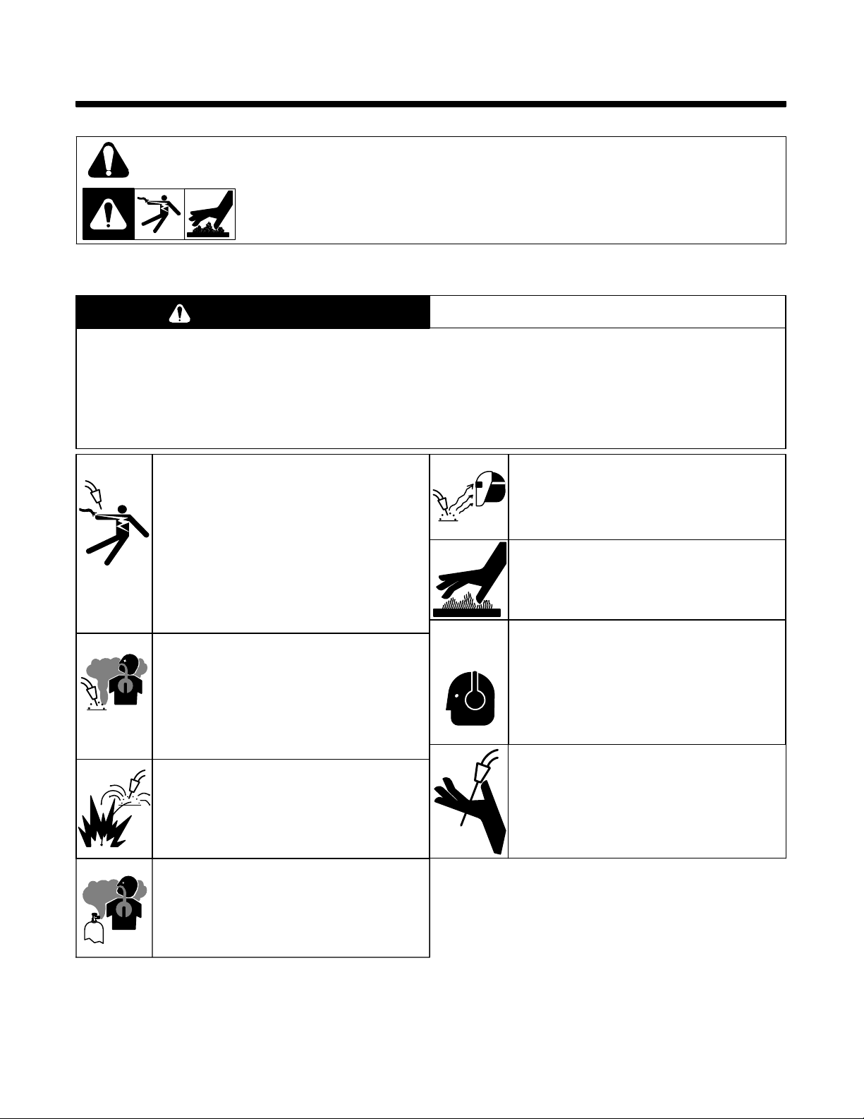
1-1. Symbol Usage
SR7_8/03
Means Warning! Watch Out! There are possible hazards with this
procedure! The possible hazards are shown in the adjoining symbols.
This group of symbols means Warning! Watch Out! Possible ELECTRIC SHOCK and HOT PARTS hazards.
Consult symbols and related instructions below for necessary actions to avoid the hazards.
Y Marks a special safety message.
. Means NOTE; not safety related.
1-2. GMAW Gun Hazards
WARNING
PROTECT YOURSELF AND OTHERS FROM POSSIBLE SERIOUS INJURY OR DEATH. KEEP CHILDREN
AWAY. PACEMAKER WEARERS KEEP AWAY UNTIL CONSULTING YOUR DOCTOR.
In welding, as in most jobs, exposure to certain hazards occurs. Welding is safe when precautions are taken. The
safety information given below is only a summary of the more complete safety information found in the wire feeder
and welding power source Owner’s Manuals. Read and follow all safety precautions.
HAVE ALL INSTALLATION, OPERATION, MAINTENANCE, AND REPAIR WORK PERFORMED ONLY BY
QUALIFIED PEOPLE.
ELECTRIC SHOCK can kill.
1. Always wear dry insulating gloves.
2. Insulate yourself from work and ground.
3. Do not touch live electrode or electrical parts.
4. Repair or replace worn, damaged, or cracked
gun or cable insulation.
5. Turn off welding power source before changing
contact tip or gun parts.
6. Keep all covers and handle securely in place.
GMAW WELDING can be hazardous.
ARC RAYS can burn eyes and skin.
1. Wear welding helmet with correct shade of filter.
2. Wear correct eye and body protection.
3. Cover exposed skin with spatter-resistant
clothing.
HOT SURFACES can burn skin.
1. Allow gun to cool before touching.
2. Do not touch hot metal.
3. Protect hot metal from contact by others.
FUMES AND GASES can be hazardous
to your health.
1. Keep your head out of the fumes.
2. Ventilate area, or use breathing device.
3. Read Material Safety Data Sheets (MSDSs) and
manufacturer’s instructions for material used.
WELDING can cause fire or explosion.
1. Do not weld near flammable material.
2. Do not weld on closed containers.
3. Watch for fire; keep extinguisher nearby.
BUILD UP OF GAS can injure or
kill
1. Shut off shielding gas supply when not in
use.
2. Always ventilate confined spaces or use
approved air-supplied respirator.
NOISE can damage hearing; SOME
APPLICATIONS, SUCH AS PULSING,
are noisy.
1. Check for noise level limits exceeding those
specified by OSHA.
2. Use approved ear plugs or ear muffs if noise level
is high.
3. Warn others nearby about noise hazard.
WELDING WIRE can cause puncture
wounds.
1. Keep hands and body away from gun tip when
trigger is pressed.
OM-1500-17 Page 1
Page 6

EMF INFORMATION
NOTE
The following is a quotation from the General Conclusions Section of
the U.S. Congress, Office of Technology Assessment, Biological
Effects of Power Frequency Electric & Magnetic Fields −
Background Paper, OTA-BP-E-53 (Washington, DC: U.S.
Government Printing Office, May 1989): “. . . there is now a very large
volume of scientific findings based on experiments at the cellular
level and from studies with animals and people which clearly
establish that low frequency magnetic fields can interact with, and
produce changes in, biological systems. While most of this work is
of very high quality, the results are complex. Current scientific
understanding does not yet allow us to interpret the evidence in a
single coherent framework. Even more frustrating, it does not yet
allow us to draw definite conclusions about questions of possible risk
or to offer clear science-based advice on strategies to minimize or
avoid potential risks.”
Considerations About Welding And The Effects Of Low Frequency Electric And
Magnetic Fields
To reduce magnetic fields in the workplace, use the following
procedures:
1. Keep cables close together by twisting or taping them.
2. Arrange cables to one side and away from the operator.
3. Do not coil or drape cables around the body.
4. Keep welding power source and cables as far away as practical.
5. Connect work clamp to workpiece as close to the weld as
possible.
About Pacemakers:
The above procedures are among those also normally
recommended for pacemaker wearers. Consult your doctor for
complete information.
mod10.1 4/93
OM-1500-17 Page 2
Page 7
SECTION 2 − DEFINITIONS
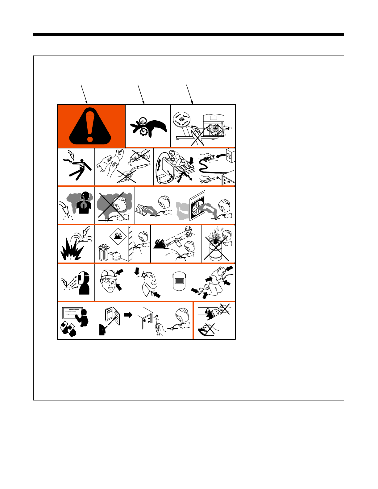
2-1. Warning Label Definitions
ABC
1 1.1 1.2 1.3
2
3 3.1 3.2 3.3
4 4.1
2.1
2.2
+
56
+
+
2.3
+
S-178 936
A. Warning! Watch Out! There
are possible hazards as
shown by the symbols.
B. Drive rolls can injure fingers.
C. Welding wire and drive parts
are at welding voltage during
operation − keep hands and
metal objects clear.
1 Electric shock can kill.
1.1 Wear dry insulating gloves.
Do not touch electrode with
bare hand. Do not wear wet or
damaged gloves.
1.2 Protect yourself from electric
shock by insulating yourself
from work and ground.
1.3 Disconnect input plug or
power before working on
machine.
2 Breathing welding fumes can
be hazardous to your health.
2.1 Keep your head out of the
fumes.
2.2 Use forced ventilation or local
exhaust to remove the fumes.
2.3 Use ventilating fan to remove
fumes.
3 Welding sparks can cause
explosion or fire.
3.1 Keep flammables away from
welding. Don’t weld near
flammables.
3.2 Welding sparks can cause
fires. Have a fire extinguisher
nearby and have a watch
person ready to use it.
3.3 Do not weld on drums or any
closed containers.
4 Arc rays can burn eyes and
injure skin.
4.1 Wear hat and safety glasses.
Use ear protection and button
shirt collar. Use welding
helmet with correct shade of
filter. Wear complete body
protection.
5 Become trained and read the
instructions before working on
the machine or welding.
6 Do not remove or paint over
(cover) the label.
OM-1500-17 Page 3
Page 8
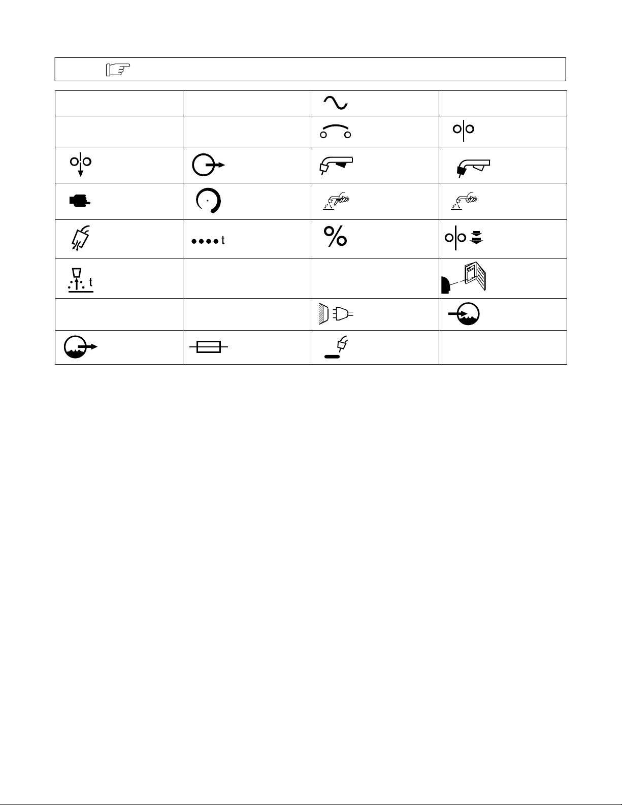
2-2. Symbols And Definitions
IP
Note
A
I
1
Some symbols are found only on CE products.
Amperes
Degree Of
Protection
Jog Output Trigger Gun
Press To Set Increase Trigger Hold On Trigger Hold Off
Purge Spot Weld Time Percent Run-In
Burnback Time
Primary Current
Water (Coolant)
Output
V
Hz
U
1
I
2
Volts Alternating Current
Hertz Circuit Breaker Wire Feed
Primary Voltage
Rated Current Line Connection
Fuse
U
2
Load Voltage Read Instructions
Continuous
Spot Welding
X
Water (Coolant) In-
Duty Cycle
put
OM-1500-17 Page 4
Page 9
SECTION 3 − INSTALLATION
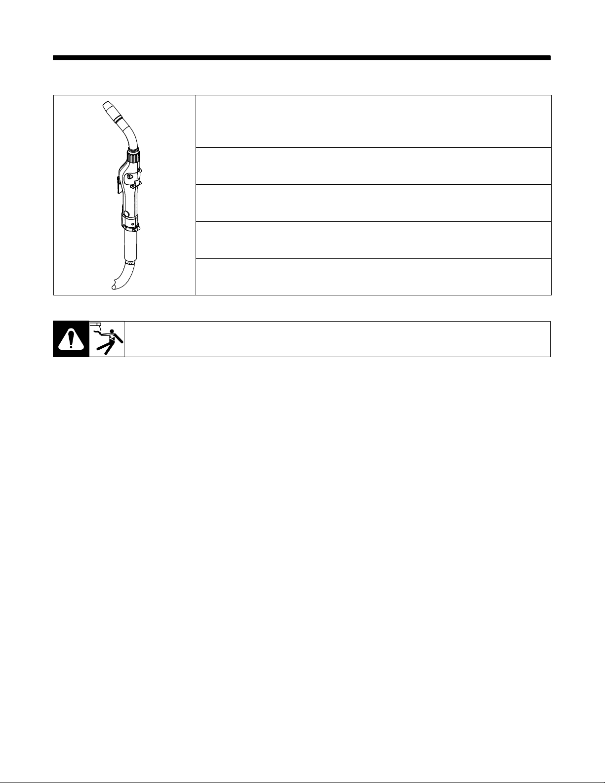
3-1. Specifications
Wire Capacity
Aluminum and Cored wire - .030 in - 1/16 in (0.8 mm - 1.6 mm)
Solid and Hard wire - .030 in - .045 in (0.6 mm - 1.2 mm)
Wire Speed
At rated feeder input voltage - 70-875 Ipm (22.2 mpm)
Duty Cycle - 100% (200 Amps peak)
All ratings are based from using Argon gas
Gun Weight
Less leads − 2.5 lbs (1.13 kg)
Shipping Weight
Approximately 19.29 lbs (8.29 kg)
Ref. 803 870-A
3-2. Gun Lead Connections
Power Cable - A #2 AWG power cable is used. The gun end of the cable has a fitting crimped to the copper cable
strands. This fitting is then threaded into the gun body. The cabinet end of the power cable is incorporated into the
Power Pin connector.
Conduit - Poly-lined conduit, for feeding aluminum wire. The longer fitting with a shallow groove is used on the gun
end. A set screw located on top of the gun handle secures the conduit in place. The cabinet end of the conduit is incorporated into the Power Pin connector.
Gas Hose - The gas hose is pushed over a barbed fitting on the gun body and secured with a plastic tie wrap. The
cabinet end of the gas hose is incorporated into the Power Pin connector.
Electric Cable - A multi-conductor control cable is used. The gun end of the cable is secured with a cable clamp and
the wires are connected to the potentiometer, the micro switch, the motor and the gun body mechanically. The cabinet
end of the control cable uses a 10-Pin, Amphenol connector.
OM-1500-17 Page 5
Page 10
SECTION 4 − OPERATION
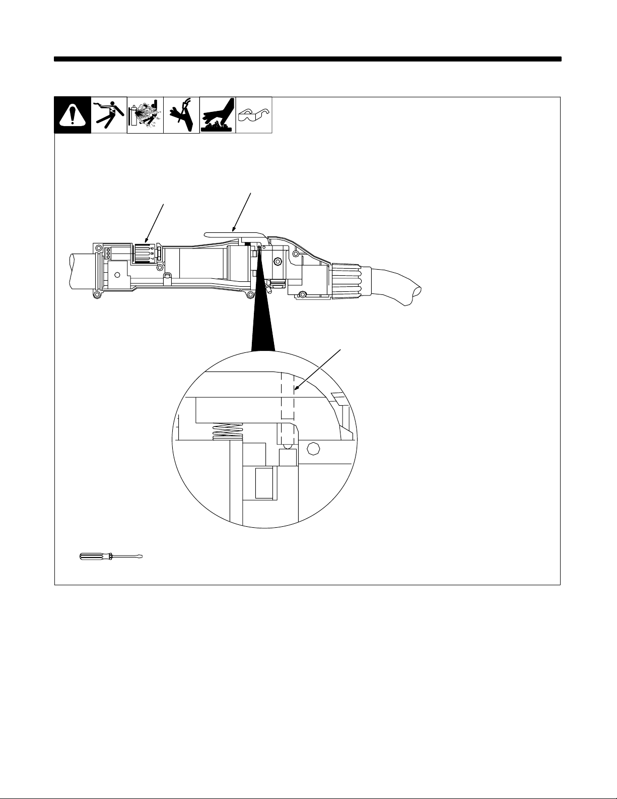
4-1. Controls and Settings
1
1 Potentiometer
The potentiometer is located in the
lower end of the handle, providing
up to 875 ipm (22.2 mpm) with 3 3/4
turns.
2 Trigger
3 Trigger Sensitivity
2
3
Adjustment Screw
The amount of trigger level travel
can be shortened for quicker response action.
A more sensitive trigger lever is
produced by reducing the gap between the trigger lever and the micro switch lever. Turning the trigger sensitivity adjustment screw
clockwise closes the gap between
the trigger lever and the micro
switch lever. This will enable the
operator to increase the sensitivity
of the trigger level.
Sensitivity adjustment - With the
wire feeder turned on (with or without welding wire loaded), turn the
screw clockwise until the micro−
switch is activated. Once activated, the gun and wire feeder motors will begin feeding wire. Turn
the screw counter clockwise until
the system is deactivated and adjusted to the operators’ liking.
Close top cover.
Tools Needed:
OM-1500-17 Page 6
803 870-A
Page 11
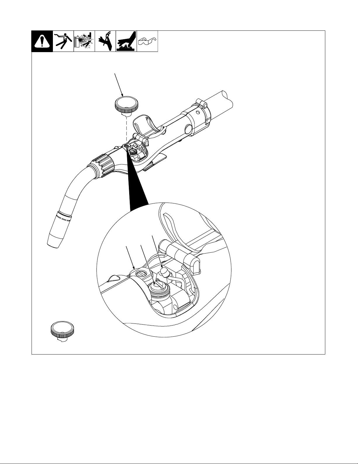
4-2. Drive Roll Removal/Installation
1
1 Drive Roll Removal Tool
P/N 215676
2 Drive Roll
3 Idler Roll
4 Cam Lever
. The gun handles do not need
to be removed for access to
the drive or idler rolls.
Drive Roll Removal/Installation
. For insulated drive roll kits see
Section 8 Options and Acces-
sories.
Pull cam lever away from idler roll.
This relieves pressure against the
the drive roll.
Align drive roll removal tool over
the flats of the drive roll as shown.
Hold the gun with one hand or on a
table top, with the other hand give
the removal tool a quick snap-turn
clockwise direction.
Once the drive roll is loose, continue to spin drive roll in the clockwise
direction to remove the drive roll
from the gun.
Install a new drive roll on the lefthand threaded shaft. The drive roll
will self-tighten when it is feeding
wire.
Close top cover.
Tools Needed:
4
3
2
803 871-A / 803 872-A
OM-1500-17 Page 7
Page 12
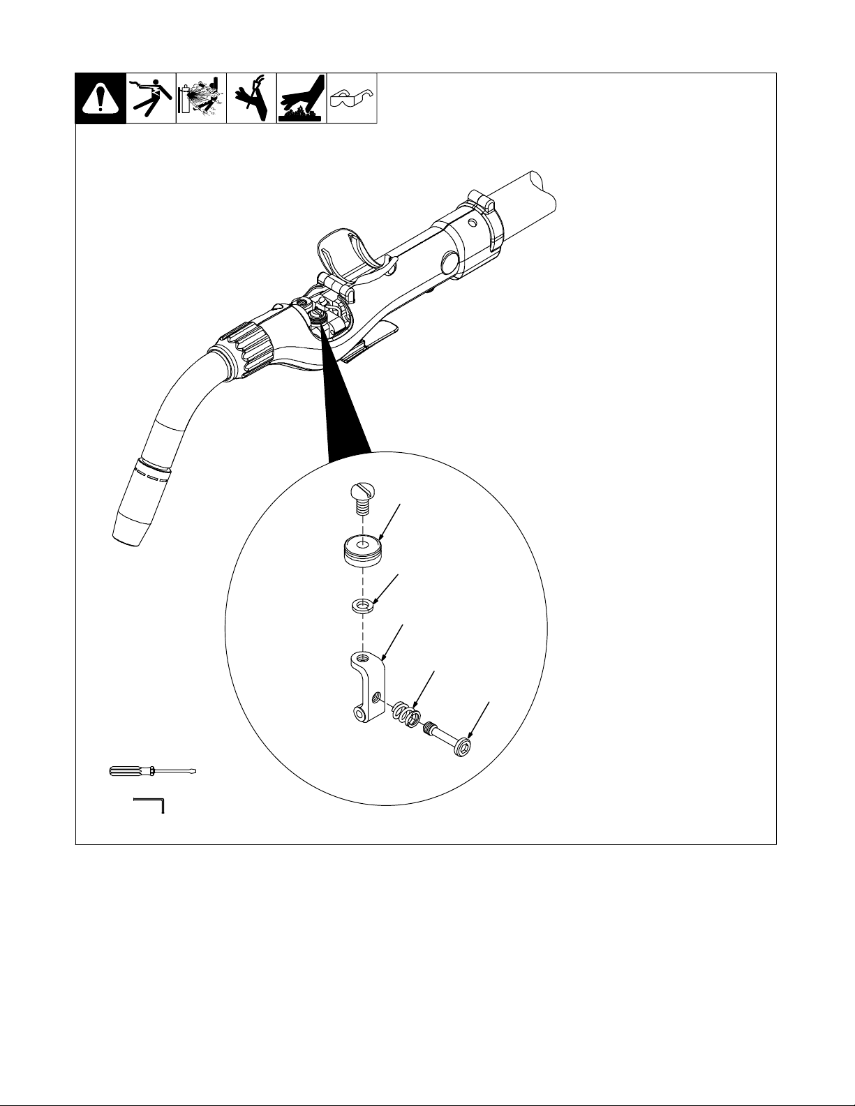
4-3. Idler Roll Removal/Installation
1 Idler Roll
2 Lockwasher
3 Idler Arm
4 Spring
5 Idler Screw
. The gun handles do not need
to be removed for access to
the drive or idler rolls.
Idler Roll Removal/Installation
Using a slot type screwdriver,
loosen idler screw, taking care not
to lose lock washer under idler roll.
Insert new idler roll and lock washer onto screw, insuring that idler
groove is toward top and lock
washer is beneath.
. Lock washer must be under
idler roll or it will not turn freely.
Tighten screw until tight.
Close top cover.
Tools Needed:
1
2
3
4
5
803 871-A / 803 872-A
OM-1500-17 Page 8
Page 13
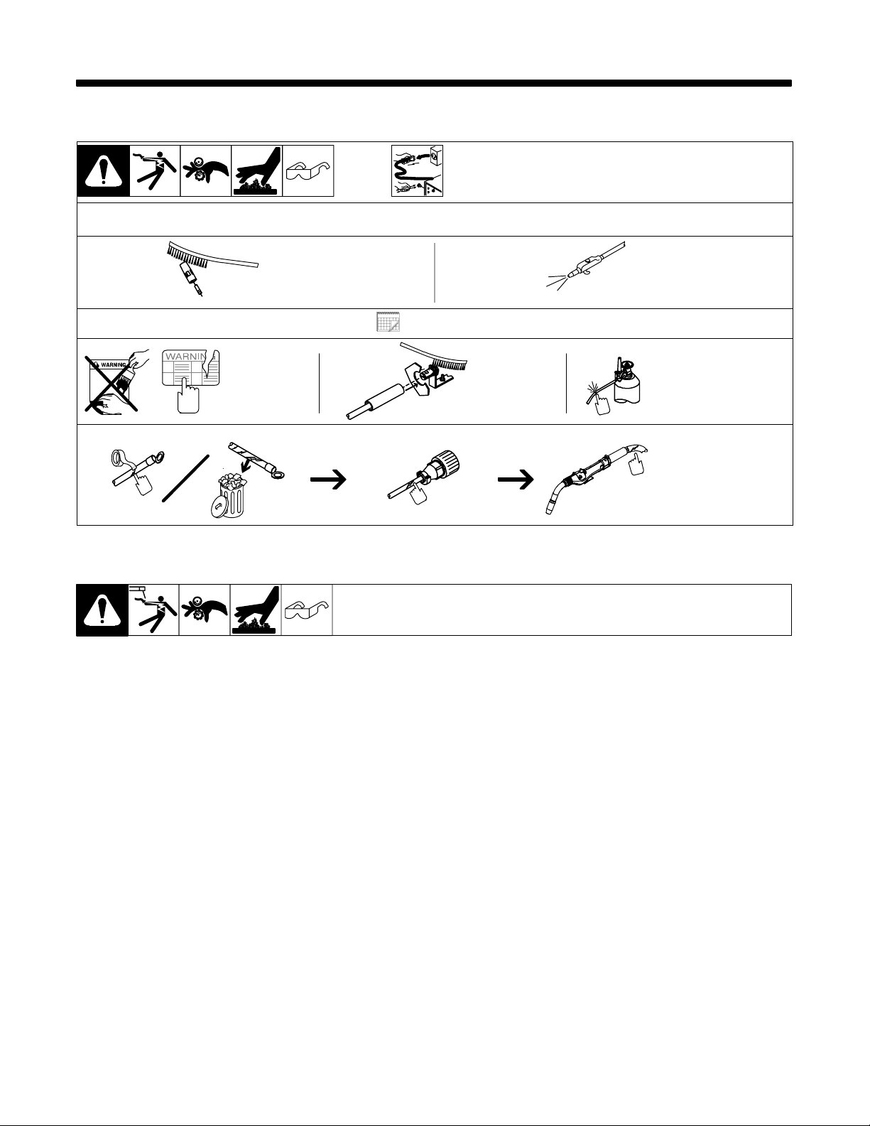
SECTION 5 − MAINTENANCE & TROUBLESHOOTING
5-1. Routine Maintenance
Clean
Nozzle
And Check
Contact Tip
Replace
Damaged Or
Unreadable
Labels
5-2. Troubleshooting Guide
Y Disconnect power
before maintaining.
Each Spool Of Wire
3 Months
Clean And
Tighten
Terminals
Weld
. Maintain more often
during severe conditions.
Blow Out Gun
Casing
Replace Damaged
Gas Hose
Repair Or Replace
Cracked Cables
And Cords
Y Disconnect power before troubleshooting.
To aid in troubleshooting problems with your welding equipment, it is best to understand the basic theory of operation
for this Push-Pull System. The push motor in the feeder runs at a fast, constant speed, but has very low torque. It
is always trying to feed more wire than the gun motor wants, and when the motor gets all it wants, it slows the push
motor, preventing a bird’s nest. Because of the low torque produced by the push motor, a brake system rather than
drag tension is used to prevent wire overrun when the motor stops. The drag adjustment in the feeder is used simply
to keep the wire slightly taut, to prevent wire overrun while feeding wire.
The high torque 24VDC gun motor is controlled by a solid state speed control located in the feeder, and a pot located
in the gun. The gun motor, potentiometer, and micro switch are connected to the cabinet/control box via a control cable
and Amphenol connector. If this cable becomes damaged, a variety of symptoms can occur, depending on which
wire(s) break. To test, check each wire for continuity and shorts.
Remember, the micro switch in the gun activates both the push motor and gun motor circuits in the cabinet. Therefore,
if the push motor and brake solenoid operate, but the gun does not, look more toward the gun motor’s 24VDC circuits,
speed control, control cable, or the gun motor. If nothing operates, look more toward the push motor’s input, micro
switch leads, or micro switch.
OM-1500-17 Page 9
Page 14
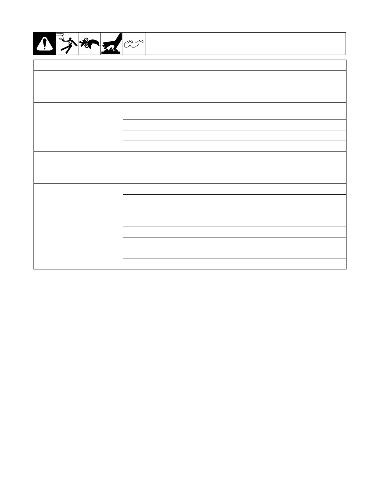
5-3. Troubleshooting Table
Trouble Remedy
Y Disconnect power before troubleshooting.
No wire feed at gun, feeder not operating. Check motor or brake solenoid.
No wire feed at gun, feeder operating
properly.
Wire feeds, but welding wire is not energized.
Wire feeds erratically.
Wire feeds one speed only.
Wire walks out of drive rolls.
Reset circuit breaker in feeder/control box. See feeder/control owner’s manual.
Replace micro-switch and test operation.
Check micro-switch wires for continuity.
Reset circuit breaker in feeder/control box and check for short in motor leads. See feeder/control owner’s
manual.
Check potentiometer with meter and replace if necessary.
Check motor and potentiometer wires for continuity.
See feeder/control owner’s manual.
Clean and tighten all power connections.
See feeder/control owner’s manual.
Check operation of welding power source.
Check conduit for wear and obstruction and replace if necessary.
Check contact tip for correct size and replace if necessary.
Check for missing or damaged lock washer under idler roll.
Check potentiometer with meter and replace if necessary.
Check continuity of welding gun wire feed speed potentiometer and replace if necessary.
See feeder/control owner’s manual.
Idler roll upside down, place groove in idler roll towards top.
Rear wire guide missing, replace wire guide.
OM-1500-17 Page 10
Page 15
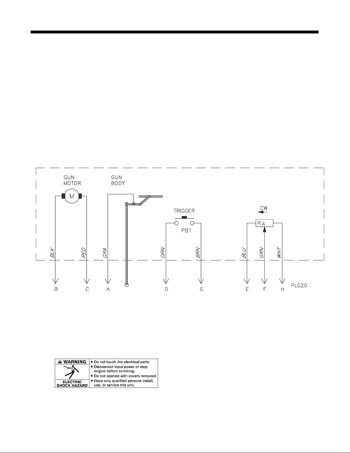
SECTION 6 − ELECTRICAL DIAGRAMS
Figure 6-1. Circuit Diagram For XR-A Python Gun
220 166-A
OM-1500-17 Page 11
Page 16
38
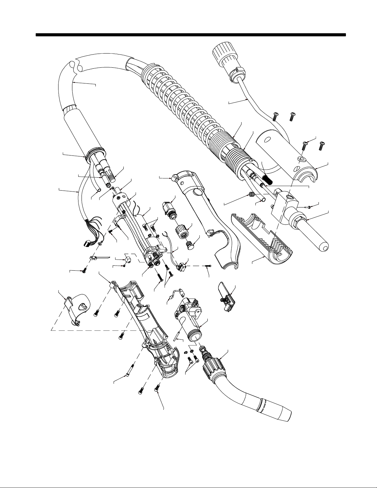
SECTION 7 − PARTS LIST
40
38
14
15
7
37
33
34
33
22
37
36
29
2
16
8
39
30
5
11
13
34
22
10
32
23
29
21
31
26
20
28
17
19
18
27
35
6
12
24
1
4
25
30
3
9
OM-1500-17 Page 12
30
Figure 7-1. XR -A Python 25 Ft.
803 875-C
Page 17

Item
No.
Part
No.
Description
Figure 7-1. XR -A Python 25 Ft.
1 220 688 Cam Idler Arm Assembly 1. . . . . . . . . . . . . . . . . . . . . . . . . . . . . . . . . . . . . . . . . . . . . . . . . . . . . . . . . . . .
2 220 689 Brazed Rear Body 1. . . . . . . . . . . . . . . . . . . . . . . . . . . . . . . . . . . . . . . . . . . . . . . . . . . . . . . . . . . . . . . . .
3 *215 668 Trigger Kit 1. . . . . . . . . . . . . . . . . . . . . . . . . . . . . . . . . . . . . . . . . . . . . . . . . . . . . . . . . . . . . . . . . . . . . . .
4 220 690 Front Body Assembly 1. . . . . . . . . . . . . . . . . . . . . . . . . . . . . . . . . . . . . . . . . . . . . . . . . . . . . . . . . . . . . . .
5 220 691 Pot Knob Assembly 1. . . . . . . . . . . . . . . . . . . . . . . . . . . . . . . . . . . . . . . . . . . . . . . . . . . . . . . . . . . . . . . .
6 *215 671 Micro Switch Kit 1. . . . . . . . . . . . . . . . . . . . . . . . . . . . . . . . . . . . . . . . . . . . . . . . . . . . . . . . . . . . . . . . . .
7 220 692 Lead Assembly Boot 1. . . . . . . . . . . . . . . . . . . . . . . . . . . . . . . . . . . . . . . . . . . . . . . . . . . . . . . . . . . . . . .
8 *215 670 Pot Assembly Kit 1. . . . . . . . . . . . . . . . . . . . . . . . . . . . . . . . . . . . . . . . . . . . . . . . . . . . . . . . . . . . . . . . .
9 215 687 Barrel 60° 1. . . . . . . . . . . . . . . . . . . . . . . . . . . . . . . . . . . . . . . . . . . . . . . . . . . . . . . . . . . . . . . . . . . . . . . .
10 220 693 Power Pin Assembly 1. . . . . . . . . . . . . . . . . . . . . . . . . . . . . . . . . . . . . . . . . . . . . . . . . . . . . . . . . . . . . . .
11 145 217 Screw K40 x 12 4. . . . . . . . . . . . . . . . . . . . . . . . . . . . . . . . . . . . . . . . . . . . . . . . . . . . . . . . . . . . . . . . . . . .
12 189 812 Housing, Power Pin Handle - Right 1. . . . . . . . . . . . . . . . . . . . . . . . . . . . . . . . . . . . . . . . . . . . . . . . . . .
13 189 811 Housing, Power Pin Handle - Left 1. . . . . . . . . . . . . . . . . . . . . . . . . . . . . . . . . . . . . . . . . . . . . . . . . . . .
14 203 562 Strain Relief Spring 1. . . . . . . . . . . . . . . . . . . . . . . . . . . . . . . . . . . . . . . . . . . . . . . . . . . . . . . . . . . . . . . .
15 203 560 Spring Retainer 1. . . . . . . . . . . . . . . . . . . . . . . . . . . . . . . . . . . . . . . . . . . . . . . . . . . . . . . . . . . . . . . . . . . .
16 220 694 Motor 1. . . . . . . . . . . . . . . . . . . . . . . . . . . . . . . . . . . . . . . . . . . . . . . . . . . . . . . . . . . . . . . . . . . . . . . . . . . .
17 220 695 O-Ring 2-007 Buna N 6. . . . . . . . . . . . . . . . . . . . . . . . . . . . . . . . . . . . . . . . . . . . . . . . . . . . . . . . . . . . . .
18 220 696 Screw FH Phil 82 4-40 x 3/8 SST 2. . . . . . . . . . . . . . . . . . . . . . . . . . . . . . . . . . . . . . . . . . . . . . . . . . . .
19 220 697 Screw FH Phil 82 4-40 x 5/8 SST 1. . . . . . . . . . . . . . . . . . . . . . . . . . . . . . . . . . . . . . . . . . . . . . . . . . . .
20 220 698 Screw Button 4-40 x 3/16 ST 2. . . . . . . . . . . . . . . . . . . . . . . . . . . . . . . . . . . . . . . . . . . . . . . . . . . . . . . .
21 220 699 Set Screw #4-40 x 1/8 SST 1. . . . . . . . . . . . . . . . . . . . . . . . . . . . . . . . . . . . . . . . . . . . . . . . . . . . . . . . .
22 220 700 Set Screw Mod 2. . . . . . . . . . . . . . . . . . . . . . . . . . . . . . . . . . . . . . . . . . . . . . . . . . . . . . . . . . . . . . . . . . . .
23 220 702 Screw PH Phil 4-40 x 5/16 SST 1. . . . . . . . . . . . . . . . . . . . . . . . . . . . . . . . . . . . . . . . . . . . . . . . . . . . . .
24 220 703 Screw SHC 1-72 x 3/8 1. . . . . . . . . . . . . . . . . . . . . . . . . . . . . . . . . . . . . . . . . . . . . . . . . . . . . . . . . . . . . .
25 220 704 Dowel Pin 3/32 x 7/8 SST 1. . . . . . . . . . . . . . . . . . . . . . . . . . . . . . . . . . . . . . . . . . . . . . . . . . . . . . . . . . .
26 220 705 Wire Guide 1. . . . . . . . . . . . . . . . . . . . . . . . . . . . . . . . . . . . . . . . . . . . . . . . . . . . . . . . . . . . . . . . . . . . . . . .
27 220 707 Hex Screw 3/8 -20 x 3/8 1. . . . . . . . . . . . . . . . . . . . . . . . . . . . . . . . . . . . . . . . . . . . . . . . . . . . . . . . . . . .
28 220 712 Motor Strap 1. . . . . . . . . . . . . . . . . . . . . . . . . . . . . . . . . . . . . . . . . . . . . . . . . . . . . . . . . . . . . . . . . . . . . . .
29 *215 665 Handle Kit Right/Left (Includes) 1. . . . . . . . . . . . . . . . . . . . . . . . . . . . . . . . . . . . . . . . . . . . . . . . . . . . .
30 220 701 Screw SHC 6-32 x 3/8 9. . . . . . . . . . . . . . . . . . . . . . . . . . . . . . . . . . . . . . . . . . . . . . . . . . . . . . . . . . . . . .
31 220 706 Shoulder Screw 1/8 x 4-40 1. . . . . . . . . . . . . . . . . . . . . . . . . . . . . . . . . . . . . . . . . . . . . . . . . . . . . . . . . .
32 215 666 Molded Door 1. . . . . . . . . . . . . . . . . . . . . . . . . . . . . . . . . . . . . . . . . . . . . . . . . . . . . . . . . . . . . . . . . . . . . . .
33 215 698 Gas Hose 1. . . . . . . . . . . . . . . . . . . . . . . . . . . . . . . . . . . . . . . . . . . . . . . . . . . . . . . . . . . . . . . . . . . . . . . . .
34 *215 695 Conduit 1. . . . . . . . . . . . . . . . . . . . . . . . . . . . . . . . . . . . . . . . . . . . . . . . . . . . . . . . . . . . . . . . . . . . . . . . . .
35 220 713 Tube Insulation 9 AWG, Clear 0.30 FT. . . . . . . . . . . . . . . . . . . . . . . . . . . . . . . . . . . . . . . . . . . . . . . . . . . .
36 220 714 Cap Plug 0.218 ID x 0.50 LG 1. . . . . . . . . . . . . . . . . . . . . . . . . . . . . . . . . . . . . . . . . . . . . . . . . . . . . . . .
37 215 702 Power Cable 1. . . . . . . . . . . . . . . . . . . . . . . . . . . . . . . . . . . . . . . . . . . . . . . . . . . . . . . . . . . . . . . . . . . . . .
38 215 701 Control Cable 1. . . . . . . . . . . . . . . . . . . . . . . . . . . . . . . . . . . . . . . . . . . . . . . . . . . . . . . . . . . . . . . . . . . . .
39 141 694 Screw, Set 312-18x .37 Conept Sch Stl Pln 1. . . . . . . . . . . . . . . . . . . . . . . . . . . . . . . . . . . . . . . . . . . .
40 215 703 25Ft Snake Skin, Cvr For Torch Leads 1. . . . . . . . . . . . . . . . . . . . . . . . . . . . . . . . . . . . . . . . . . . . . . . .
*Recommended Spare Parts.
Quantity
OM-1500-17 Page 13
Page 18
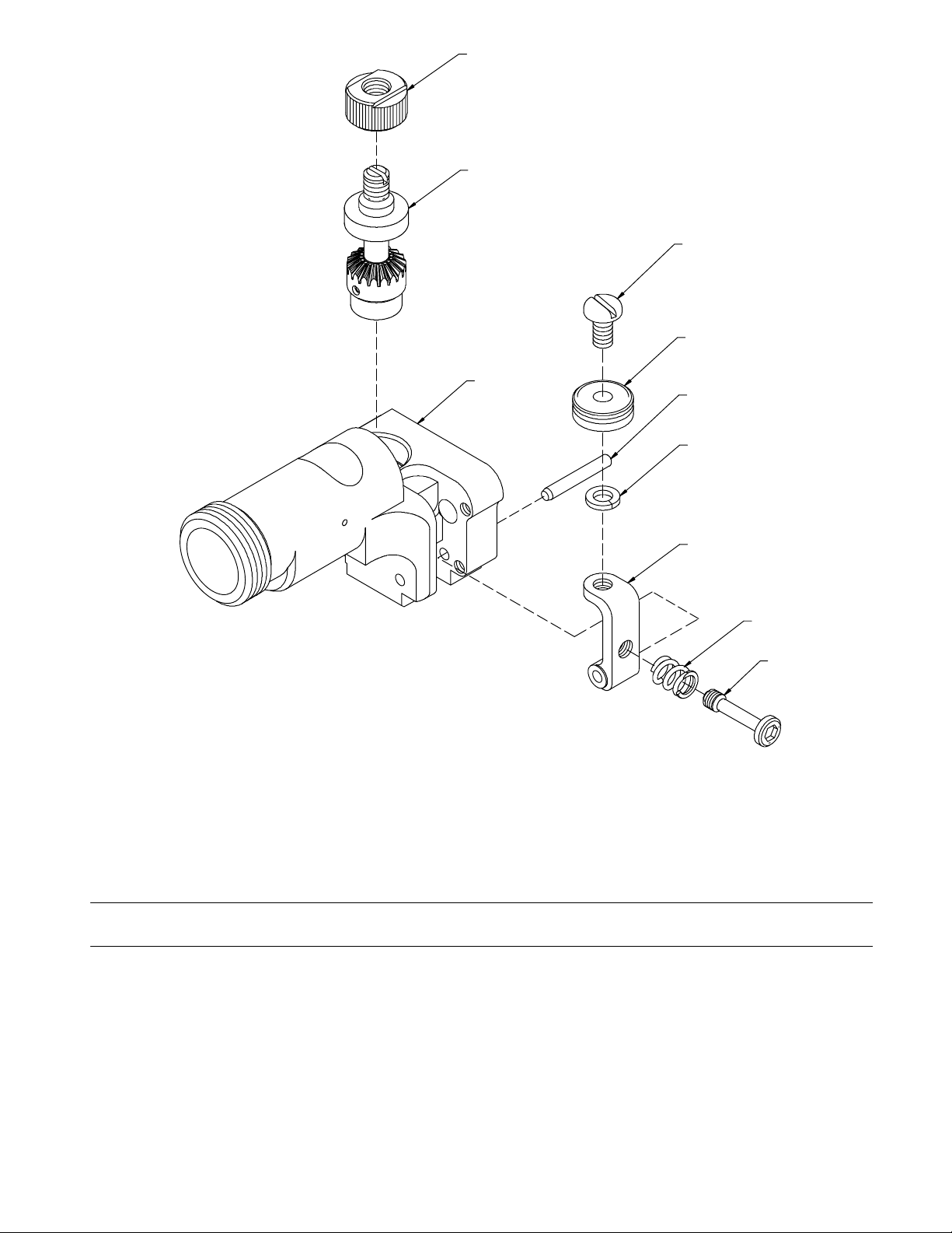
10
1
7
9
2
4
8
6
3
5
803 876-A
Figure 7-2. Front Body Assembly
Item
No.
Part
No.
Description
Figure 7-2. Front Body Assembly
1 220 715 Output Shaft Assembly 1. . . . . . . . . . . . . . . . . . . . . . . . . . . . . . . . . . . . . . . . . . . . . . . . . . . . . . . . . . . . .
2 220 716 Body Assembly 1. . . . . . . . . . . . . . . . . . . . . . . . . . . . . . . . . . . . . . . . . . . . . . . . . . . . . . . . . . . . . . . . . . . .
3 220 719 0.29 x 0.047 x 0.32 Comp. Spring 1. . . . . . . . . . . . . . . . . . . . . . . . . . . . . . . . . . . . . . . . . . . . . . . . . . . .
4 220 720 1/8 x 7/8 SST Dowel Pin 1. . . . . . . . . . . . . . . . . . . . . . . . . . . . . . . . . . . . . . . . . . . . . . . . . . . . . . . . . . . .
5 220 721 Idler Adjusting Screw 1. . . . . . . . . . . . . . . . . . . . . . . . . . . . . . . . . . . . . . . . . . . . . . . . . . . . . . . . . . . . . . .
6 220 722 Idler Arm 1. . . . . . . . . . . . . . . . . . . . . . . . . . . . . . . . . . . . . . . . . . . . . . . . . . . . . . . . . . . . . . . . . . . . . . . . .
215 674 Idler Roll Kit (Includes) 1. . . . . . . . . . . . . . . . . . . . . . . . . . . . . . . . . . . . . . . . . . . . . . . . . . . . . . . . . . . . . . . . .
7 *220 717 10-24 x 3/8 PH Screw 1. . . . . . . . . . . . . . . . . . . . . . . . . . . . . . . . . . . . . . . . . . . . . . . . . . . . . . . . . . . . .
8 *220 718 #10 Lockwasher 1. . . . . . . . . . . . . . . . . . . . . . . . . . . . . . . . . . . . . . . . . . . . . . . . . . . . . . . . . . . . . . . . . .
9 *220 723 Idler Wire Feed Assembly 1. . . . . . . . . . . . . . . . . . . . . . . . . . . . . . . . . . . . . . . . . . . . . . . . . . . . . . . . . .
10 *215 672 Drive Roll 1. . . . . . . . . . . . . . . . . . . . . . . . . . . . . . . . . . . . . . . . . . . . . . . . . . . . . . . . . . . . . . . . . . . . . . . .
*Recommended Spare Parts.
OM-1500-17 Page 14
Quantity
Page 19
3
10
6
8
9
7
2
1
5
4
803 878-B
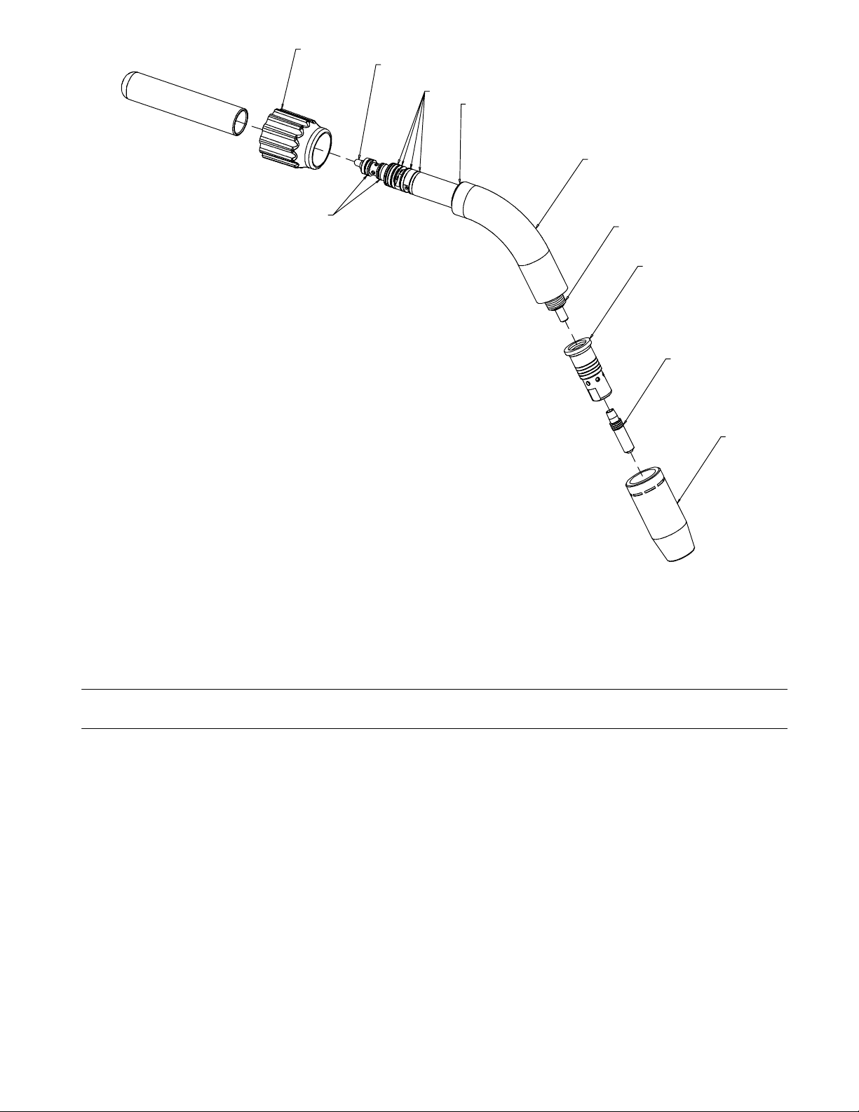
Figure 7-3. Barrel Assembly
Item
No.
Part
No.
Description
Figure 7-3. Barrel Assembly
215 687 Barrel Assy, Air/Water Cooled 60 Deg (Includes) 1. . . . . . . . . . . . . . . . . . . . . . . . . . . . . . . . . . . . . . . . . .
1 *206 195 Diffuser, 1/8 Tip Recess 1. . . . . . . . . . . . . . . . . . . . . . . . . . . . . . . . . . . . . . . . . . . . . . . . . . . . . . . . . . . .
2 220 724 Assy Barrel Bend 1. . . . . . . . . . . . . . . . . . . . . . . . . . . . . . . . . . . . . . . . . . . . . . . . . . . . . . . . . . . . . . . . . .
3 220 725 Assy Taper Lock Barrel 1. . . . . . . . . . . . . . . . . . . . . . . . . . . . . . . . . . . . . . . . . . . . . . . . . . . . . . . . . . . . .
4 *198 855 Nozzle, Copper, 5/8 in Orifice 1. . . . . . . . . . . . . . . . . . . . . . . . . . . . . . . . . . . . . . . . . . . . . . . . . . . . . . .
5 *206 189 .052 Heavy Duty FasTip 1. . . . . . . . . . . . . . . . . . . . . . . . . . . . . . . . . . . . . . . . . . . . . . . . . . . . . . . . . . . .
6 215 693 O-Ring, 0.489 Id x 0.629 Od 4. . . . . . . . . . . . . . . . . . . . . . . . . . . . . . . . . . . . . . . . . . . . . . . . . . . . . . . . .
7 215 694 O-Ring, 0.301 Id x 0.070 Wt 2. . . . . . . . . . . . . . . . . . . . . . . . . . . . . . . . . . . . . . . . . . . . . . . . . . . . . . . . .
8 220 726 Retaining Ring 1. . . . . . . . . . . . . . . . . . . . . . . . . . . . . . . . . . . . . . . . . . . . . . . . . . . . . . . . . . . . . . . . . . . . .
9 220 727 Barrel Insulator 1. . . . . . . . . . . . . . . . . . . . . . . . . . . . . . . . . . . . . . . . . . . . . . . . . . . . . . . . . . . . . . . . . . . .
10 *215 689 Liner, Teflon Package - Used With Aluminum Wire A/R. . . . . . . . . . . . . . . . . . . . . . . . . . . . . . . . . . . .
10 215 692 Liner, Spiral Steel - Used With Steel and Hard Wires A/R. . . . . . . . . . . . . . . . . . . . . . . . . . . . . . . . . . .
*Recommended Spare Parts.
Quantity
OM-1500-17 Page 15
Page 20

Item
No.
Part
No.
Description
Figure 7-3. Barrel Assembly Consumables Flowchart
Nozzles
4 ♦176 238 Nozzle, Spot Flat 1. . . . . . . . . . . . . . . . . . . . . . . . . . . . . . . . . . . . . . . . . . . . . . . . . . . . . . . . . . . . . . . .
4 ♦176 240 Nozzle, Spot Inside Corner 1. . . . . . . . . . . . . . . . . . . . . . . . . . . . . . . . . . . . . . . . . . . . . . . . . . . . . . . .
4 ♦176 242 Nozzle, Spot Outside Corner 1. . . . . . . . . . . . . . . . . . . . . . . . . . . . . . . . . . . . . . . . . . . . . . . . . . . . . .
4 199 610 Nozzle, Screw On Brass 1/2 In Orifice 1. . . . . . . . . . . . . . . . . . . . . . . . . . . . . . . . . . . . . . . . . . . . . . . .
4 199 611 Nozzle, Screw On Brass 3/4 In Orifice Straight 1. . . . . . . . . . . . . . . . . . . . . . . . . . . . . . . . . . . . . . . . .
4 199 612 Nozzle, Screw On Brass 3/4 In Orifice Straight Heavy Duty 1. . . . . . . . . . . . . . . . . . . . . . . . . . . . . .
4 199 613 Nozzle, Screw On Brass 5/8 In Orifice 1. . . . . . . . . . . . . . . . . . . . . . . . . . . . . . . . . . . . . . . . . . . . . . . .
4 199 614 Nozzle, Screw On Brass 5/8 In Orifice Heavy Duty 1. . . . . . . . . . . . . . . . . . . . . . . . . . . . . . . . . . . . .
4 199 615 Nozzle, Screw On Copper 1/2 In Orifice 1. . . . . . . . . . . . . . . . . . . . . . . . . . . . . . . . . . . . . . . . . . . . . . .
4 199 616 Nozzle, Screw On Copper 3/4 In Orifice 1. . . . . . . . . . . . . . . . . . . . . . . . . . . . . . . . . . . . . . . . . . . . . . .
4 199 617 Nozzle, Screw On Copper 3/4 In Orifice Heavy Duty 1. . . . . . . . . . . . . . . . . . . . . . . . . . . . . . . . . . . .
4 198 855 Nozzle, Screw On Copper 5/8 In Orifice (Standard On 300 & 400 . . . . . . . . . . . . . . .
Amp Models) 1. . . . . . . . . . . . . . . . . . . . . . . . . . . . . . . . . . . . . . . . . . . . . . . . . . . . . . .
4 199 618 Nozzle, Screw On Copper 5/8 In Orifice Heavy Duty . . . . . . . . . . . . . . .
(Standard On 500 & 600 Amp Models) 1. . . . . . . . . . . . . . . . . . . . . . . . . . . . . . . . .
4 207 313 Nozzle, Screw On Copper 5/8 In Orifice 15/16 Od 1. . . . . . . . . . . . . . . . . . . . . . . . . . . . . . . . . . . . . .
4 ♦♦209 035 Nozzle, Screw On Copper 3/8 In Orifice Tapered 1. . . . . . . . . . . . . . . . . . . . . . . . . . . . . . . . . . . .
4 ♦♦209 036 Nozzle, Screw On Copper 1/2 In Orifice Tapered 1. . . . . . . . . . . . . . . . . . . . . . . . . . . . . . . . . . . .
Quantity
Heavy Duty FasTiptContact Tips*
5 206 186 .035 in (0.9 mm) / .030 in (0.8 mm) Aluminum Wire 1. . . . . . . . . . . . . . . . . . . . . . . . . . . . . . . . . . . . .
5 206 187 .040 in (1.0 mm) / .035 in (0.9 mm) Aluminum Wire 1. . . . . . . . . . . . . . . . . . . . . . . . . . . . . . . . . . . . .
5 206 188 .045 in (1.2 mm) / .040 in (1.0 mm) Aluminum Wire 1. . . . . . . . . . . . . . . . . . . . . . . . . . . . . . . . . . . . .
5 206 189 .052 in (1.3 mm) or 3/64 in (1.2 mm) Aluminum Wire 1. . . . . . . . . . . . . . . . . . . . . . . . . . . . . . . . . . . .
5 206 190 1/16 in (1.6 mm) 1. . . . . . . . . . . . . . . . . . . . . . . . . . . . . . . . . . . . . . . . . . . . . . . . . . . . . . . . . . . . . . . . . . .
5 206 191 .068 in (1.7 mm) or 1/16 in (1.6 mm) Aluminum Wire 1. . . . . . . . . . . . . . . . . . . . . . . . . . . . . . . . . . . .
Tapered FasTipt Contact Tips*
5 209 026 .035 in (0.9 mm) / .030 in (0.8 mm) Aluminum Wire 1. . . . . . . . . . . . . . . . . . . . . . . . . . . . . . . . . . . . .
5 209 027 .045 in (1.2 mm) / .035 in (0.9 mm) Aluminum Wire 1. . . . . . . . . . . . . . . . . . . . . . . . . . . . . . . . . . . . .
5 209 028 3/64 in (1.2 mm) 1. . . . . . . . . . . . . . . . . . . . . . . . . . . . . . . . . . . . . . . . . . . . . . . . . . . . . . . . . . . . . . . . . . .
5 209 029 .052 in (1.3 mm) 1. . . . . . . . . . . . . . . . . . . . . . . . . . . . . . . . . . . . . . . . . . . . . . . . . . . . . . . . . . . . . . . . . . .
5 209 030 1/16 in (1.6 mm) 1. . . . . . . . . . . . . . . . . . . . . . . . . . . . . . . . . . . . . . . . . . . . . . . . . . . . . . . . . . . . . . . . . . .
Gas Diffusers
1 206 195 1/8 In Tip Recess − For Heavy Duty FasTip Contact Tips. . . . . . . . . . . . . . .
(Standard On All Guns) 1. . . . . . . . . . . . . . . . . . . . . . . . . . . . . . . . . . . . . . . . . . . . . .
1 210 664 1/4 In Tip Recess − For Heavy Duty FasTip Contact Tips 1. . . . . . . . . . . . . . . . . . . . . . . . . . . . . . . .
1 206 196 Flush Tip − For Heavy Duty FasTip Contact Tips 1. . . . . . . . . . . . . . . . . . . . . . . . . . . . . . . . . . . . . . .
♦Requires diffuser 209099, used with any heavy duty FasTipt contact tip.
♦♦Requires diffuser 206195, 206196 or 210664, used with any tapered FasTipt contact tip.
BE SURE TO PROVIDE MODEL WHEN ORDERING REPLACEMENT PARTS.
To maintain the factory original performance of your equipment, use only Manufacturer’s Suggested
Replacement Parts. Model is required when ordering parts from your local distributor.
OM-1500-17 Page 16
Page 21
4
9
5
6
7
8
1
2
3
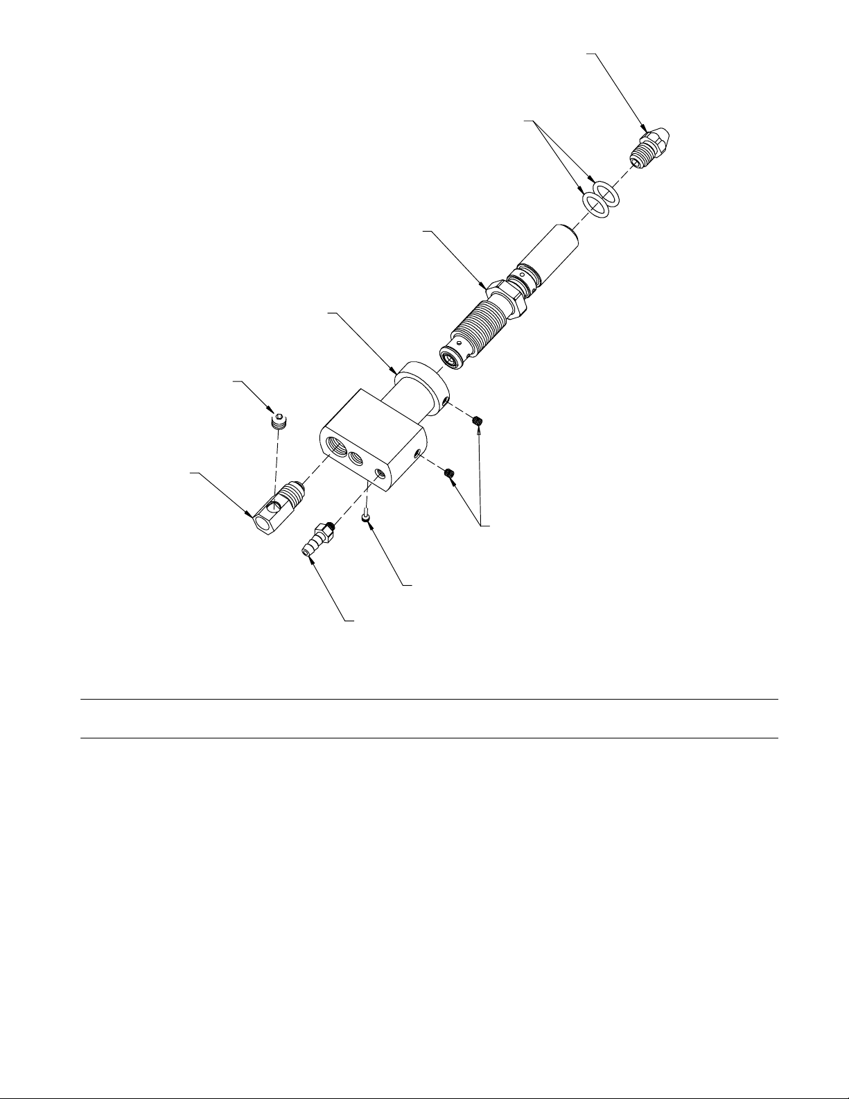
Figure 7-4. Power/Gas Connector
Item
No.
Part
No.
Description
Figure 7-4. Power/Gas Connector
1 602 172 Set Screw, 10-32 x 18 2. . . . . . . . . . . . . . . . . . . . . . . . . . . . . . . . . . . . . . . . . . . . . . . . . . . . . . . . . . . . . .
2 220 700 Set Screw Mod 1. . . . . . . . . . . . . . . . . . . . . . . . . . . . . . . . . . . . . . . . . . . . . . . . . . . . . . . . . . . . . . . . . . . .
3 202 513 Gas Hose Fitting 1. . . . . . . . . . . . . . . . . . . . . . . . . . . . . . . . . . . . . . . . . . . . . . . . . . . . . . . . . . . . . . . . . . .
4 226 445 Guide, Wire Outlet .030−1/16 1. . . . . . . . . . . . . . . . . . . . . . . . . . . . . . . . . . . . . . . . . . . . . . . . . . . . . . . .
5 193 896 Power Pin Assembly 4. . . . . . . . . . . . . . . . . . . . . . . . . . . . . . . . . . . . . . . . . . . . . . . . . . . . . . . . . . . . . . .
6 220 729 Power Gas Connector 2. . . . . . . . . . . . . . . . . . . . . . . . . . . . . . . . . . . . . . . . . . . . . . . . . . . . . . . . . . . . . .
7 141 694 Set Screw, 5/16-18 x 0.37 1. . . . . . . . . . . . . . . . . . . . . . . . . . . . . . . . . . . . . . . . . . . . . . . . . . . . . . . . . . .
8 137 495 Power Weld Fitting 1. . . . . . . . . . . . . . . . . . . . . . . . . . . . . . . . . . . . . . . . . . . . . . . . . . . . . . . . . . . . . . . . .
9 079 974 O-Ring, 0.5 Id 2. . . . . . . . . . . . . . . . . . . . . . . . . . . . . . . . . . . . . . . . . . . . . . . . . . . . . . . . . . . . . . . . . . . . .
803 877-B
Quantity
OM-1500-17 Page 17
Page 22

SECTION 8 − OPTIONS AND ACCESSORIES
Insulated Drive Roll Kits
Used to prevent preheating of the wire which may soften it and clog the liner. This picking up of current at the drive rolls
rather than at the contact tip is usually not a problem unless using too large of a contact tip or excessively oxidized
aluminum wire.
Insulated groove drive roll kits include insulated drive roll and idler roll assembly.
Wire Size Part Number
0.030 (0.8mm) 215677
0.035 (0.9mm) 215678
0.045 (1.2mm) 215681
0.062 (1.6mm) 215684
OM-1500-17 Page 18
Page 23

Warranty Questions?
Call
1-800-4-A-MILLER
for your local
Miller distributor.
Your distributor also gives
you ...
Service
You always get the fast,
reliable response you
need. Most replacement
parts can be in your
hands in 24 hours.
Support
Need fast answers to the
tough welding questions?
Contact your distributor.
The expertise of the
distributor and Miller is
there to help you, every
step of the way.
Effective January 1, 2005
(Equipment with a serial number preface of “LF” or newer)
This limited warranty supersedes all previous Miller warranties and is exclusive with no other
LIMITED WARRANTY − Subject to the terms and conditions
below, Miller Electric Mfg. Co., Appleton, Wisconsin, warrants to
its original retail purchaser that new Miller equipment sold after
the effective date of this limited warranty is free of defects in
material and workmanship at the time it is shipped by Miller.
THIS WARRANTY IS EXPRESSLY IN LIEU OF ALL OTHER
WARRANTIES, EXPRESS OR IMPLIED, INCLUDING THE
WARRANTIES OF MERCHANTABILITY AND FITNESS.
Within the warranty periods listed below, Miller will repair or
replace any warranted parts or components that fail due to such
defects in material or workmanship. Miller must be notified in
writing within thirty (30) days of such defect or failure, at which
time Miller will provide instructions on the warranty claim
procedures to be followed.
Miller shall honor warranty claims on warranted equipment
listed below in the event of such a failure within the warranty
time periods. All warranty time periods start on the date that the
equipment was delivered to the original retail purchaser, or one
year after the equipment is sent to a North American distributor
or eighteen months after the equipment is sent to an
International distributor.
1. 5 Years Parts — 3 Years Labor
* Original main power rectifiers
* Inverters (input and output rectifiers only)
2. 3 Years — Parts and Labor
* Transformer/Rectifier Power Sources
* Plasma Arc Cutting Power Sources
* Semi-Automatic and Automatic Wire Feeders
* Inverter Power Sources (Unless Otherwise Stated)
* Water Coolant Systems (Integrated)
* Intellitig
* Maxstar 150
* Engine Driven Welding Generators
(NOTE: Engines are warranted separately by
the engine manufacturer.)
3. 1 Year — Parts and Labor Unless Specified
* DS-2 Wire Feeder
* Motor Driven Guns (w/exception of Spoolmate
Spoolguns)
* Process Controllers
* Positioners and Controllers
* Automatic Motion Devices
* RFCS Foot Controls
* Induction Heating Power Sources and Coolers
* Water Coolant Systems (Non-Integrated)
* Flowgauge and Flowmeter Regulators (No Labor)
* HF Units
* Grids
* Maxstar 85, 140
* Spot Welders
* Load Banks
* Arc Stud Power Sources & Arc Stud Guns
* Racks
* Running Gear/Trailers
* Plasma Cutting Torches (except APT & SAF
Models)
* Field Options
(NOTE: Field options are covered under True
Blue® for the remaining warranty period of the
product they are installed in, or for a minimum of
one year — whichever is greater.)
4. 6 Months — Batteries
5. 90 Days — Parts
* MIG Guns/TIG Torches
guarantees or warranties expressed or implied.
* Induction Heating Coils and Blankets
* APT & SAF Model Plasma Cutting Torches
* Remote Controls
* Accessory Kits
* Replacement Parts (No labor)
* Spoolmate Spoolguns
* Canvas Covers
Miller’s True Blue® Limited Warranty shall not apply to:
1. Consumable components; such as contact tips,
cutting nozzles, contactors, brushes, slip rings,
relays or parts that fail due to normal wear. (Exception:
brushes, slip rings, and relays are covered on Bobcat,
Trailblazer, and Legend models.)
2. Items furnished by Miller, but manufactured by others,
such as engines or trade accessories. These items are
covered by the manufacturer’s warranty, if any.
3. Equipment that has been modified by any party other than
Miller, or equipment that has been improperly installed,
improperly operated or misused based upon industry
standards, or equipment which has not had reasonable
and necessary maintenance, or equipment which has
been used for operation outside of the specifications for the
equipment.
MILLER PRODUCTS ARE INTENDED FOR PURCHASE AND
USE BY COMMERCIAL/INDUSTRIAL USERS AND
PERSONS TRAINED AND EXPERIENCED IN THE USE AND
MAINTENANCE OF WELDING EQUIPMENT.
In the event of a warranty claim covered by this warranty, the
exclusive remedies shall be, at Miller’s option: (1) repair; or (2)
replacement; or, where authorized in writing by Miller in
appropriate cases, (3) the reasonable cost of repair or
replacement at an authorized Miller service station; or (4)
payment of or credit for the purchase price (less reasonable
depreciation based upon actual use) upon return of the goods at
customer’s risk and expense. Miller’s option of repair or
replacement will be F.O.B., Factory at Appleton, Wisconsin, or
F.O.B. at a Miller authorized service facility as determined by
Miller. Therefore no compensation or reimbursement for
transportation costs of any kind will be allowed.
TO THE EXTENT PERMITTED BY LAW, THE REMEDIES
PROVIDED HEREIN ARE THE SOLE AND EXCLUSIVE
REMEDIES. IN NO EVENT SHALL MILLER BE LIABLE FOR
DIRECT, INDIRECT, SPECIAL, INCIDENTAL OR
CONSEQUENTIAL DAMAGES (INCLUDING LOSS OF
PROFIT), WHETHER BASED ON CONTRACT, TORT OR
ANY OTHER LEGAL THEORY.
ANY EXPRESS WARRANTY NOT PROVIDED HEREIN AND
ANY IMPLIED WARRANTY, GUARANTY OR
REPRESENTATION AS TO PERFORMANCE, AND ANY
REMEDY FOR BREACH OF CONTRACT TORT OR ANY
OTHER LEGAL THEORY WHICH, BUT FOR THIS
PROVISION, MIGHT ARISE BY IMPLICATION, OPERATION
OF LAW, CUSTOM OF TRADE OR COURSE OF DEALING,
INCLUDING ANY IMPLIED WARRANTY OF
MERCHANTABILITY OR FITNESS FOR PARTICULAR
PURPOSE, WITH RESPECT TO ANY AND ALL EQUIPMENT
FURNISHED BY MILLER IS EXCLUDED AND DISCLAIMED
BY MILLER.
Some states in the U.S.A. do not allow limitations of how long an
implied warranty lasts, or the exclusion of incidental, indirect,
special or consequential damages, so the above limitation or
exclusion may not apply to you. This warranty provides specific
legal rights, and other rights may be available, but may vary
from state to state.
In Canada, legislation in some provinces provides for certain
additional warranties or remedies other than as stated herein,
and to the extent that they may not be waived, the limitations
and exclusions set out above may not apply. This Limited
Warranty provides specific legal rights, and other rights may be
available, but may vary from province to province.
miller_warr 1/05
Page 24
Owner’s Record
Please complete and retain with your personal records.
Model Name Serial/Style Number
Purchase Date (Date which equipment was delivered to original customer.)
Distributor
Address
City
State Zip
For Service
Contact a DISTRIBUTOR or SERVICE AGENCY near you.
Always provide Model Name and Serial/Style Number.
Contact your Distributor for:
Welding Supplies and Consumables
Options and Accessories
Personal Safety Equipment
Service and Repair
Replacement Parts
Training (Schools, Videos, Books)
Technical Manuals (Servicing Information
and Parts)
Circuit Diagrams
Welding Process Handbooks
To locate a Distributor or Service Agency visit
www.millerwelds.com or call 1-800-4-A-Miller
Miller Electric Mfg. Co.
An Illinois Tool Works Company
1635 West Spencer Street
Appleton, WI 54914 USA
International Headquarters−USA
USA Phone: 920-735-4505 Auto-Attended
USA & Canada FAX: 920-735-4134
International FAX: 920-735-4125
European Headquarters −
United Kingdom
Phone: 44 (0) 1204-593493
FAX: 44 (0) 1204-598066
www.MillerWelds.com
Contact the Delivering Carrier to:
File a claim for loss or damage during
shipment.
For assistance in filing or settling claims, contact
your distributor and/or equipment manufacturer’s
Transportation Department.
PRINTED IN USA © 2005 Miller Electric Mfg. Co. 1/05
 Loading...