

Miller XMT 304 Technical Manual
TM-180 670B September 2001
Eff. w/Serial Number KG13951 1
Processes
Multiprocess Welding
Description
Arc Welding Power Source
R
XMT 304
(400 Volt Models)
Visit our website at
www.MillerWelds.com

Declaration of Conformity For
European Community (CE) Products
Manufacturer’s Name: Miller Electric Mfg. Co.
Manufacturer’s Address: 1635 W. Spencer Street
Appleton, WI 54914 USA
Declares that the product: XMT 304
conforms to the following Directives and Standards:
Directives
Electromagnetic compatibility Directives: 89/336/EEC, 92/31/EEC
Low Voltage Directive: 73/23/EEC
Machinery Directives: 89/392/EEC, 91/368/EEC, 93/C 133/04, 93/68/EEC
Standards
Electromagnetic compatibility (EMC) Product standard for arc welding equipment:
EN50199: December 1995
Safety Requirements for Arc Welding Equipment part 1: EN 60974-1: 1989
Degrees of Protection provided by Enclosures (IP code): IEC 529: 1989
Insulation coordination for equipment within low-voltage systems:
Part 1: Principles, requirements and tests: IEC 664-1: 1992
European Contact: Danilo Fedolfi, Managing Director
MILLER Europe S.r.l.
Via Privata Iseo
20098 San Giuliano
Milanese, Italy
Telephone: 39(02)98290-1
Fax: 39(02)98281-552
dec_con1 10/95

TABLE OF CONTENTS
SECTION 1 – SAFETY PRECAUTIONS FOR SERVICING 1. . . . . . . . . . . . . . . . . . . . . . . . . . . . . . . . . . .
1-1. Symbol Usage 1. . . . . . . . . . . . . . . . . . . . . . . . . . . . . . . . . . . . . . . . . . . . . . . . . . . . . . . . . . . . . . . .
1-2. Servicing Hazards 1. . . . . . . . . . . . . . . . . . . . . . . . . . . . . . . . . . . . . . . . . . . . . . . . . . . . . . . . . . . .
1-3. EMF Information 2. . . . . . . . . . . . . . . . . . . . . . . . . . . . . . . . . . . . . . . . . . . . . . . . . . . . . . . . . . . . . .
SECTION 2 – DEFINITIONS 3. . . . . . . . . . . . . . . . . . . . . . . . . . . . . . . . . . . . . . . . . . . . . . . . . . . . . . . . . . . .
2-1. Manufacturer’s Warning Label Definitions 3. . . . . . . . . . . . . . . . . . . . . . . . . . . . . . . . . . . . . . . . .
2-2. Manufacturer’s Rating Labels 5. . . . . . . . . . . . . . . . . . . . . . . . . . . . . . . . . . . . . . . . . . . . . . . . . . .
2-3. Symbols And Definitions 6. . . . . . . . . . . . . . . . . . . . . . . . . . . . . . . . . . . . . . . . . . . . . . . . . . . . . . .
SECTION 3 – INSTALLATION 7. . . . . . . . . . . . . . . . . . . . . . . . . . . . . . . . . . . . . . . . . . . . . . . . . . . . . . . . . . .
3-1. Specifications 7. . . . . . . . . . . . . . . . . . . . . . . . . . . . . . . . . . . . . . . . . . . . . . . . . . . . . . . . . . . . . . . .
3-2. Duty Cycle And Overheating 7. . . . . . . . . . . . . . . . . . . . . . . . . . . . . . . . . . . . . . . . . . . . . . . . . . . .
3-3. Volt-Ampere Curves 8. . . . . . . . . . . . . . . . . . . . . . . . . . . . . . . . . . . . . . . . . . . . . . . . . . . . . . . . . . .
3-4. Selecting A Location 9. . . . . . . . . . . . . . . . . . . . . . . . . . . . . . . . . . . . . . . . . . . . . . . . . . . . . . . . . . .
3-5. Weld Output Terminals And Selecting Cable Sizes 10. . . . . . . . . . . . . . . . . . . . . . . . . . . . . . . . . .
3-6. Remote 14 Receptacle Information 11. . . . . . . . . . . . . . . . . . . . . . . . . . . . . . . . . . . . . . . . . . . . . . .
3-7. 110 Volt AC Duplex Receptacle 11. . . . . . . . . . . . . . . . . . . . . . . . . . . . . . . . . . . . . . . . . . . . . . . . .
3-8. Electrical Service Guide 12. . . . . . . . . . . . . . . . . . . . . . . . . . . . . . . . . . . . . . . . . . . . . . . . . . . . . . . .
3-9. Connecting Input Power 12. . . . . . . . . . . . . . . . . . . . . . . . . . . . . . . . . . . . . . . . . . . . . . . . . . . . . . . .
SECTION 4 – OPERATION 13. . . . . . . . . . . . . . . . . . . . . . . . . . . . . . . . . . . . . . . . . . . . . . . . . . . . . . . . . . . . .
4-1. Front Panel Controls 13. . . . . . . . . . . . . . . . . . . . . . . . . . . . . . . . . . . . . . . . . . . . . . . . . . . . . . . . . . .
4-2. Meter Functions 14. . . . . . . . . . . . . . . . . . . . . . . . . . . . . . . . . . . . . . . . . . . . . . . . . . . . . . . . . . . . . .
4-3. Mode Switch Settings 15. . . . . . . . . . . . . . . . . . . . . . . . . . . . . . . . . . . . . . . . . . . . . . . . . . . . . . . . . .
4-4. Lift-Arc Trigger Hold TIG 16. . . . . . . . . . . . . . . . . . . . . . . . . . . . . . . . . . . . . . . . . . . . . . . . . . . . . . .
SECTION 5 – THEORY OF OPERATION 18. . . . . . . . . . . . . . . . . . . . . . . . . . . . . . . . . . . . . . . . . . . . . . . . .
SECTION 6 – EXPLANATION OF ELECTRICAL PARTS 20. . . . . . . . . . . . . . . . . . . . . . . . . . . . . . . . . . . .
SECTION 7 – PRE-POWER CHECKLIST 24. . . . . . . . . . . . . . . . . . . . . . . . . . . . . . . . . . . . . . . . . . . . . . . . .
7-1. Checking Unit Before Applying Power 24. . . . . . . . . . . . . . . . . . . . . . . . . . . . . . . . . . . . . . . . . . . .
7-2. Output Diodes D1, D2 24. . . . . . . . . . . . . . . . . . . . . . . . . . . . . . . . . . . . . . . . . . . . . . . . . . . . . . . . .
7-3. Input Rectifier SR1 25. . . . . . . . . . . . . . . . . . . . . . . . . . . . . . . . . . . . . . . . . . . . . . . . . . . . . . . . . . . .
7-4. Tank Capacitor C1 and Input Capacitors C3, C4 25. . . . . . . . . . . . . . . . . . . . . . . . . . . . . . . . . . . .
7-5. IGBT Modules PM1, PM2 26. . . . . . . . . . . . . . . . . . . . . . . . . . . . . . . . . . . . . . . . . . . . . . . . . . . . . .
7-6. Diodes D1, D2, D3, D4 27. . . . . . . . . . . . . . . . . . . . . . . . . . . . . . . . . . . . . . . . . . . . . . . . . . . . . . . . .
SECTION 8 – TROUBLESHOOTING 28. . . . . . . . . . . . . . . . . . . . . . . . . . . . . . . . . . . . . . . . . . . . . . . . . . . . .
8-1. Troubleshooting Table 28. . . . . . . . . . . . . . . . . . . . . . . . . . . . . . . . . . . . . . . . . . . . . . . . . . . . . . . . .
8-2. Voltmeter/Ammeter Help Displays Prior To Serial No. KG150087 30. . . . . . . . . . . . . . . . . . . . . .
8-3. Voltmeter/Ammeter Help Displays Ef fective With KG150087 31. . . . . . . . . . . . . . . . . . . . . . . . .
8-4. Troubleshooting Circuit Diagram For Welding Power Source Prior To KK104771 32. . . . . . . . .
8-5. Troubleshooting Circuit Diagram For Welding Power Source Eff. With KK104771 34. . . . . . . .
8-6. Waveforms For Sections 8-4 And 8-5 36. . . . . . . . . . . . . . . . . . . . . . . . . . . . . . . . . . . . . . . . . . . . .
8-7. Control Board PC1 Testing Information (All Models – Use With Section 8-8) 37. . . . . . . . . . . . .
8-8. Control Board PC1 Test Point Values (All Models) 38. . . . . . . . . . . . . . . . . . . . . . . . . . . . . . . . . .
8-9. Display Board PC3 Testing Information (All Models – Use With Section 8-10) 40. . . . . . . . . . .
8-10. Display Board PC3 Test Point Values (All Models) 41. . . . . . . . . . . . . . . . . . . . . . . . . . . . . . . . . .
8-11. Interconnecting Board PC2 Testing Information (All Models) 42. . . . . . . . . . . . . . . . . . . . . . . . . .
SECTION 9 – MAINTENANCE 43. . . . . . . . . . . . . . . . . . . . . . . . . . . . . . . . . . . . . . . . . . . . . . . . . . . . . . . . . .
9-1. Routine Maintenance 43. . . . . . . . . . . . . . . . . . . . . . . . . . . . . . . . . . . . . . . . . . . . . . . . . . . . . . . . . .
9-2. Blowing Out Inside Of Unit 43. . . . . . . . . . . . . . . . . . . . . . . . . . . . . . . . . . . . . . . . . . . . . . . . . . . . . .
9-3. Measuring Input Capacitor Voltage 44. . . . . . . . . . . . . . . . . . . . . . . . . . . . . . . . . . . . . . . . . . . . . . .
9-4. Checking Bus Voltage Imbalance 45. . . . . . . . . . . . . . . . . . . . . . . . . . . . . . . . . . . . . . . . . . . . . . . .
SECTION 10 – ELECTRICAL DIAGRAMS 46. . . . . . . . . . . . . . . . . . . . . . . . . . . . . . . . . . . . . . . . . . . . . . . .
SECTION 11 – PARTS LIST FOR KG139511 AND FOLLOWING 68. . . . . . . . . . . . . . . . . . . . . . . . . . . . .
WARNING
This product, when used
for welding or cutting,
produces fumes or
gases which contain
chemicals known to the
State of California to
cause birth defects and,
in some cases, cancer.
(California Health &
Safety Code Section
25249.5 et seq.)

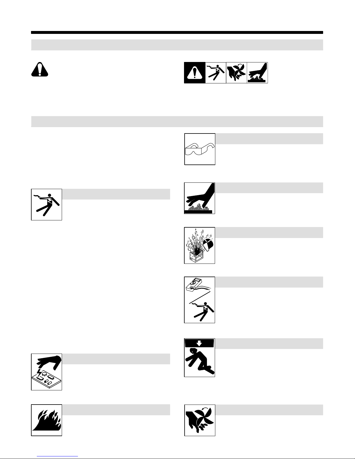
SECTION 1 – SAFETY PRECAUTIONS FOR SERVICING
1-1. Symbol Usage
OM-180 670M - 1/00, safety_stm 5/97
Means Warning! Watch Out! There are possible hazards
with this procedure! The possible hazards are shown in
the adjoining symbols.
Y Marks a special safety message.
. Means “Note”; not safety related.
1-2. Servicing Hazards
Y The symbols shown below are used throughout this manual to
call attention to and identify possible hazards. When you see
the symbol, watch out, and follow the related instructions to
avoid the hazard.
Y Only qualified persons should service, test, maintain, and re-
pair this unit.
Y During servicing, keep everybody, especially children, away.
ELECTRIC SHOCK can kill.
D Do not touch live electrical parts.
D Turn Off welding power source an d wi re f ee de r
and disconnect and lockout input power using
line disconnect switch, circuit breakers, or by removing plug from receptacle, o r stop engine before servicing unless the procedure specifically requires an energized unit.
D Insulate yourself from ground by standing or working on dry insulat-
ing mats big enough to prevent contact with the ground.
D Do not leave live unit unattended.
D If this procedure requires an energized unit, have only personnel
familiar with and following standard safety practices do the job.
D When testing a live unit, use the one-hand method. Do not put both
hands inside unit. Keep one hand free.
D Disconnect input power conductors from deenergized supply line
BEFORE moving a welding power source.
SIGNIFICANT DC VOLTAGE exists after removal of
input power on inverters.
D Turn Off inverter, disconnect input power, and discharge input
capacitors according to instructions in Maintenance Section before
touching any parts.
This group of symbols means Warning! Watch Out! possible
ELECTRIC SHOCK, MOVING PARTS, and HOT PARTS hazards.
Consult symbols and related instructions below for necessary actions
to avoid the hazards.
FLYING METAL can injure eyes.
D Wear safety glasses with side shields or face
shield during servicing.
D Be careful not to short metal tools, parts, or
wires together during testing and servicing.
HOT PARTS can cause severe burns.
D Do not touch hot parts bare handed.
D Allow cooling period before working on welding
gun or torch.
EXPLODING PARTS can cause injury.
D Failed parts can explode or cause other parts to
explode when power is applied to inverters.
D Always wear a face shield and long sleeves
when servicing inverters.
SHOCK HAZARD from testing.
D Turn Off welding power source an d wi re f ee de r
or stop engine before making or changing meter lead connections.
D Use at least one meter lead that has a self-
retaining spring clip such as an alligator clip.
D Read instructions for test equipment.
FALLING UNIT can cause injury.
STATIC (ESD) can damage PC boards.
D Put on grounded wrist strap BEFORE handling
boards or parts.
D Use proper static-proof bags and boxes to
store, move, or ship PC boards.
FIRE OR EXPLOSION hazard.
D Do not place unit on, over, or near combustible
surfaces.
D Do not service unit near flammables.
D Use lifting eye to lift unit only, NOT running
gear, gas cylinders, or any other accessories.
D Use equipment of adequate capacity to lift and
support unit.
D If using lift forks to move unit, be sure forks are
long enough to extend beyond opposite side of
unit.
MOVING PARTS can cause injury.
D Keep away from moving parts such as fans.
D Keep all doors, panels, covers, and guards
closed and securely in place.
TM-180 670 Page 1XMT 304
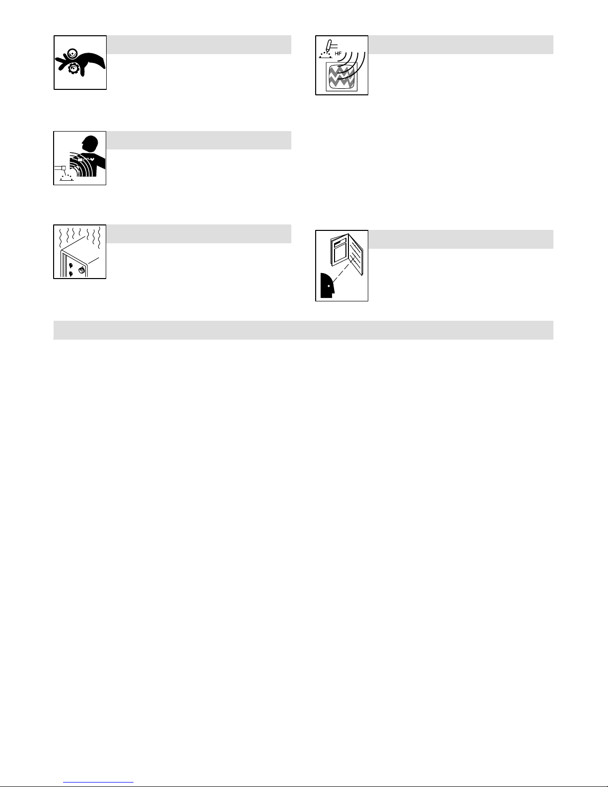
MOVING PARTS can cause injury.
H.F. RADIATION can cause interference.
D Keep away from moving parts.
D Keep away from pinch points such as drive
rolls.
MAGNETIC FIELDS can affect pacemakers.
D Pacemaker wearers keep away from servicing
areas until consulting your doctor.
OVERUSE can cause OVERHEATING.
D Allow cooling period; follow rated duty cycle.
D Reduce current or reduce duty cycle before
starting to weld again.
D Do not block or filter airflow to unit.
1-3. EMF Information
D High-frequency (H.F.) can interfere with radio
navigation, safety services, computers, and
communications equipment.
D Have only qualified persons familiar with
electronic equipment install, test, and service
H.F. producing units.
D The user is responsible for having a qualified electrician prompt-
ly correct any interference problem resulting from the installation.
D If notified by the FCC about interference, stop using the
equipment at once.
D Have the installation regularly checked and maintained.
D Keep high-frequency source doors and panels tightly shut, keep
spark gaps at correct setting, and use grounding and shielding to
minimize the possibility of interference.
READ INSTRUCTIONS.
D Use MILLER Testing Booklet (Part No. 150
853) when servicing this unit.
D Consult the Owner’s Manual for welding safety
precautions.
D Use only genuine MILLER replacement parts.
Considerations About Welding And The Effects Of Low Frequency
Electric And Ma g netic Fields
Welding current, as it flows through welding cables, will cause electromagnetic fields. There has been and still is some concern about such
fields. However, after examining more than 500 studies spanning 17
years of research, a special blue ribbon committee of the National
Research Council concluded that: “The body of evidence, in the
committee’s judgment, has not demonstrated that exposure to power-
frequency electric and magnetic fields is a human-health hazard.”
However, studies are still going forth and evidence continues to be
examined. Until the final conclusions of the research are reached, you
may wish to minimize your exposure to electromagnetic fields when
welding or cutting.
To reduce magnetic fields in the workplace, use the following
procedures:
1. Keep cables close together by twisting or taping them.
2. Arrange cables to one side and away from the operator.
3. Do not coil or drape cables around your body.
4. Keep welding power source and cables as far away from operator as practical.
5. Connect work clamp to workpiece as close to the weld as possible.
About Pacemakers:
Pacemaker wearers consult your doctor first. If cleared by your doctor,
then following the above procedures is recommended.
TM-180 670 Page 2 XMT 304
SECTION 2 – DEFINITIONS
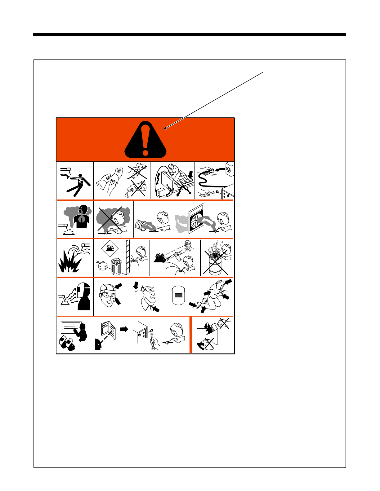
2-1. Manufacturer’s Warning Label Definitions
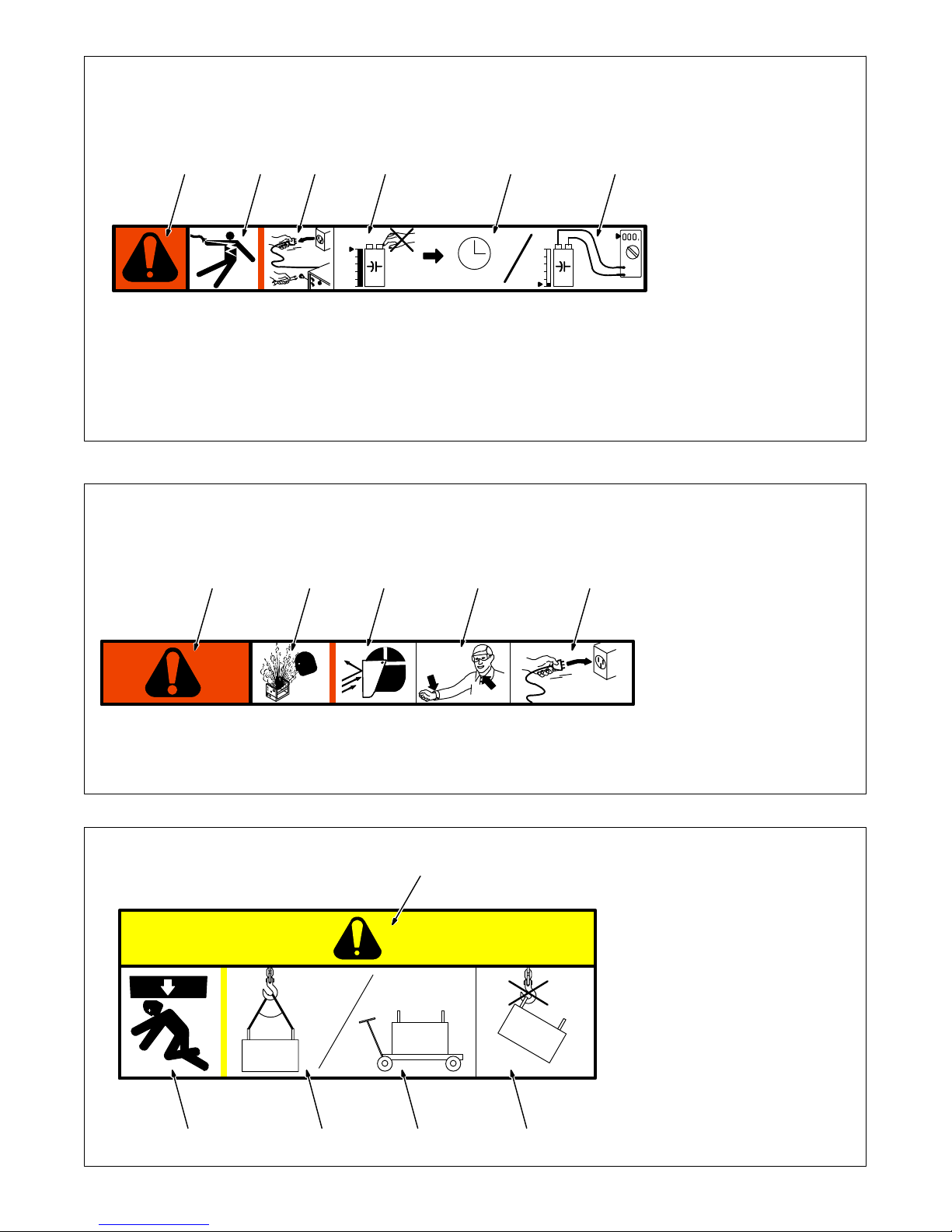
1 1.1 1.2 1.3
2 2.1
3 3.1 3.2 3.3
4 4.1
56
+
2.2
+
2.3
+
+
S-179 310
Warning! Watch Out! There are
possible hazards as shown by the
symbols.
1 Electric shock from welding
electrode or wiring can kill.
1.1 Wear dry insulating gloves.
Do not touch electrode with
bare hand. Do not wear wet or
damaged gloves.
1.2 Protect yourself from electric
shock by insulating yourself
from work and ground.
1.3 Disconnect input plug or
power before working on
machine.
2 Breathing welding fumes can
be hazardous to your health.
2.1 Keep your head out of the
fumes.
2.2 Use forced ventilation or local
exhaust to remove the fumes.
2.3 Use ventilating fan to remove
fumes.
3 Welding sparks can cause
explosion or fire.
3.1 Keep flammables away from
welding. Do not weld near
flammables.
3.2 Welding sparks can cause
fires. Have a fire extinguisher
nearby, and have a
watchperson ready to use it.
3.3 Do not weld on drums or any
closed containers.
4 Arc rays can burn eyes and
injure skin.
4.1 Wear hat and safety glasses.
Use ear protection and button
shirt collar. Use welding
helmet with correct shade of
filter. Wear complete body
protection.
5 Become trained and read the
instructions before working on
the machine or welding.
6 Do not remove or paint over
(cover) the label.
1/96
TM-180 670 Page 3XMT 304
1 Warning! Watch Out! There
2 Electric shock from wiring can
3 Disconnect input plug or
1234 5 6
4 Hazardous voltage remains
V
V
> 60 s
V
S-179 190-A
5 Always wait 60 seconds after
6 Check input capacitor voltage,
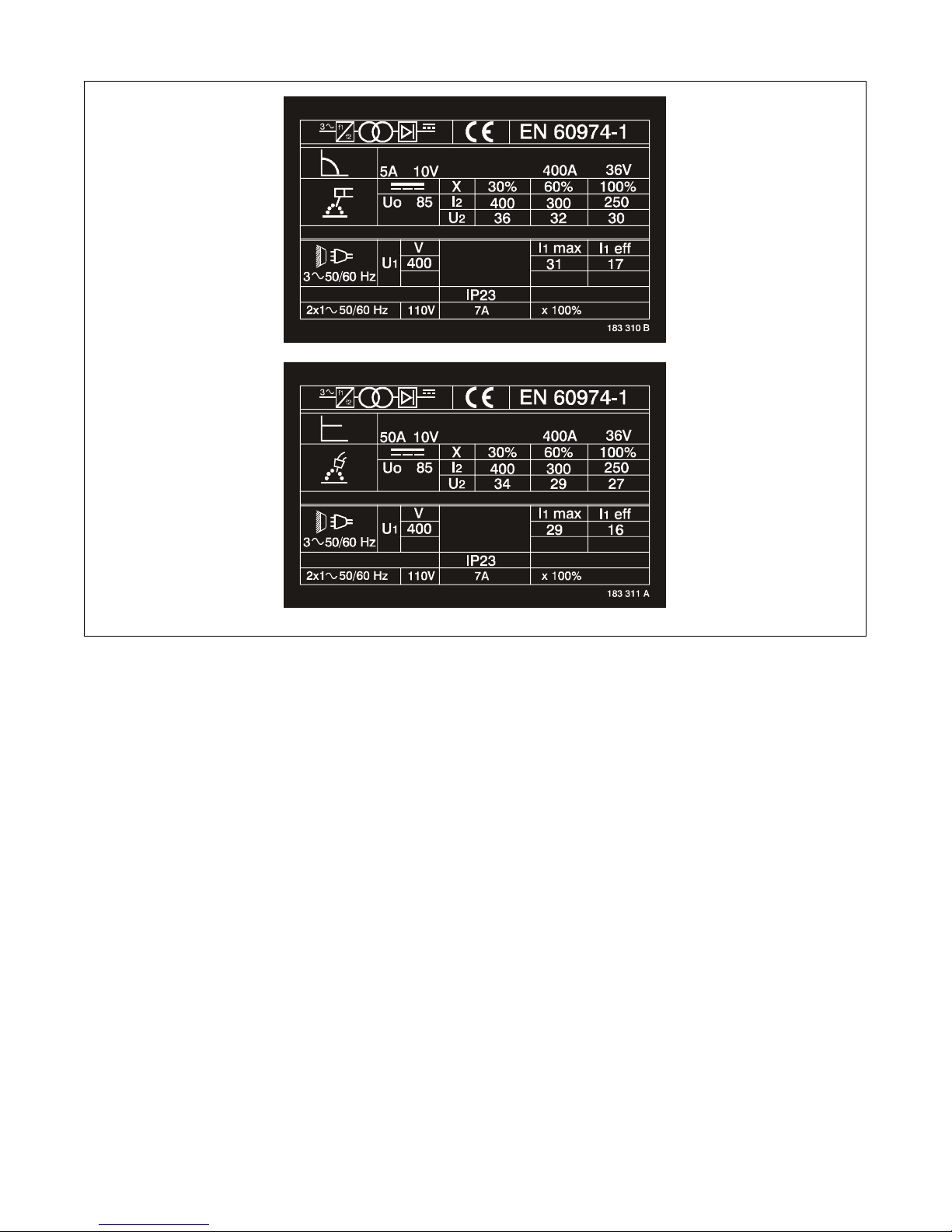
1 Warning! Watch Out! There
2 When power is applied failed
1 23 4 5
3 Flying pieces of parts can
4 Always wear long sleeves and
S-179 304-A
5 After taking proper
are possible hazards as
shown by the symbols.
kill.
power before working on
machine.
on input capacitors after
power is turned off. Do not
touch fully charged
capacitors.
power is turned off before
working on unit, OR
and be sure it is near 0 before
touching any parts.
4/96
are possible hazards as
shown by the symbols.
parts can explode or cause
other parts to explode.
cause injury. Always wear a
face shield when servicing
unit.
button your collar when
servicing unit.
precautions as shown,
connect power to unit.
∠= <60
∠
2345
TM-180 670 Page 4 XMT 304
4/96
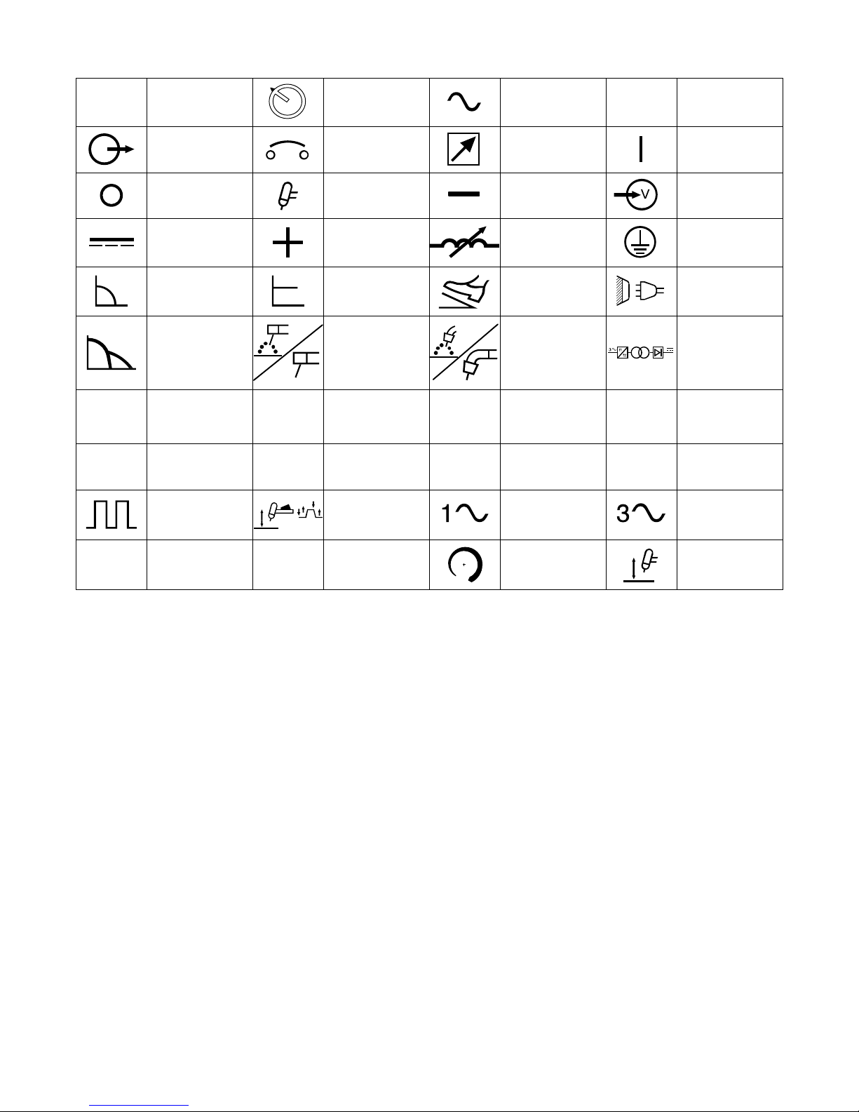
1 Warning! Watch Out! There
1
are possible hazards as
shown by the symbols.
2 Falling equipment can cause
injury and damage to unit.
3 Always lift and support unit
using both handles. Keep
angle of lifting device less
than 60 degrees.
°
4 Use a proper cart to move
unit.
5 Do not use one handle to lift
or support unit.
S-179 309-A
1/96
2-2. Manufacturer’s Rating Labels
TM-180 670 Page 5XMT 304
2-3. Symbols And Definitions
A
U
0
Hz
Amperage Panel
Output Circuit Breaker Remote On
Off
Direct Current
(DC)
Constant Current Constant Voltage Foot Control Line Connection
Arc Force
Rated No Load
Voltage (A verage) U
Hertz
Pulsed
IP
Gas Tungsten Arc
Shielded Metal Arc
Welding (SMAW)
Primary Voltage
1
Lift-Arc Trigger
Hold Operation
Welding
Positive Inductance
U
2
Degree Of
Protection
(GTAW)
I
2
Alternating
Current (AC)
Negative Voltage Input
Gas Metal Arc
Welding (GMAW)
Conventional
Load Voltage
Rated Welding
Current
Single Phase Three Phase
V
X
%
Voltage
Protective Earth
(Ground)
Three Phase Static
Frequency Con-
verter-
Transformer-
Rectifier
Duty Cycle
Percent
I
1max
Rated Maximum
Supply Current
I
1eff
Maximum Effective
Supply Current
Increase
Lift-Arc Operation
(GTAW)
TM-180 670 Page 6 XMT 304
3-1. Specifications
SECTION 3 – INSTALLATION
Rated Welding
Output Range Range
Output
300 A @
32 Volts DC,
60% Duty Cycle
*While idling
Voltage
Range
10 – 35 5 – 400 90 23
Amperage
Range
3-2. Duty Cycle And Overheating
Maximum
Open-Circuit
Voltage DC
IP Rating
Amperes Input
at Rated Load
Output 50/60 Hz
400 V KVA KW
17.0
(0.15*)
Duty Cycle is percentage of 10 mi n utes that unit can weld at rated load
without overheating.
If unit overheats, output stops, a
Help message is displayed (see
Section 8-3), and cooling fan runs.
Wait fifteen minutes for unit to cool.
Reduce amperage or duty cycle before welding.
Y Exceeding duty cycle can
12.4
(0.09*)
damage unit and void warranty.
11.5
(0.04*)
Overheating
60% Duty Cycle
6 Minutes Welding 4 Minutes Resting
0
15
Minutes
A
OR
Reduce Duty Cycle
Ref. SA-178 651
TM-180 670 Page 7XMT 304
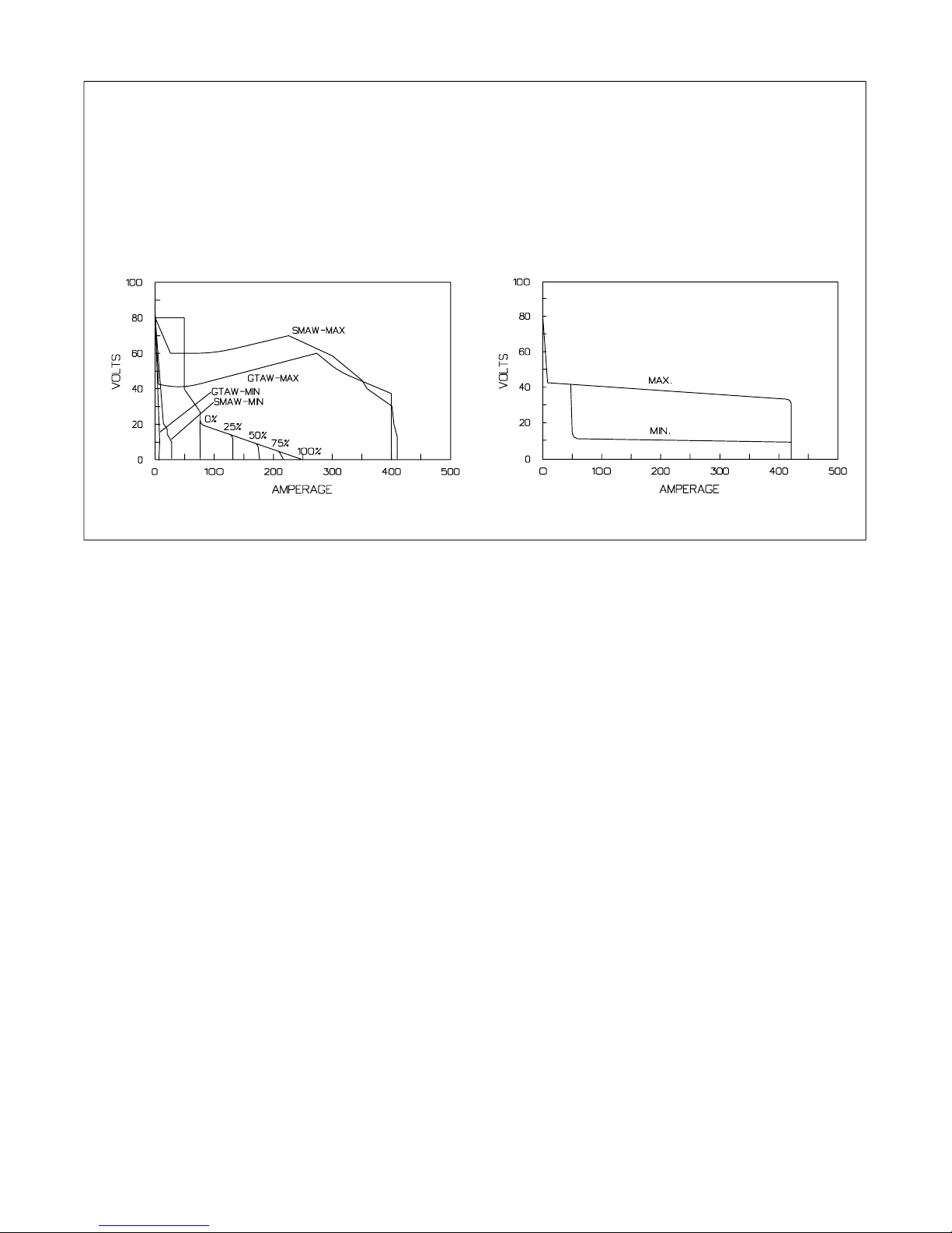
3-3. Volt-Ampere Curves
Volt-ampere curves show minimum
and maximum voltage and amperage output capabilities of unit.
Curves of other settings fall between curves shown.
A. CC Mode
ARC CONTROL
B. CV Mode
va_curve1 4/95 – SA-178 652 / SA-178 653
TM-180 670 Page 8 XMT 304
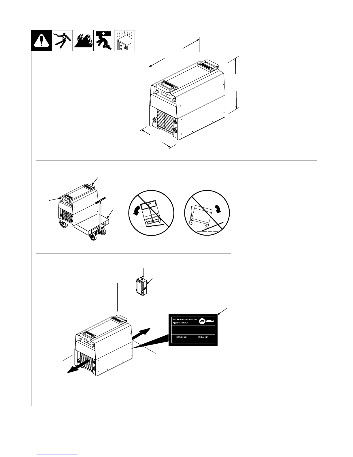
3-4. Selecting A Location
Dimensions And Weight
87 lb (39.5 kg)
24 in
(610 mm)
17 in
(432 mm)
12-1/2 in
(318 mm)
Movement
1
Location
1
2
Y Do not move or operate unit
where it could tip.
4
3
18 in
(460 mm)
1 Lifting Handles
Use handles to lift unit.
2 Hand Cart
Use cart or similar device to move
unit.
3 Plate Label
Use label to determine input power
needs.
4 Line Disconnect Device
Locate unit near correct input
power supply.
Y Special installation may be
required where gasoline or
volatile liquids are present –
see NEC Article 511 or CEC
Section 2 0 .
18 in
(460 mm)
loc_2 3/96 - ST-801 192
TM-180 670 Page 9XMT 304
3-5. Weld Output Terminals And Selecting Cable Sizes
Y ARC WELDING can cause Electromagnetic Interference.
To reduce possible interference, keep weld cables as short as possible, close together, and down low, such as on the floor.
Locate welding operation 100 meters from any sensitive electronic equipment. Be sure this welding machine is installed
and grounded according to this manual. If interference still occurs, the user must take extra measures such as moving
the welding machine, using shielded cables, using line filters, or shielding the work area.
Total Cable (Copper) Length In Weld Circuit Not Exceeding*
Weld Output
Terminals
+
Output Receptacles
–
100 ft (30 m)**
Or Less
Welding
Amperes
100 4 (20)** 4 (20) 4 (20) 3 (30) 2 (35) 1 (50) 1/0 (60) 1/0 (60)
150 3 (30)** 3 (30) 2 (35) 1 (50) 1/0 (60) 2/0 (70) 3/0 (95) 3/0 (95)
200 3 (30) 2 (35) 1 (50) 1/0 (60) 2/0 (70) 3/0 (95) 4/0 (120) 4/0 (120)
250 2 (35) 1 (50) 1/0 (60) 2/0 (70) 3/0 (95) 4/0 (120)
300 1 (50) 1/0 (60) 2/0 (70) 3/0 (95) 4/0 (120)
350 1/0 (60) 2/0 (70) 3/0 (95) 4/0 (120)
400 1/0 (60) 2/0 (70) 3/0 (95) 4/0 (120)
500 2/0 (70) 3/0 (95) 4/0 (120)
600 3/0 (95) 4/0 (120)
10 – 60%
Duty
Cycle
60 – 100%
Duty
Cycle
150 ft
(45 m)
2-2/0
(2x70)
200 ft
(60 m)
250 ft
(70 m)
10 – 100% Duty Cycle
2-2/0
(2x70)
2-2/0
(2x70)
2-2/0
(2x70)
2-3/0
(2x95)
2-3/0
(2x95)
2-4/0
(2x120)
300 ft
(90 m)
2-2/0
(2x70)
2-3/0
(2x95)
2-3/0
(2x95)
2-4/0
(2x120)
3-3/0
(3x95)
350 ft
(105 m)
2-2/0
(2x70)
2-3/0
(2x95)
2-3/0
(2x95)
2-4/0
(2x120)
3-3/0
(3x95)
3-4/0
(3x120)
400 ft
(120 m)
2-2/0
(2x70)
2-3/0
(2x95)
2-4/0
(2x120)
2-4/0
(2x120)
3-3/0
(3x95)
3-4/0
(3x120)
*Weld cable size (AWG) is based on either a 4 volts or less drop or a current density of at least 300 circular mils per ampere.
**( ) = mm2 for metric use. S-0007-E
TM-180 670 Page 10 XMT 304
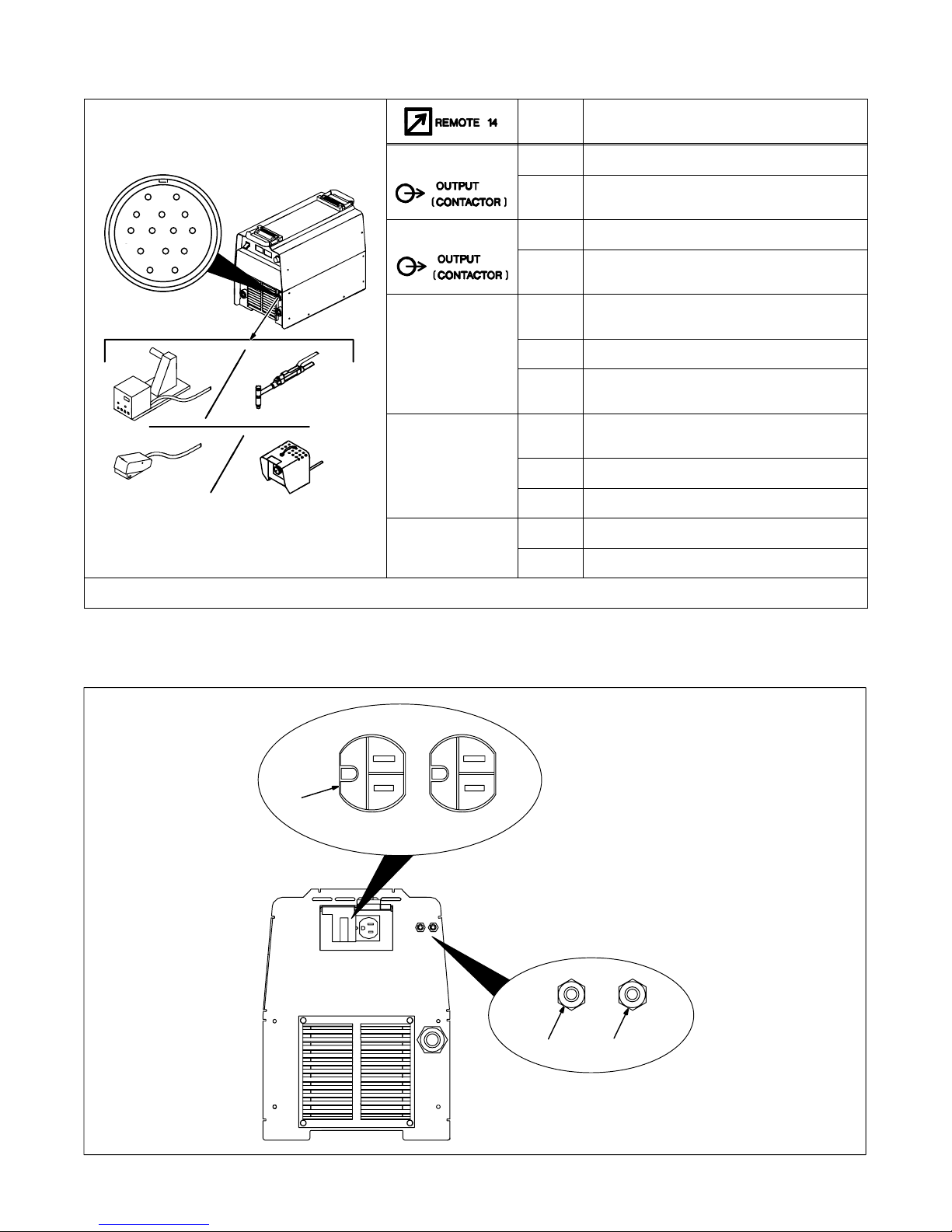
3-6. Remote 14 Receptacle Information
C
VOLTAGE
Socket* Socket Information
AJ
K
I
B
L
C
D
*The remaining sockets are not used.
I
NH
M
G
F
E
ST-801 192
24 VOLTS AC
24 VOLTS AC
115 VOLTS AC
115 VOLTS AC
REMOTE
OUTPUT
CONTROL
A/V
A/V
AMPERAGE
VOLTAGE
GND
A 24 volts ac. Protected by circuit breaker CB2.
B Contact closure to A completes 24 volts ac con-
tactor control circuit.
I 115 volts ac. Protected by circuit breaker CB1.
J Contact closure to I completes 115 volts ac con-
tactor control circuit.
C Output to remote control; 0 to +10 volts dc, +10
volts dc in MIG mode.
D Remote control circuit common.
E 0 to +10 volts dc input command signal from re-
mote control.
H V oltage feedback; +1 volt dc per 10 output recep-
tacle volts.
F Current feedback; +1 volt dc per 100 amperes.
M CC/CV select
G Circuit common for 24 a nd 115 volts ac circuits.
K Chassis common.
3-7. 110 Volt AC Duplex Receptacle
1
1 110 V 7 A AC Receptacle
Power is shared between duplex
receptacle and Remote 14 receptacle (see Section 3-6).
2 Circuit Breaker CB1
3 Circuit Breaker CB2
CB1 protects 110 volt ac portion of
duplex receptacle and Remote 14
receptacle from overload.
CB2 protects 24 volt ac portion of
Remote 14 receptacle from
overload.
Press button to reset breaker.
2 3
Ref. ST-801 245-A
TM-180 670 Page 11XMT 304
3-8. Electrical Service Guide
NOTE
Input Voltage
Input Amperes At Rated Output
Max Recommended Standard Fuse Or Circuit Breaker Rating In Amperes
Reference: 1996 National Electrical Code (NEC). S-0092J
Actual input voltage should not exceed ± 10% of indicated required input voltage. If
actual input voltage is outside of this range, output may not be available.
400 (Three Phase Only)
17.0
30
“
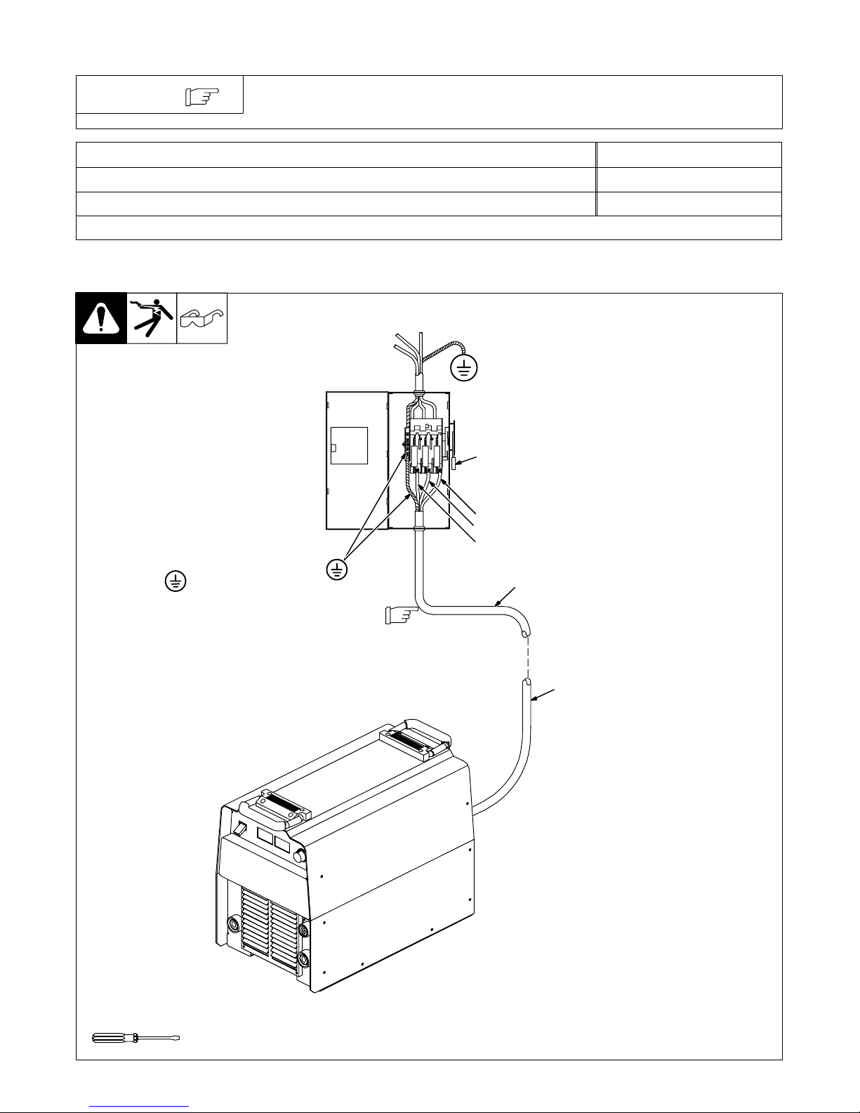
3-9. Connecting Input Power
Y Disconnect and lockout/tag-
out input power before connecting input conductors
from unit.
Y Have only qualified persons
make this installtion.
Check input voltage available at
site.
1 Line Disconnect Device
2 Input And Grounding
Conductors
Select type and size of overcurrent
protection using Section 3-8.
Y Always connect green/yel-
low wire to supply grounding terminal, never to a line
terminal.
Y Always connect grounding
conductor first.
1
L1
L2
L3
= GND/PE
Green/Yellow
Install conductors into a deenergized
line dissconnect device.
2
2
Tools Needed:
TM-180 670 Page 12 XMT 304
Input_9_99 / Ref. ST-144 221 / ST-801 192
SECTION 4 – OPERATION
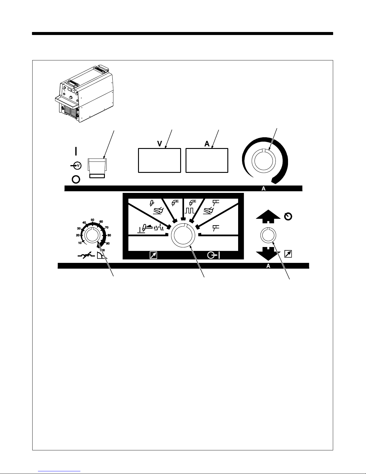
4-1. Front Panel Controls
1
7
2
3
5
4
6
ST-179 275
1 Power On/Off Switch
. The fan motor is thermostatically
controlled and only runs when cooling is
needed.
2 Voltmeter (see Section 4-2)
3 Ammeter (see Section 4-2)
4 Voltage/Amperage Adjustment Control
5 Mode Switch
The Mode switch setting determines both the
process and output On/Off control (see Section 4-3. Source of control (panel or remote)
for the amount of output is selected on the
Voltage/Amperage Control switch.
For Air Carbon Arc (CAC-A) cutting and
gouging, place switch in Stick position. For
best results, place Inductance/Dig control in
the maximum position.
6 Voltage/Amperage Control Switch
For front panel control, place switch in Panel
position.
For remote control, make connections to Re-
mote 14 receptacle, and place switch in
Remote position. In most modes, remote
control is a percent o f the Voltage/Amperage
Adjustment control setting (the value selected on Voltage/Amperage Adjustment
control is maximum available on remote). In
the MIG mode, remote control provides full
range of unit output regardless of V/A Adjust
control setting.
7 Inductance/Dig Control
Control adjusts Dig when a Stick (SMAW)
welding position is selected on mode switch.
When set lower, short-circuit amperage at
low arc voltage is the same as normal welding
amperage.
When set higher, short-circuit amperage is increased at low arc voltage to assist with arc
starts as well as reduce sticking while welding (see volt-ampere curves in Section 3-3).
Select setting best suited for application.
Control adjusts inductance when a MIG
(GMAW) position is selected on the mode
switch. Inductance determines the “wetness”
of the weld puddle. When set higher, “wet-
ness” (puddle fluidity) increases.
When pulsed MIG, or one of the TIG (GTAW)
processes is selected, this control is not functional.
TM-180 670 Page 13XMT 304
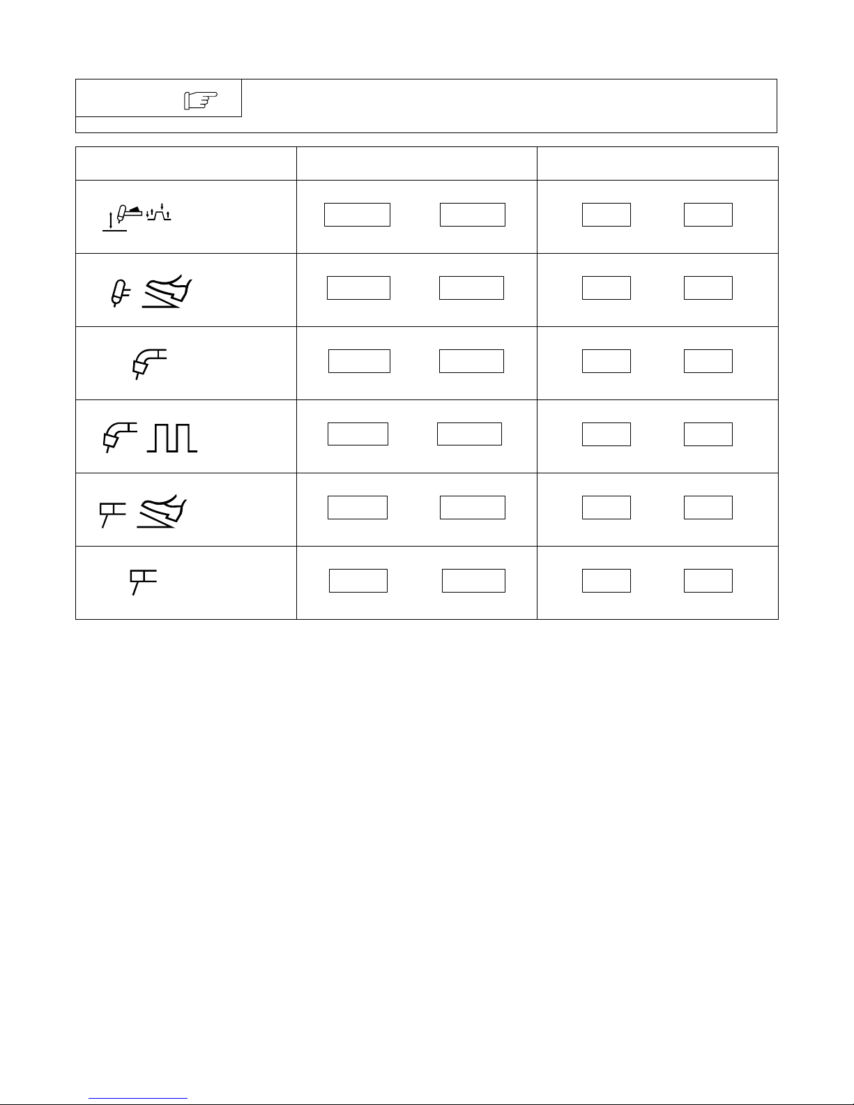
4-2. Meter Functions
NOTE
The meters display the actual weld output values for approximately three seconds
after the arc is broken.
Mode Meter Reading At Idle Meter Reading While Welding
VA
10.3 85
Actual Volts Actual Amps
VA
10.3 85
Actual Volts Actual Amps
VA
24.5 250
Actual Volts Actual Amps
VA
24.5 250
Actual Volts Actual Amps
VA
24.5 85
Actual Volts Actual Amps
Lift-Arc T rigger
Hold TIG (GTA W)
TIG (GTAW)
MIG (GMAW)
Pulsed MIG
(GMAW-P)
Remote
Control SMAW
VA
85
Blank Preset Amps
VA
85
Blank Preset Amps
VA
24.5
Preset Volts Blank
VA
PPP PPP
Pulse Display Pulse Display
VA
85
Blank Preset Amps
Panel Control
SMAW
VA
85.0 85
Actual Volts (OCV) Preset Amps
VA
24.5 85
Actual Volts Actual Amps
TM-180 670 Page 14 XMT 304
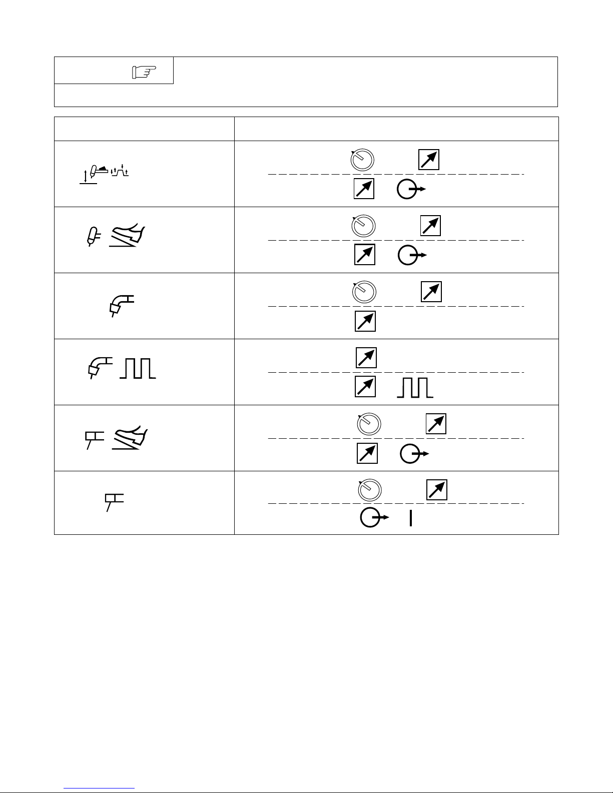
4-3. Mode Switch Settings
NOTE
The SMAW modes provide the Adaptive Hot Start feature, which automatically
increases the output amperage at the start of a weld should the start require it. This
eliminates electrode sticking at arc start.
Mode Output Control
Lift-Arc T rigger
Hold TIG (GTA W)
TIG (GTA W) With
HF Unit,
Pulsing Device,
Or Remote Control
MIG (GMAW)
Pulsed MIG
(GMAW-P)
(Requires an
external
pulsing device.)
Select: or Amp
Requires: Control
Select: or Amp
Requires: Control
Select: or Volt
Requires: Feeder
Select: Volt
Requires: Feeder or Control
Remote
Control SMAW
Panel Control
SMAW
Select: or Amp
Requires: Control
Select: or Amp
Weld
TM-180 670 Page 15XMT 304
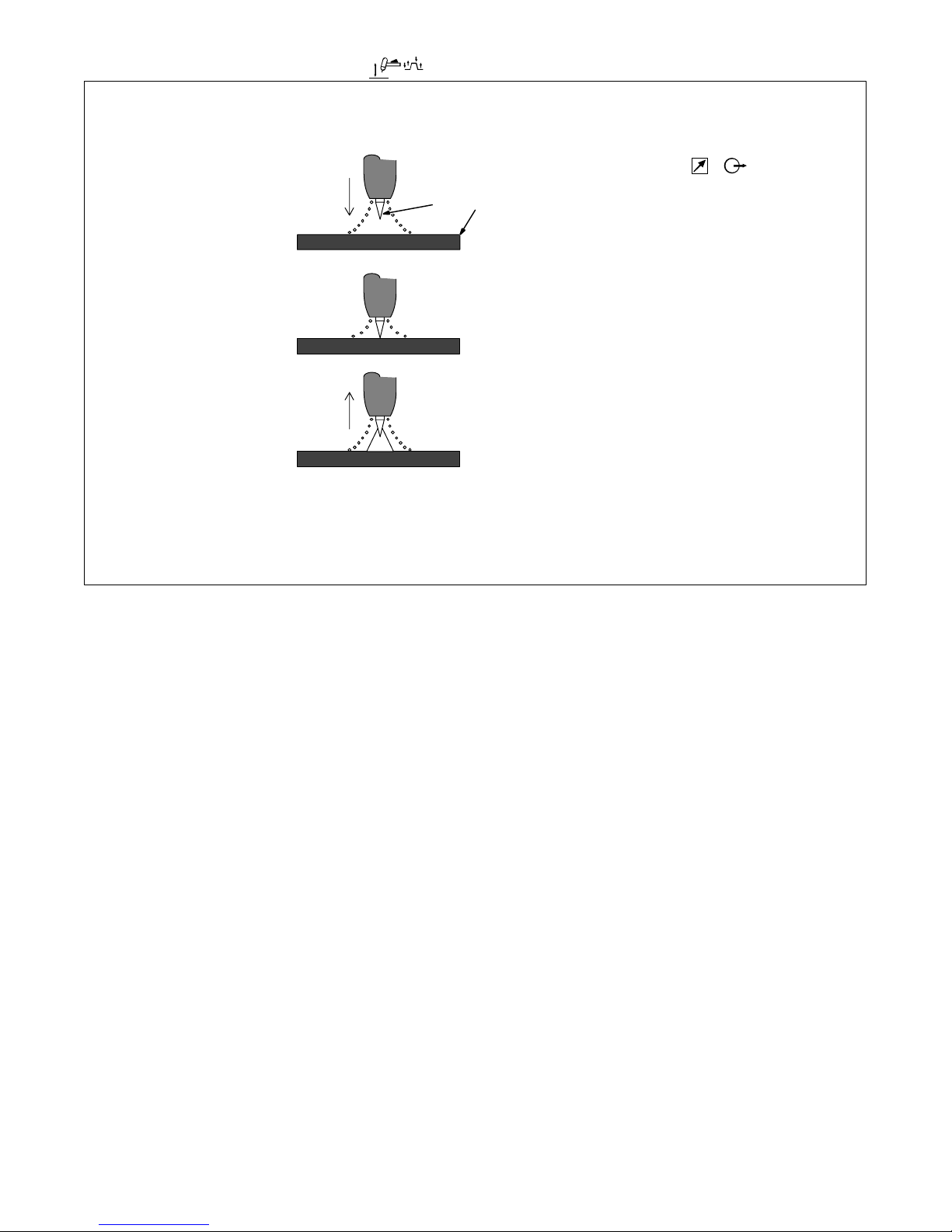
4-4. Lift-Arc Trigger Hold TIG
“Touch”
Do NOT Strike Like A Match!
1
1 – 2
Seconds
1 TIG Electrode
2 Workpiece
. Procedure requires:
control
2
Start sequence:
• Touch tungsten electrode to
workpiece at weld start point.
• Momentarily depress output
switch.
• Slowly lift electrode. An arc will
form when electrode is lifted.
• To stop welding, momentarily
depress output switch and output will shut off.
Note: If output switch is momentarily depressed and tungsten is
not touching workpiece:
Do not touch tungsten to work.
Output will shut off in 3 seconds.
Start sequence over.
Ref. S-156 279
TM-180 670 Page 16 XMT 304

Notes
TM-180 670 Page 17XMT 304

SECTION 5 – THEORY OF OPERATION
1 Power On/Off Switch S1
Provides on/off control of welding
power source.
2 Filter Board PC6
Filters line input power.
3 Input Rectifier SR1
Changes the ac line input power to
full-wave rectified dc.
4 Control Transformer T2
Supplies power to control board
PC1, interconnecting board PC2,
and Remote 14 receptacle RC1.
5 Circuit Breaker CB1
Provides overload protection for
115 volts ac portion of Remote 14
receptacle RC1 and optional 115
volt ac receptacle.
6 Circuit Breaker CB2
Provides overload protection for 24
volts ac portion of Remote 14
receptacle RC1.
7 115 Volt AC Receptacle
Connects auxiliary equipment to
welding power source (optional fo r
CC models).
8 Remote 14 Receptacle RC1
Connects remote amperage or
voltage and contactor controls.
9 Control Board PC1
Controls weld output by changing
gate pulses (frequency of pulses) to
IGBT power modules PM1 and
PM2 after comparing current or
voltage feedback to reference level
set by R2 on PC3.
10 400 V Input Contactor W1
Connects the 190 volts ac secon-
dary voltage from T2 to interconnecting b o ard PC2 to balance voltage on input capacitors C3 and C4.
Effective w/KK104771, this circuit
has been removed.
11 Fan Motor FM
Provides cooling of internal compo-
nents.
12 Display Board PC3
Consists of voltmeter V, ammeter
A, Inductance/Dig control R44,
Voltage/Amperage Adjustment
control R2, Mode switch S3, and
Voltage/Amperage Control switch
S2.
13 Voltmeter V, Ammeter A
See Section 4-2.
14 Inductance/Dig Control R44
(CC/CV Models) Or Dig
Control R44 (CC Models)
In CV mode, R44 functions as an inductance control modifying the response of the arc. In CC mode, R44
functions as a dig control.
Three-Phase
Line Input
Power
8
Remote 14
Receptacle
RC1
1
Power On/
Off Switch
2
Filter Board
PC6
7
115 Volts AC
Receptacle
S1
4
115
VAC24VAC
5
Circuit
Breaker
CB1
6
Circuit
Breaker
CB2
3
SCR/
Integrated
Rectifier SR1
Control
Transformer T2
VAC
CenterTapped
9
12
13
Voltmeter
V
14
Inductance/
Dig Control
R44
16
Mode Switch
S3
18
Input
Capacitors
C3, C4
21
190
10
VAC
Input
Contactor
W1
18
190
VAC
Ribbon
Cable
Display Board PC3
13
Ammeter
15
Amperage
Adjustment
Control R2
17
Amperage
Switch S2
19
Inductor L1,
Choke T3
Interconnecting
Board PC2
23 23
IGBT Power
Module PM1
22
IGBT Board
PC4 PC5
Gating
Signals
Control Board PC1
A
Voltage/
Voltage/
Control
20
Inductors
L3, L4
IGBT Power
Module PM2
22
IGBT Board
11
Fan Motor
FM
Gating
Signals
TM-180 670 Page 18 XMT 304
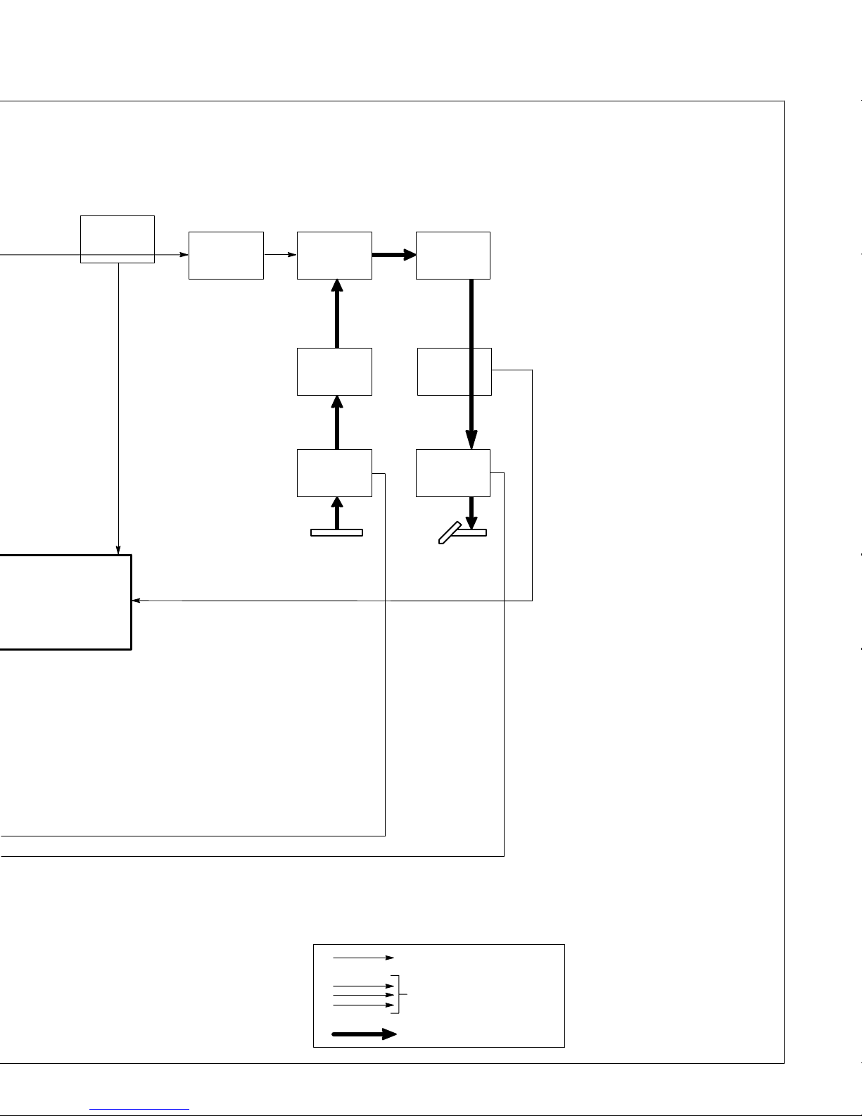
24
Current
Transformer
CT1
T1 Primary
Current
Feedback
25
Series
Resonant
Capacitor C1
Current Feedback
Voltage Feedback
Voltage Feedback
26 27
Main
Transformer
T1
28
Stabilizer
Z1
30
Negative (–)
Weld Output
Receptacle
Work
29
30
AC Or DC Control Circuits
3φ Power
Weld Current Circuit
Output
Diodes
D1, D2
Hall
Device
HD1
Positive (+)
Weld Output
Receptacle
Electrode
15 Voltage/Amperage Adjustment
Control R2 (CC/CV Models) Or
Amperage Adjustment Control
R2 (CC Models)
Selects weld output voltage or amperage level. Setting defines maximum output when remote voltage
and/or amperage control is used and
Mode switch S3 is in a CC position.
16 Mode Switch S3
Selects type of weld output, meter
function, and remote contactor or
front panel for welding process.
17 Voltage/Amperage Control
Switch S2 (CC/CV Models) Or
Amperage Control Switch S2
(CC Models)
Selects front panel or remote voltage
or amperage control.
18 Input Capacitors C3, C4
Filter the dc output voltage of SR1.
19 Inductor L1, Choke T3
Limit peak current in SR1, C3, and
C4, and filter line input power.
20 Inductors L3, L4
Limit voltage and current in IGBT’s
during turn-on and turn-off.
21 Interconnecting Board PC2
Provides electrical connections for
SR1, T1, C1, C3, C4, L1, L3, L4, T3,
and IGBT’s. Precharge and bleeder
resistors are mounted on PC2.
22 IGBT Boards PC4, PC5
Provide interconnection of gate
pulses from PC1 to PM1 and PM2.
23 IGBT Power Modules PM1,
PM2
Use very fast on/off switching action
to effectively turn the dc into ac.
24 Current Transformer CT1
Provides current feedback to PC1
from the primary of T1 for control circuit timing and to limit primary current.
25 Series Resonant Capacitor C1
Reduces losses in IGBT power mod-
ules PM1 and PM2.
26 Main Transformer T1
Energized b y on/off switching action
of PM1 and PM2, and supplies power to weld output circuit.
27 Output Diodes D1, D2
Rectify output of T1.
28 Stabilizer Z1
Smooths out welding current.
29 Hall Device HD1
Provides weld or secondary current
feedback signal to PC1.
30 Positive (+) And Negative (–)
Weld Output Receptacles
Provide weld output and allow
changing of output polarity.
TM-180 670 Page 19XMT 304
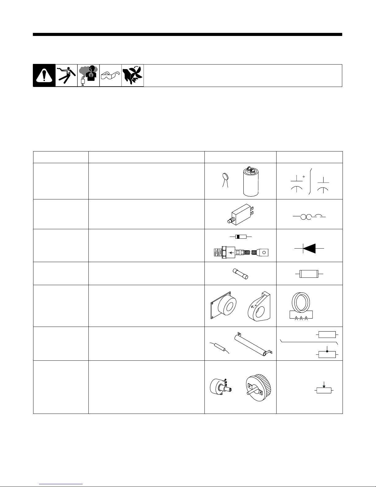
SECTION 6 – EXPLANATION OF ELECTRICAL PARTS
6-1. Safety Precautions – Read Before Using This Guide
Y WARNING: ELECTRIC SHOCK can kill.
D Disconnect input power or stop engine before servicing.
D Do not touch live electrical parts.
D Do not operate machines with covers removed.
D Have only qualified persons install, use, or service equipment.
6-2. Explanation Of Electrical Parts
P ART NAME FUNCTION PICTURE CIRCUIT SYMBOL
elect_parts 1/01
CAPACITOR A device that stores electrical energy. Large
capacitors or a “bank” of capacitors can be
used to “smooth out” the DC welding arc in a
MIG welding power source. Smaller “disk”
capacitors can be used for HF protection.
CIRCUIT BREAKER A protection device that breaks a circuit when
current levels exceed its rating. Unlike a fuse
that needs to be replaced when blown, a
circuit breaker can be reset.
DIODE A device that allows current to flow in one
direction only. Most common use is to
change AC to DC.
FUSE A protection device, usually an enclosed
piece of wire that melts and breaks the circuit
when the current exceeds the fuse rating.
HALL DEVICE Produces a small DC voltage proportional to
the current it is sensing (usually welding
current). This feedback signal can be used to
regulate the welding output (line voltage
compensation). It may even be used to drive
an ammeter.
RESISTOR A device which resists the flow of electric
current. Uses include limiting the current for a
motor brake circuit in a wire feeder and for
discharging a capacitor.
POLARIZED NON-POL.
C1 C1
CB1
D1
F1
HD1
FIXED
FIXED TAPPED
R1
R1
POTENTIOMETER
OR
RHEOSTAT
Both devices have a moveable brush that
makes contact along a resistor, allowing you
to easily change the resistance measured at
the brush (sometimes referred to as a wiper).
Their primary purpose is to give the operator
a way to adjust welding parameters such as
wire speed, preflow time, voltage,
inductance, etc.
TM-180 670 Page 20 XMT 304
VARIABLE
R1
 Loading...