

Page 1
OM-244 243B 2009−10
Processes
Multiprocess Welding
Description
Arc Welding Power Source
R
XMS 403
(400 Volts) CE
Visit our website at
www.MillerWelds.com
Page 2

From Miller to You
Thank you and congratulations on choosing Miller. Now you can get the
job done and get it done right. We know you don’t have time to do it any
other way.
That’s why when Niels Miller first started building arc welders in 1929,
he made sure his products offered long-lasting value and superior quality.
Like you, his customers couldn’t afford anything less. Miller products had
to be more than the best they could be. They had to be the best you could
buy.
Today, the people that build and sell Miller products continue the
tradition. They’re just as committed to providing equipment and service
that meets the high standards of quality and value established in 1929.
This Owner’s Manual is designed to help you get the most out of your
Miller products. Please take time to read the Safety precautions. They will
help you protect yourself against potential hazards on the worksite. We’ve
made installation and operation quick and easy. With Miller you can
count on years of reliable service with proper maintenance. And if for
some reason the unit needs repair, there’s a Troubleshooting section that
will help you figure out what the problem is. The parts list will then help
you to decide which exact part you may need to fix the problem.
Warranty and service information for your particular model are also
provided.
Working as hard as you do
− every power source from
Miller is backed by the most
hassle-free warranty in the
business.
Miller Electric manufactures a full line of
welders and welding related equipment. For
information on other quality Miller products, contact your local Miller
distributor to receive the latest full line catalog or individual catalog sheets.
Page 3

TABLE OF CONTENTS
SECTION 1 − SAFETY PRECAUTIONS - READ BEFORE USING 1. . . . . . . . . . . . . . . . . . . . . . . . . . . . . . . . . . .
1-1. Symbol Usage 1. . . . . . . . . . . . . . . . . . . . . . . . . . . . . . . . . . . . . . . . . . . . . . . . . . . . . . . . . . . . . . . . . . . . . . . .
1-2. Arc Welding Hazards 1. . . . . . . . . . . . . . . . . . . . . . . . . . . . . . . . . . . . . . . . . . . . . . . . . . . . . . . . . . . . . . . . . .
1-3. Additional Symbols For Installation, Operation, And Maintenance 3. . . . . . . . . . . . . . . . . . . . . . . . . . . . .
1-4. California Proposition 65 Warnings 4. . . . . . . . . . . . . . . . . . . . . . . . . . . . . . . . . . . . . . . . . . . . . . . . . . . . . . .
1-5. Principal Safety Standards 4. . . . . . . . . . . . . . . . . . . . . . . . . . . . . . . . . . . . . . . . . . . . . . . . . . . . . . . . . . . . .
1-6. EMF Information 4. . . . . . . . . . . . . . . . . . . . . . . . . . . . . . . . . . . . . . . . . . . . . . . . . . . . . . . . . . . . . . . . . . . . . .
SECTION 2 − DEFINITIONS 5. . . . . . . . . . . . . . . . . . . . . . . . . . . . . . . . . . . . . . . . . . . . . . . . . . . . . . . . . . . . . . . . . . .
2-1. Manufacturer’s Warning Label Definitions 5. . . . . . . . . . . . . . . . . . . . . . . . . . . . . . . . . . . . . . . . . . . . . . . . .
2-2. WEEE Label 5. . . . . . . . . . . . . . . . . . . . . . . . . . . . . . . . . . . . . . . . . . . . . . . . . . . . . . . . . . . . . . . . . . . . . . . . .
2-3. Symbols And Definitions 8. . . . . . . . . . . . . . . . . . . . . . . . . . . . . . . . . . . . . . . . . . . . . . . . . . . . . . . . . . . . . . .
SECTION 3 − INSTALLATION 9. . . . . . . . . . . . . . . . . . . . . . . . . . . . . . . . . . . . . . . . . . . . . . . . . . . . . . . . . . . . . . . . . .
3-1. Important Information Regarding CE Products (Sold Within The EU) 9. . . . . . . . . . . . . . . . . . . . . . . . . . .
3-2. Serial Number And Rating Label Location 9. . . . . . . . . . . . . . . . . . . . . . . . . . . . . . . . . . . . . . . . . . . . . . . . .
3-3. Specifications 9. . . . . . . . . . . . . . . . . . . . . . . . . . . . . . . . . . . . . . . . . . . . . . . . . . . . . . . . . . . . . . . . . . . . . . . .
3-4. Duty Cycle And Overheating 9. . . . . . . . . . . . . . . . . . . . . . . . . . . . . . . . . . . . . . . . . . . . . . . . . . . . . . . . . . . .
3-5. Volt-Ampere Curves 10. . . . . . . . . . . . . . . . . . . . . . . . . . . . . . . . . . . . . . . . . . . . . . . . . . . . . . . . . . . . . . . . . . .
3-6. Installing Turntable for Wire Feeder on Power Source (Optional) 10. . . . . . . . . . . . . . . . . . . . . . . . . . . . . .
3-7. Dimensions And Weight 11. . . . . . . . . . . . . . . . . . . . . . . . . . . . . . . . . . . . . . . . . . . . . . . . . . . . . . . . . . . . . . . .
3-8. Selecting a Location 11. . . . . . . . . . . . . . . . . . . . . . . . . . . . . . . . . . . . . . . . . . . . . . . . . . . . . . . . . . . . . . . . . . .
3-9. Weld Output Terminals And Selecting Cable Sizes 12. . . . . . . . . . . . . . . . . . . . . . . . . . . . . . . . . . . . . . . . . .
3-10. Remote 7 Receptacle Information (TIG And Stick Only) 13. . . . . . . . . . . . . . . . . . . . . . . . . . . . . . . . . . . . .
3-11. Circuit Breakers 13. . . . . . . . . . . . . . . . . . . . . . . . . . . . . . . . . . . . . . . . . . . . . . . . . . . . . . . . . . . . . . . . . . . . . .
3-12. Filling Coolant Tank 14. . . . . . . . . . . . . . . . . . . . . . . . . . . . . . . . . . . . . . . . . . . . . . . . . . . . . . . . . . . . . . . . . . .
3-13. Electrical Service Guide 14. . . . . . . . . . . . . . . . . . . . . . . . . . . . . . . . . . . . . . . . . . . . . . . . . . . . . . . . . . . . . . . .
3-14. Connecting 3-Phase Input Power 15. . . . . . . . . . . . . . . . . . . . . . . . . . . . . . . . . . . . . . . . . . . . . . . . . . . . . . . .
SECTION 4 − OPERATION 16. . . . . . . . . . . . . . . . . . . . . . . . . . . . . . . . . . . . . . . . . . . . . . . . . . . . . . . . . . . . . . . . . . . .
4-1. Front Panel Controls 16. . . . . . . . . . . . . . . . . . . . . . . . . . . . . . . . . . . . . . . . . . . . . . . . . . . . . . . . . . . . . . . . . . .
4-2. Switching On the Unit and Recalling Factory Parameters 17. . . . . . . . . . . . . . . . . . . . . . . . . . . . . . . . . . . .
4-3. Welding Power Source Setup Menu 18. . . . . . . . . . . . . . . . . . . . . . . . . . . . . . . . . . . . . . . . . . . . . . . . . . . . . .
4-4. Remote Receptacle (RCTY) 19. . . . . . . . . . . . . . . . . . . . . . . . . . . . . . . . . . . . . . . . . . . . . . . . . . . . . . . . . . . .
4-5. Welding Process Selection 19. . . . . . . . . . . . . . . . . . . . . . . . . . . . . . . . . . . . . . . . . . . . . . . . . . . . . . . . . . . . .
4-6. Wire Type Selection in Synergic MIG or Synergic Pulsed MIG Welding 20. . . . . . . . . . . . . . . . . . . . . . . . .
4-7. Wire Diameter Selection In Synergic MIG Or Synergic Pulsed MIG Welding 20. . . . . . . . . . . . . . . . . . . .
4-8. Gas Selection in Synergic MIG or Synergic Pulsed MIG Welding 21. . . . . . . . . . . . . . . . . . . . . . . . . . . . . .
4-9. Trigger Mode Selection (L-TIG and Stick Processes) 21. . . . . . . . . . . . . . . . . . . . . . . . . . . . . . . . . . . . . . . .
4-10. Welding Parameter Setup Menu (Double Pulsed-MIG/L-TIG And Stick) 22. . . . . . . . . . . . . . . . . . . . . . . .
4-11. Preparing Power Source For MIG (GMAW) Welding Process 22. . . . . . . . . . . . . . . . . . . . . . . . . . . . . . . . .
4-12. Selecting Manual MIG Welding 23. . . . . . . . . . . . . . . . . . . . . . . . . . . . . . . . . . . . . . . . . . . . . . . . . . . . . . . . . .
4-13. Selecting Synergic MIG Welding 24. . . . . . . . . . . . . . . . . . . . . . . . . . . . . . . . . . . . . . . . . . . . . . . . . . . . . . . . .
4-14. Selecting Synergic Pulsed MIG Welding 25. . . . . . . . . . . . . . . . . . . . . . . . . . . . . . . . . . . . . . . . . . . . . . . . . .
4-15. Preparing Unit For TIG Welding 26. . . . . . . . . . . . . . . . . . . . . . . . . . . . . . . . . . . . . . . . . . . . . . . . . . . . . . . . .
4-16. TIG Lift-Arc Welding 27. . . . . . . . . . . . . . . . . . . . . . . . . . . . . . . . . . . . . . . . . . . . . . . . . . . . . . . . . . . . . . . . . . .
4-17. Preparing Unit For Stick Welding 27. . . . . . . . . . . . . . . . . . . . . . . . . . . . . . . . . . . . . . . . . . . . . . . . . . . . . . . .
SECTION 5 − MAINTENANCE & TROUBLESHOOTING 28. . . . . . . . . . . . . . . . . . . . . . . . . . . . . . . . . . . . . . . . . . .
5-1. Routine Maintenance 28. . . . . . . . . . . . . . . . . . . . . . . . . . . . . . . . . . . . . . . . . . . . . . . . . . . . . . . . . . . . . . . . . .
5-2. Help Displays 29. . . . . . . . . . . . . . . . . . . . . . . . . . . . . . . . . . . . . . . . . . . . . . . . . . . . . . . . . . . . . . . . . . . . . . . .
5-3. Troubleshooting 29. . . . . . . . . . . . . . . . . . . . . . . . . . . . . . . . . . . . . . . . . . . . . . . . . . . . . . . . . . . . . . . . . . . . . .
SECTION 6 − ELECTRICAL DIAGRAM 30. . . . . . . . . . . . . . . . . . . . . . . . . . . . . . . . . . . . . . . . . . . . . . . . . . . . . . . . . .
SECTION 7 − PARTS LIST 32. . . . . . . . . . . . . . . . . . . . . . . . . . . . . . . . . . . . . . . . . . . . . . . . . . . . . . . . . . . . . . . . . . . . .
WARRANTY
Page 4
DECLARATION OF CONFORMITY
for European Community (CE marked) products.
ITW Welding Products Italy S.r.l Via Privata Iseo 6/E, 20098 San Giuliano M.se, (MI) Italy de
clares that the product(s) identified in this declaration conform to the essential requirements and
provisions of the stated Council Directive(s) and Standard(s).
Product/Apparatus Identification:
Product Stock Number
XMS 403
Council Directives:
015 029 083
• 2006/95/EC Low Voltage
• 2004/108/EC Electromagnetic Compatibility
• 2006/42/EEC Machinery Directive
Standards:
• IEC 609741 Arc Welding Equipment Welding Power Sources: edition 3.0, 200507.
• IEC 609742 Arc Welding Equipment Water cooling systems: edition 2.0, 200711.
• IEC 6097410 Arc Welding Equipment Electromagnetic Compatibility Requirements: edition 2.0, 200708
• EN 50445:2008 Product family standard to demonstrate compliance of equipment for resistance welding, arc
welding and allied processes with the basic restrictions related to human exposure to electromagnetic fields
(0Hz300Hz)
EU Signatory:
November 12, 2009
______________________________________________________________________________
Mark Lowther
EUROPEAN DIRECTOR, TECHNOLOGY & PRODUCT DEVELOPMENT
Date of Declaration
956 142 700
Page 5
SECTION 1 − SAFETY PRECAUTIONS - READ BEFORE USING
7
Protect yourself and others from injury — read and follow these precautions.
1-1. Symbol Usage
som _2009−08
DANGER! − Indicates a hazardous situation which, if
not avoided, will result in death or serious injury. The
possible hazards are shown in the adjoining symbols
or explained in the text.
Indicates a hazardous situation which, if not avoided,
could result in death or serious injury. The possible
hazards are shown in the adjoining symbols or explained in the text.
NOTICE − Indicates statements not related to personal injury.
1-2. Arc Welding Hazards
The symbols shown below are used throughout this manual
to call attention to and identify possible hazards. When you
see the symbol, watch out, and follow the related instructions
to avoid the hazard. The safety information given below is
only a summary of the more complete safety information
found in the Safety Standards listed in Section 1-5. Read and
follow all Safety Standards.
Only qualified persons should install, operate, maintain, and
repair this unit.
During operation, keep everybody, especially children, away.
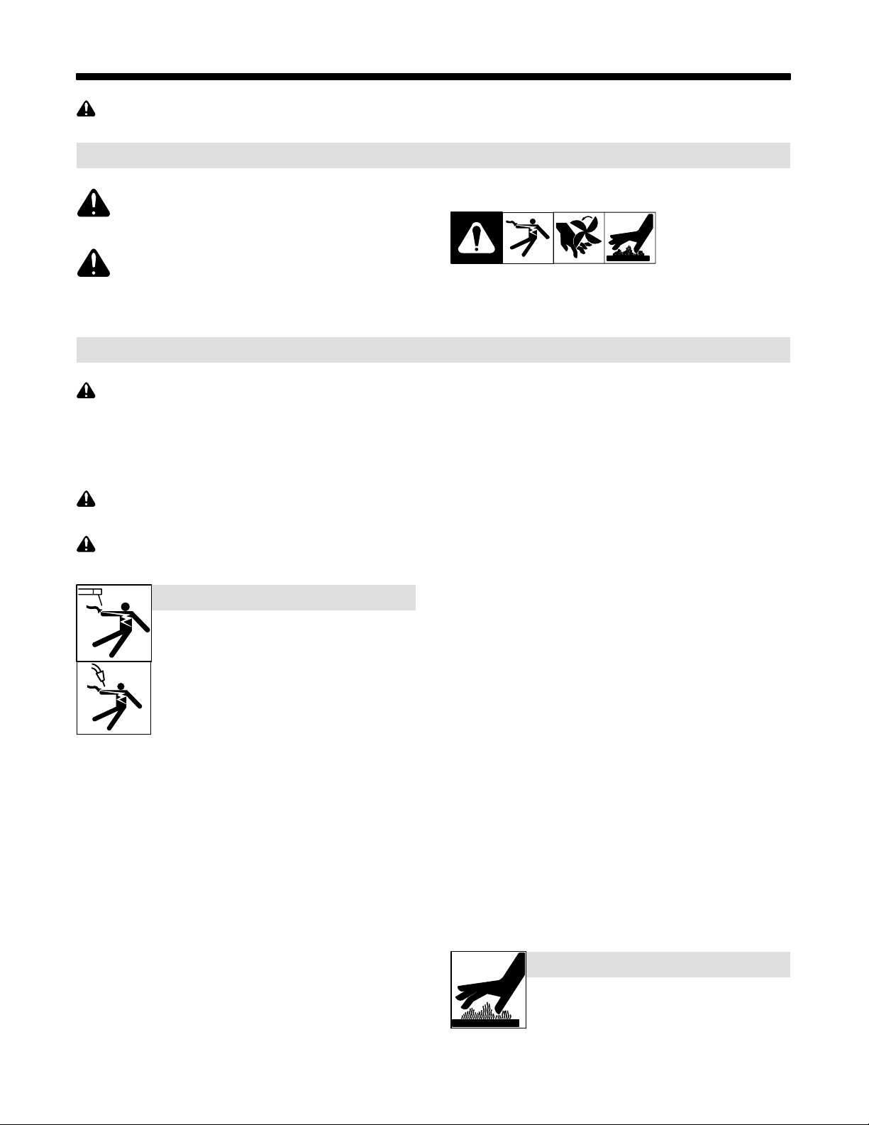
ELECTRIC SHOCK can kill.
Touching live electrical parts can cause fatal shocks
or severe burns. The electrode and work circuit is
electrically live whenever the output is on. The input
power circuit and machine internal circuits are also
live when power is on. In semiautomatic or automatic
wire welding, the wire, wire reel, drive roll housing,
and all metal parts touching the welding wire are
electrically live. Incorrectly installed or improperly
grounded equipment is a hazard.
D Do not touch live electrical parts.
D Wear dry, hole-free insulating gloves and body protection.
D Insulate yourself from work and ground using dry insulating mats
or covers big enough to prevent any physical contact with the work
or ground.
D Do not use AC output in damp areas, if movement is confined, or if
there is a danger of falling.
D Use AC output ONLY if required for the welding process.
D If AC output is required, use remote output control if present on
unit.
D Additional safety precautions are required when any of the follow-
ing electrically hazardous conditions are present: in damp
locations or while wearing wet clothing; on metal structures such
as floors, gratings, or scaffolds; when in cramped positions such
as sitting, kneeling, or lying; or when there is a high risk of unavoidable or accidental contact with the workpiece or ground. For these
conditions, use the following equipment in order presented: 1) a
semiautomatic DC constant voltage (wire) welder, 2) a DC manual
(stick) welder, or 3) an AC welder with reduced open-circuit voltage. In most situations, use of a DC, constant voltage wire welder
is recommended. And, do not work alone!
D Disconnect input power or stop engine before installing or
servicing this equipment. Lockout/tagout input power according to
OSHA 29 CFR 1910.147 (see Safety Standards).
. Indicates special instructions.
This group of symbols means Warning! Watch Out! ELECTRIC
SHOCK, MOVING PARTS, and HOT PARTS hazards. Consult symbols and related instructions below for necessary actions to avoid the
hazards.
D Properly install and ground this equipment according to its
Owner’s Manual and national, state, and local codes.
D Always verify the supply ground − check and be sure that input
power cord ground wire is properly connected to ground terminal in
disconnect box or that cord plug is connected to a properly
grounded receptacle outlet.
D When making input connections, attach proper grounding conduc-
tor first − double-check connections.
D Keep cords dry, free of oil and grease, and protected from hot metal
and sparks.
D Frequently inspect input power cord for damage or bare wiring −
replace cord immediately if damaged − bare wiring can kill.
D Turn off all equipment when not in use.
D Do not use worn, damaged, undersized, or poorly spliced cables.
D Do not drape cables over your body.
D If earth grounding of the workpiece is required, ground it directly
with a separate cable.
D Do not touch electrode if you are in contact with the work, ground,
or another electrode from a different machine.
D Do not touch electrode holders connected to two welding ma-
chines at the same time since double open-circuit voltage will be
present.
D Use only well-maintained equipment. Repair or replace damaged
parts at once. Maintain unit according to manual.
D Wear a safety harness if working above floor level.
D Keep all panels and covers securely in place.
D Clamp work cable with good metal-to-metal contact to workpiece
or worktable as near the weld as practical.
D Insulate work clamp when not connected to workpiece to prevent
contact with any metal object.
D Do not connect more than one electrode or work cable to any
single weld output terminal.
SIGNIFICANT DC VOLTAGE exists in inverter welding power sources AFTER removal of inputpower.
D Turn Off inverter, disconnect input power, and discharge input
capacitors according to instructions in Maintenance Section
before touching any parts.
HOT PARTS can burn.
D Do not touch hot parts bare handed.
D Allow cooling period before working on equip-
ment.
D To handle hot parts, use proper tools and/or
wear heavy, insulated welding gloves and
clothing to prevent burns.
OM-244 243 Page 1
Page 6
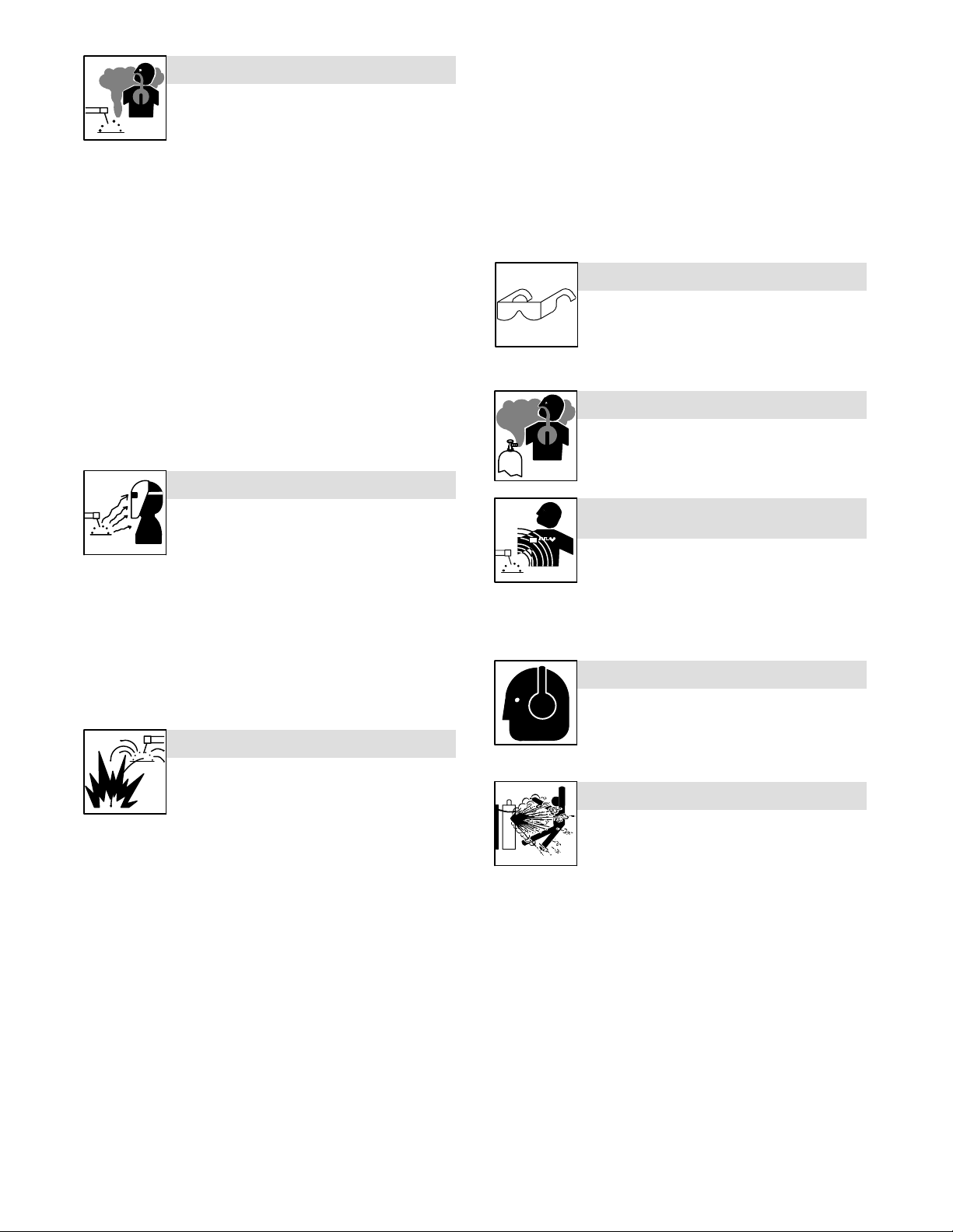
FUMES AND GASES can be hazardous.
)
Welding produces fumes and gases. Breathing
these fumes and gases can be hazardous to your
health.
D Keep your head out of the fumes. Do not breathe the fumes.
D If inside, ventilate the area and/or use local forced ventilation at the
arc to remove welding fumes and gases.
D If ventilation is poor, wear an approved air-supplied respirator.
D Read and understand the Material Safety Data Sheets (MSDSs)
and the manufacturer’s instructions for metals, consumables,
coatings, cleaners, and degreasers.
D Work in a confined space only if it is well ventilated, or while
wearing an air-supplied respirator. Always have a trained watchperson nearby. Welding fumes and gases can displace air and
lower the oxygen level causing injury or death. Be sure the breathing air is safe.
D Do not weld in locations near degreasing, cleaning, or spraying op-
erations. The heat and rays of the arc can react with vapors to form
highly toxic and irritating gases.
D Do not weld on coated metals, such as galvanized, lead, or
cadmium plated steel, unless the coating is removed from the weld
area, the area is well ventilated, and while wearing an air-supplied
respirator. The coatings and any metals containing these elements
can give off toxic fumes if welded.
ARC RAYS can burn eyes and skin.
D Remove stick electrode from holder or cut off welding wire at
contact tip when not in use.
D Wear oil-free protective garments such as leather gloves, heavy
shirt, cuffless trousers, high shoes, and a cap.
D Remove any combustibles, such as a butane lighter or matches,
from your person before doing any welding.
D After completion of work, inspect area to ensure it is free of sparks,
glowing embers, and flames.
D Use only correct fuses or circuit breakers. Do not oversize or by-
pass them.
D Follow requirements in OSHA 1910.252 (a) (2) (iv) and NFPA 51B
for hot work and have a fire watcher and extinguisher nearby.
FLYING METAL or DIRT can injure eyes.
D Welding, chipping, wire brushing, and grinding
cause sparks and flying metal. As welds cool,
they can throw off slag.
D Wear approved safety glasses with side
shields even under your welding helmet.
BUILDUP OF GAS can injure or kill.
D Shut off shielding gas supply when not in use.
D Always ventilate confined spaces or use
approved air-supplied respirator.
Arc rays from the welding process produce intense
visible and invisible (ultraviolet and infrared) rays
that can burn eyes and skin. Sparks fly off from the
weld.
D Wear an approved welding helmet fitted with a proper shade of
filter lenses to protect your face and eyes from arc rays and
sparks when welding or watching (see ANSI Z49.1 and Z87.1
listed in Safety Standards).
D Wear approved safety glasses with side shields under your
helmet.
D Use protective screens or barriers to protect others from flash,
glare and sparks; warn others not to watch the arc.
D Wear protective clothing made from durable, flame-resistant
material (leather, heavy cotton, or wool) and foot protection.
WELDING can cause fire or explosion.
Welding on closed containers, such as tanks,
drums, or pipes, can cause them to blow up. Sparks
can fly off from the welding arc. The flying sparks, hot
burns. Accidental contact of electrode to metal objects can cause
sparks, explosion, overheating, or fire. Check and be sure the area is
safe before doing any welding.
D Remove all flammables within 35 ft (10.7 m) of the welding arc. If
this is not possible, tightly cover them with approved covers.
D Do not weld where flying sparks can strike flammable material.
D Protect yourself and others from flying sparks and hot metal.
D Be alert that welding sparks and hot materials from welding can
easily go through small cracks and openings to adjacent areas.
D Watch for fire, and keep a fire extinguisher nearby.
D Be aware that welding on a ceiling, floor, bulkhead, or partition can
cause fire on the hidden side.
D Do not weld on closed containers such as tanks, drums, or pipes,
unless they are properly prepared according to AWS F4.1 (see
Safety Standards).
D Do not weld where the atmosphere may contain flammable dust,
gas, or liquid vapors (such as gasoline).
D Connect work cable to the work as close to the welding area as
practical to prevent welding current from traveling long, possibly
unknown paths and causing electric shock, sparks, and fire
hazards.
D Do not use welder to thaw frozen pipes.
OM-244 243 Page 2
workpiece, and hot equipment can cause fires and
ELECTRIC AND MAGNETIC FIELDS (EMF
can affect ImplantedMedical Devices.
D Wearers of Pacemakers and other Implanted
Medical Devices should keep away.
D Implanted Medical Device wearers should consult their doctor
and the device manufacturer before going near arc welding, spot
welding, gouging, plasma arc cutting, or induction heating
operations.
NOISE can damage hearing.
Noise from some processes or equipment can
damage hearing.
D Wear approved ear protection if noise level is
high.
CYLINDERS can explode if damaged.
Shielding gas cylinders contain gas under high
pressure. If damaged, a cylinder can explode. Since
gas cylinders are normally part of the welding
process, be sure to treat them carefully.
D Protect compressed gas cylinders from excessive heat, mechani-
cal shocks, physical damage, slag, open flames, sparks, and arcs.
D Install cylinders in an upright position by securing to a stationary
support or cylinder rack to prevent falling or tipping.
D Keep cylinders away from any welding or other electrical circuits.
D Never drape a welding torch over a gas cylinder.
D Never allow a welding electrode to touch any cylinder.
D Never weld on a pressurized cylinder − explosion will result.
D Use only correct shielding gas cylinders, regulators, hoses, and fit-
tings designed for the specific application; maintain them and
associated parts in good condition.
D Turn face away from valve outlet when opening cylinder valve.
D Keep protective cap in place over valve except when cylinder is in
use or connected for use.
D Use the right equipment, correct procedures, and sufficient num-
ber of persons to lift and move cylinders.
D Read and follow instructions on compressed gas cylinders,
associated equipment, and Compressed Gas Association (CGA)
publication P-1 listed in Safety Standards.
Page 7
1-3. Additional Symbols For Installation, Operation, And Maintenance
FIRE OR EXPLOSION hazard.
D Do not install or place unit on, over, or near
combustible surfaces.
D Do not install unit near flammables.
D Do not overload building wiring − be sure power supply system is
properly sized, rated, and protected to handle this unit.
FALLING EQUIPMENT can injure.
D Use lifting eye to lift unit only, NOT running
gear, gas cylinders, or any other accessories.
D Use equipment of adequate capacity to lift and
support unit.
D If using lift forks to move unit, be sure forks are long enough to
extend beyond opposite side of unit.
D Keep equipment (cables and cords) away from moving vehicles
when working from an aerial location.
D Follow the guidelines in the Applications Manual for the Revised
NIOSH Lifting Equation (Publication No. 94−110) when manually lifting heavy parts or equipment.
OVERUSE can cause OVERHEATING
D Allow cooling period; follow rated duty cycle.
D Reduce current or reduce duty cycle before
starting to weld again.
D Do not block or filter airflow to unit.
FLYING SPARKS can injure.
D Wear a face shield to protect eyes and face.
D Shape tungsten electrode only on grinder with
proper guards in a safe location wearing proper
face, hand, and body protection.
D Sparks can cause fires — keep flammables away.
STATIC (ESD) can damage PC boards.
D Put on grounded wrist strap BEFORE handling
boards or parts.
D Use proper static-proof bags and boxes to
store, move, or ship PC boards.
MOVING PARTS can injure.
D Keep away from moving parts.
D Keep away from pinch points such as drive
rolls.
WELDING WIRE can injure.
D Do not press gun trigger until instructed to do
so.
D Do not point gun toward any part of the body,
other people, or any metal when threading
welding wire.
MOVING PARTS can injure.
D Keep away from moving parts such as fans.
D Keep all doors, panels, covers, and guards
closed and securely in place.
D Have only qualified persons remove doors, panels, covers, or
guards for maintenance and troubleshooting as necessary.
D Reinstall doors, panels, covers, or guards when maintenance is
finished and before reconnecting input power.
READ INSTRUCTIONS.
D Read and follow all labels and the Owner’s
Manual carefully before installing, operating, or
servicing unit. Read the safety information at
the beginning of the manual and in each
section.
D Use only genuine replacement parts from the manufacturer.
D Perform maintenance and service according to the Owner’s
Manuals, industry standards, and national, state, and local
codes.
H.F. RADIATION can cause interference.
D High-frequency (H.F.) can interfere with radio
navigation, safety services, computers, and
communications equipment.
D Have only qualified persons familiar with
electronic equipment perform this installation.
D The user is responsible for having a qualified electrician prompt-
ly correct any interference problem resulting from the installation.
D If notified by the FCC about interference, stop using the
equipment at once.
D Have the installation regularly checked and maintained.
D Keep high-frequency source doors and panels tightly shut, keep
spark gaps at correct setting, and use grounding and shielding to
minimize the possibility of interference.
ARC WELDING can cause interference.
D Electromagnetic energy can interfere with
sensitive electronic equipment such as
computers and computer-driven equipment
such as robots.
D Be sure all equipment in the welding area is
electromagnetically compatible.
D To reduce possible interference, keep weld cables as short as
possible, close together, and down low, such as on the floor.
D Locate welding operation 100 meters from any sensitive elec-
tronic equipment.
D Be sure this welding machine is installed and grounded
according to this manual.
D If interference still occurs, the user must take extra measures
such as moving the welding machine, using shielded cables,
using line filters, or shielding the work area.
OM-244 243 Page 3
Page 8

1-4. California Proposition 65 Warnings
Welding or cutting equipment produces fumes or gases
which contain chemicals known to the State of California to
cause birth defects and, in some cases, cancer. (California
Health & Safety Code Section 25249.5 et seq.)
Battery posts, terminals and related accessories contain lead
and lead compounds, chemicals known to the State of
California to cause cancer and birth defects or other
reproductive harm. Wash hands after handling.
1-5. Principal Safety Standards
Safety in Welding, Cutting, and Allied Processes, ANSI Standard Z49.1,
from Global Engineering Documents (phone: 1-877-413-5184, website:
www.global.ihs.com).
Safe Practices for the Preparation of Containers and Piping for Welding
and Cutting, American Welding Society Standard AWS F4.1, from Glob-
al Engineering Documents (phone: 1-877-413-5184, website:
www.global.ihs.com).
National Electrical Code, NFPA Standard 70, from National Fire Protection Association, Quincy, MA 02269 (phone: 1-800-344-3555, website:
www.nfpa.org and www. sparky.org).
Safe Handling of Compressed Gases in Cylinders, CGA Pamphlet P-1,
from Compressed Gas Association, 4221 Walney Road, 5th Floor,
Chantilly, VA 20151 (phone: 703-788-2700, website:www.cganet.com).
Safety in Welding, Cutting, and Allied Processes, CSA Standard
W117.2, from Canadian Standards Association, Standards Sales, 5060
Spectrum Way, Suite 100, Ontario, Canada L4W 5NS (phone:
800-463-6727, website: www.csa-international.org).
Safe Practice For Occupational And Educational Eye And Face Protection, ANSI Standard Z87.1, from American National Standards Institute,
For Gasoline Engines:
Engine exhaust contains chemicals known to the State of
California to cause cancer, birth defects, or other reproductive harm.
For Diesel Engines:
Diesel engine exhaust and some of its constituents are
known to the State of California to cause cancer, birth
defects, and other reproductive harm.
25 West 43rd Street, New York, NY 10036 (phone: 212-642-4900, website: www.ansi.org).
Standard for Fire Prevention During Welding, Cutting, and Other Hot
Work, NFPA Standard 51B, from National Fire Protection Association,
Quincy, MA 02269 (phone: 1-800-344-3555, website: www.nfpa.org.
OSHA, Occupational Safety and Health Standards for General Indus-
try, Title 29, Code of Federal Regulations (CFR), Part 1910, Subpart Q,
and Part 1926, Subpart J, from U.S. Government Printing Office, Superintendent of Documents, P.O. Box 371954, Pittsburgh, PA 15250-7954
(phone: 1-866-512-1800) (there are 10 OSHA Regional Offices—
phone for Region 5, Chicago, is 312-353-2220, website:
www.osha.gov).
U.S. Consumer Product Safety Commission (CPSC), 4330 East West
Highway, Bethesda, MD 20814 (phone: 301-504-7923, website:
www.cpsc.gov).
Applications Manual for the Revised NIOSH Lifting Equation, The National Institute for Occupational Safety and Health (NIOSH), 1600
Clifton Rd, Atlanta, GA 30333 (phone: 1-800-232-4636, website:
www.cdc.gov/NIOSH).
1-6. EMF Information
Electric current flowing through any conductor causes localized electric
and magnetic fields (EMF). Welding current creates an EMF field
around the welding circuit and welding equipment. EMF fields may interfere with some medical implants, e.g. pacemakers. Protective
measures for persons wearing medical implants have to be taken. For
example, access restrictions for passers−by or individual risk assessment for welders. All welders should use the following procedures in
order to minimize exposure to EMF fields from the welding circuit:
1. Keep cables close together by twisting or taping them, or using a
cable cover.
2. Do not place your body between welding cables. Arrange cables
to one side and away from the operator.
3. Do not coil or drape cables around your body.
4. Keep head and trunk as far away from the equipment in the
welding circuit as possible.
5. Connect work clamp to workpiece as close to the weld as
possible.
6. Do not work next to, sit or lean on the welding power source.
7. Do not weld whilst carrying the welding power source or wire
feeder.
About Implanted Medical Devices:
Implanted Medical Device wearers should consult their doctor and the
device manufacturer before performing or going near arc welding, spot
welding, gouging, plasma arc cutting, or induction heating operations.
If cleared by your doctor, then following the above procedures is recommended.
OM-244 243 Page 4
Page 9
SECTION 2 − DEFINITIONS
2-1. Manufacturer’s Warning Label Definitions
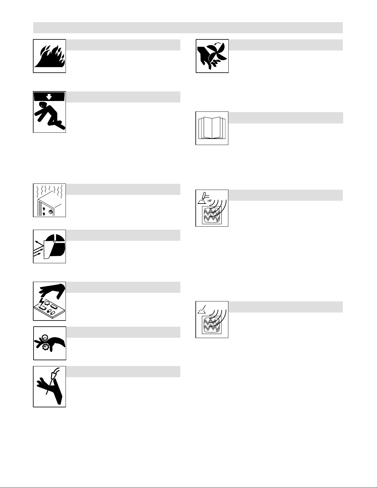
Warning! Watch Out! There are possible
hazards as shown by the symbols.
1 Electric shock can kill.
1.1 Wear dry insulating gloves. Do not
touch electrode with bare hand. Do
not wear wet or damaged gloves.
1.2 Protect yourself from electric shock
by insulating yourself from work and
ground.
1.3 Disconnect input plug or power
before working on machine.
2 Breathing welding fumes can be
hazardous to your health.
2.1 Keep your head out of the fumes.
2.2 Use forced ventilation or local
exhaust to remove the fumes.
2.3 Use ventilating fan to remove fumes.
3 Welding sparks can cause explosion
or fire.
3.1 Keep flammables away from welding.
Do not weld near flammables.
3.2 Welding sparks can cause fires.
Have a fire extinguisher nearby, and
have a watchperson ready to use it.
3.3 Do not weld on drums or any closed
containers.
4 Arc rays can burn eyes and injure
skin.
4.1 Wear hat and safety glasses. Use
ear protection and button shirt collar.
Use welding helmet with correct
shade of filter. Wear complete body
protection.
5 Become trained and read the
instructions before working on the
machine or welding.
6 Do not remove or paint over (cover)
the label.
2-2. WEEE Label
Do not discard this product with
general waste.
Reuse or recycle Waste Electrical
and Electronic Equipment (WEEE)
by disposing at a designated collection facility.
Contact your local recycling office
or your local distributor for further
information.
OM-244 243 Page 5
Page 10
1
2
6 7
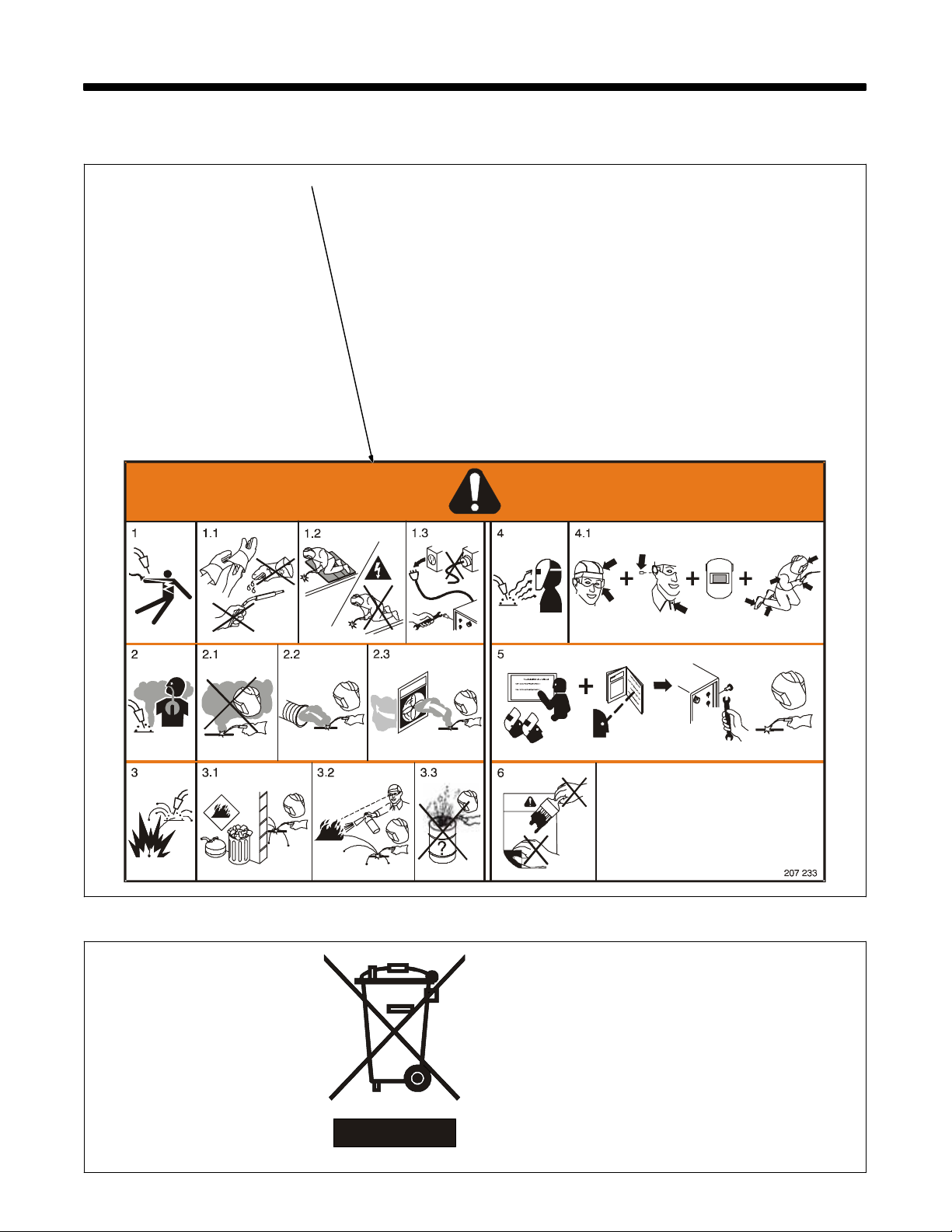
Warning! Watch Out! There are
possible hazards as shown by the
symbols.
1 Electric shock from wiring can
kill.
2 Disconnect input plug or
power before working on
machine.
3
45
3 Hazardous voltage remains
on input capacitors after
power is turned off. Do not
touch fully charged
capacitors.
V
V
> 60 s
V
4 Always wait 60 seconds after
power is turned off before
working on unit, OR
5 Check input capacitor voltage,
and be sure it is near 0 before
touching any parts.
6 When power is applied failed
S-185 836
parts can explode or cause
other parts to explode.
7 Flying pieces of parts can
8
9
cause injury. Always wear a
face shield when servicing
unit.
8 Always wear long sleeves and
button your collar when
servicing unit.
9 After taking proper
precautions as shown,
connect power to unit.
Warning! Watch Out! There are
possible hazards as shown by the
symbols.
Electric shock from wiring can kill.
Disconnect input plug or power
before working on machine.
Read the Owner’s Manual before
working on this machine.
1 Consult rating label for input
power requirements, and
check power available at the
job site − they must match.
2 Read Owner’s Manual and
inside labels for connection
points and procedures.
3 Not Applicable
4 Having a loop of extra length,
connect grounding conductor
first.
5 Not Applicable
OM-244 243 Page 6
Page 11
21 3
100 h. std.
4
5
=
6
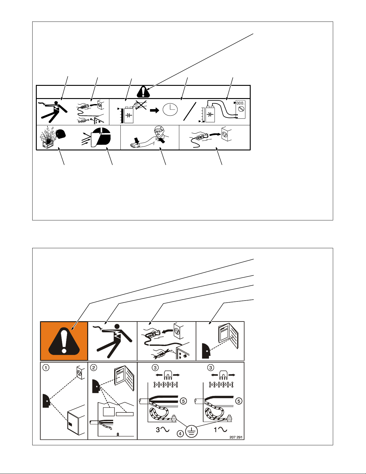
1 Warning! Watch Out! There are
possible hazards as shown by the
symbols.
2 Disconnect input plug or power before
working on machine.
1
3 Wear approved safety glasses with
side shields while working on the unit.
4 Plugged filter or hoses can cause
overheating to the power source and
torch.
1
7
(B) 050024004
956 142 617
5 Every 100 hours, check and clean filter
and check condition of hoses.
6 Read Owner’s Manual.
7 Use coolant suggested by
manufacturer.
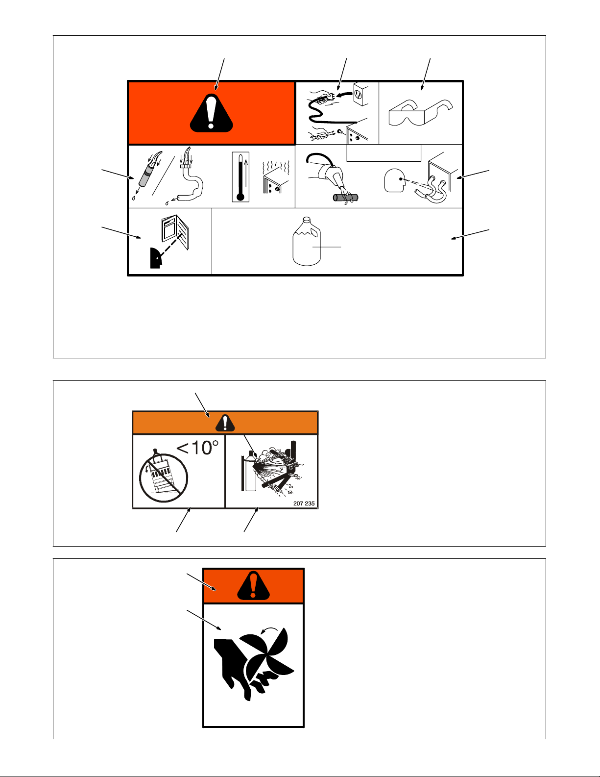
1 Warning! Watch Out! There
are possible hazards as
shown by the symbols.
2 Falling unit can cause injury.
Do not move or operate unit
where it could tip.
3 Cylinders can expolde if
damaged. Protect
compressed gas cylinders
from excessive heat,
mechanical shock, slag, open
flames, sparks, and arcs.
23
1
2
S-176 106
1 Warning! Watch Out! There
are possible hazards as
shown by the symbols.
2 Moving parts can cause injury.
Keep away from moving parts
such as fans.
OM-244 243 Page 7
Page 12
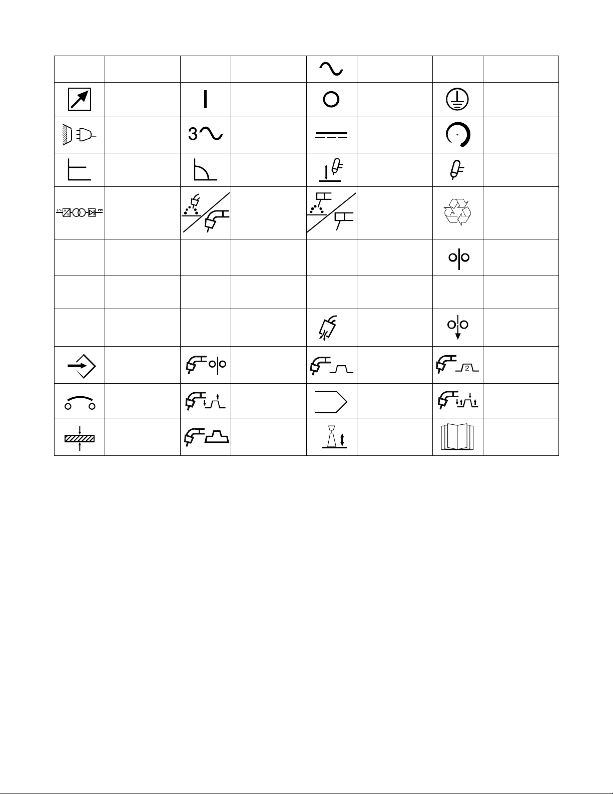
2-3. Symbols And Definitions
A
U
U
U
Amperage
Remote On Off
Line connection Three Phase
Constant Voltage Constant Current
Three Phase Static
Frequency Con-
verter-
Transformer-
Rectifier
1
2
0
Primary Voltage
Conventional
Load Voltage
Rated No Load
Voltage (Average)
V
I
1max
I
IP
2
Voltage
Gas Metal Arc
Welding (GMAW)
Rated Maximum
Supply Current
Rated Welding
Current X
Degree Of
Protection
I
1eff
Alternating
Current (AC)
Direct Current
(DC)
Lift-Arc Operation
(GTAW)
Shielded Metal Arc
Welding (SMAW)
Maximum Effective
Supply Current
Duty Cycle
Purge Wire ’Jog’
Hz
%
Hertz
Protective Earth
(Ground)
Increase
Gas Tungsten Arc
Welding
Recycle or dispose
of used coolant in
an environmentally
safe way
Wire Feed Speed
Percent
Set-Up MIG Synergic
Circuit Breaker 2T Trigger Mode Memory Store 4T Trigger Mode
Material Thickness
Mini-Logic
Trigger Mode
. Symbols not shown here are detailed in this manual when they are relevant.
MIG Pulsed
Synergic Welding
Arc Length
(Trim)
MIG Double
Pulsed Synergic
Welding
Read Instructions
OM-244 243 Page 8
Page 13
SECTION 3 − INSTALLATION
3-1. Important Information Regarding CE Products (Sold Within The EU)
! This equipment shall not be used by the general public as the EMF limits for the general public might be exceeded during welding.
This equipment is built in accordance with EN 60974−1 and is intended to be used only in an occupational environment (where the general public
access is prohibited or regulated in such a way as to be similar to occupational use) by an expert or an instructed person.
Wire feeders and ancillary equipment (such as torches, liquid cooling systems and arc striking and stabilizing devices) as part of the welding
circuit may not be a major contributor to the EMF. See the Owner’s Manuals for all components of the welding circuit for additional EMF exposure
information.
S The EMF assessment on this equipment was conducted at 0.5 meter.
S At a distance of 1 meter the EMF exposure values were less than 20% of the permissible values.
3-2. Serial Number And Rating Label Location
The serial number and rating information for this product is located on the back panel. Use rating label to determine input power requirements and/or
rated output. For future reference, write serial number in space provided on back cover of this manual.
3-3. Specifications
Rated Welding
Output
300 A @
32 Volts DC,
60% Duty Cycle
*While idling
Voltage
Range
10 − 35 V 5 − 400 A 90 23S
Amperage
Range
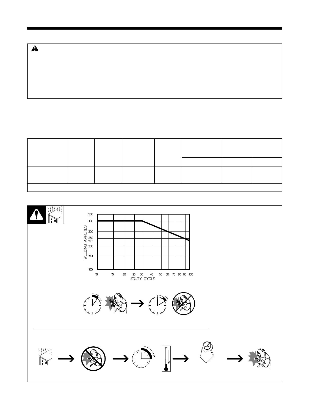
3-4. Duty Cycle And Overheating
Maximum
Open-Circuit
Voltage DC
60% Duty Cycle
IP Rating
Amperes Input
at Rated Load
Output 50/60 Hz
400 V KVA KW
17.0
(0,15*)
Duty Cycle is percentage of 10 minutes that unit can weld at rated load
without overheating.
If unit overheats, output stops, a
Help message is displayed, and
cooling fan runs. Wait fifteen minutes for unit to cool. Reduce amperage or duty cycle before welding.
NOTICE − Exceeding duty cycle
can damage unit and void warranty.
12.4
(0,09*)
11.5
(0,04*)
Overheating
6 Minutes Welding 4 Minutes Resting
0
15
Minutes
A
OR
Reduce Duty Cycle
Ref. SA-178 651
OM-244 243 Page 9
Page 14
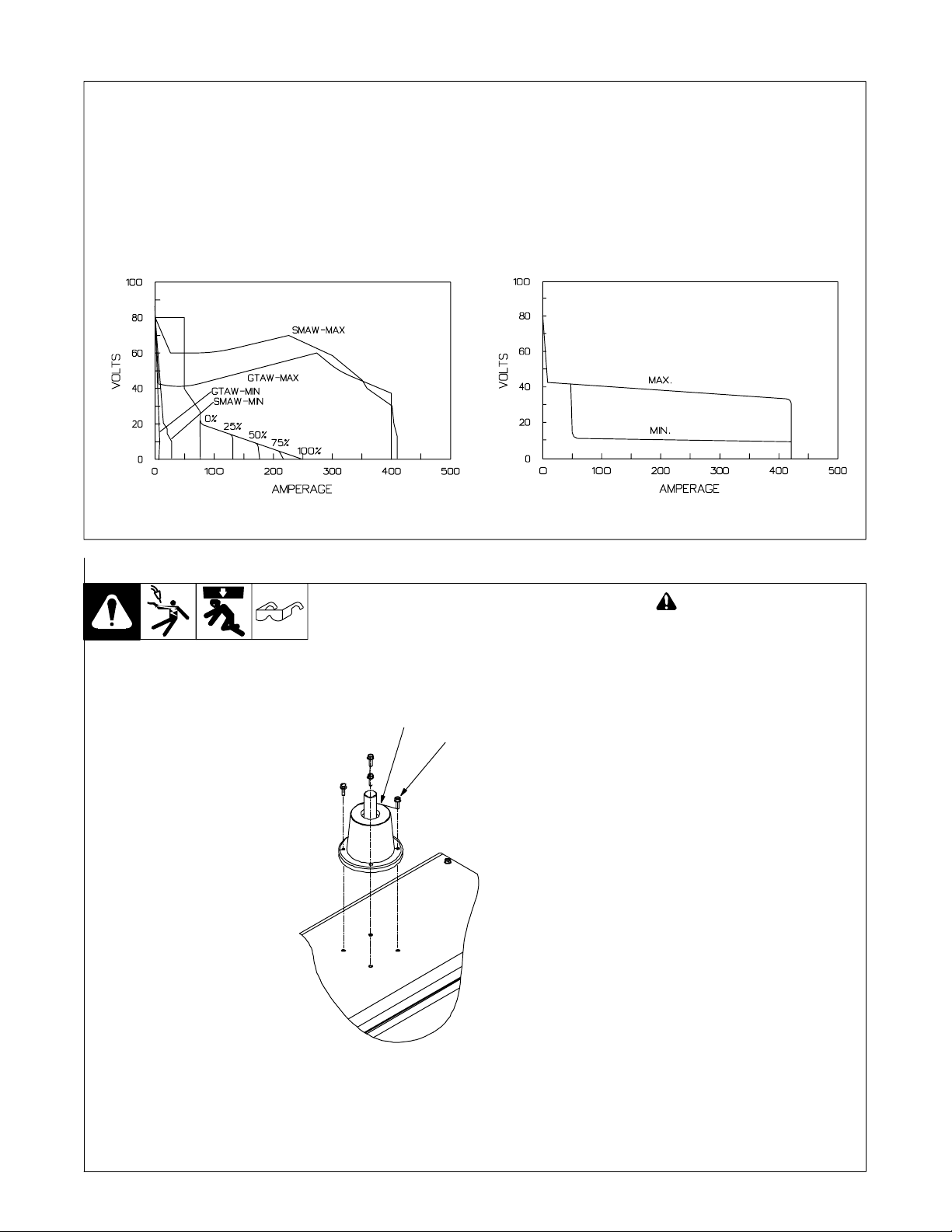
3-5. Volt-Ampere Curves
Volt-ampere curves show minimum
and maximum voltage and amperage output capabilities of unit.
Curves of other settings fall between curves shown.
A. CC Mode
ARC CONTROL
B. CV Mode
va_curve1 4/95 − SA-178 652 / SA-178 653
3-6. Installing Turntable for Wire Feeder on Power Source (Optional)
! Turn off welding power
source and disconnect input power before proceeding.
Remove wire spool.
1 Turntable
1
2
2 Screw
Remove the 4 screws and the plastic cap on the power source upper
cover and keep them for future use.
Insert the turntable in the upper hole
and secure with 4 screws. Be sure
screws are tight.
If desired, install the wire feeder on
the turntable using the hole in the
bottom of the feeder.
OM-244 243 Page 10
Ref. 956142645-5-5
Page 15

3-7. Dimensions And Weight
Weight
90 kg (198 lb)
3-8. Selecting a Location
860 mm
(33.8 in.)
490 mm
(19.3 in.)
1010 mm
(39.7 in.)
Dimensions
Ref. 956142645-3-5
Location
1
500 mm
(19.7 in.)
2
500 mm
(19.7 in.)
1 Handle
Do not use handle to lift unit.
2 Line Disconnect Device
Locate unit near correct input
power supply.
! Special installation may be
required where gasoline or
volatile liquids are present −
see NEC Article 511 or CEC
Section 20.
Movement
! Do not move or operate unit
where it could tip.
500 mm
(19.7 in.)
500 mm
(19.7 in.)
Ref. 956142645-3-5
OM-244 243 Page 11
Page 16

3-9. Weld Output Terminals And Selecting Cable Sizes
NOTICE − The Total Cable Length in Weld Circuit (see table below) is the combined length of both weld cables. For example, if the power source is
100 ft (30 m) from the workpiece, the total cable length in the weld circuit is 200 ft (2 cables x 100 ft). Use the 200 ft (60 m) column to determine cable
size.
Weld Cable Size** and Total Cable (Copper) Length in Weld Circuit
Weld Output
Terminals
! Turn off power be-
fore connecting to
weld output terminals.
! Do not use worn,
damaged, undersized, or poorly
spliced cables.
Positive
receptacle
TIG/Stick
Positive
receptacle
MIG
30 m (100 ft) or Less
10 − 60%
mm
Duty
Cycle
2
(AWG)
Welding
Amperes
100 20 (4) 20 (4) 20 (4) 30 (3) 35 (2) 50 (1) 60 (1/0) 60 (1/0)
150 30 (3) 30 (3) 35 (2) 50 (1) 60 (1/0) 70 (2/0) 95 (3/0) 95 (3/0)
200 30 (3) 35 (2) 50 (1) 60 (1/0) 70 (2/0) 95 (3/0) 120 (4/0) 120 (4/0)
60 − 100%
Duty
Cycle
2
mm
(AWG)
(150 ft)
Not Exceeding***
45 m
60 m
(200 ft)
70 m
(250 ft)
90 m
(300 ft)
10 − 100% Duty Cycle
2
mm
(AWG)
105 m
(350 ft)
120 m
(400 ft)
250 35 (2) 50 (1) 60 (1/0) 70 (2/0) 95 (3/0) 120 (4/0)
300 50 (1) 60 (1/0) 70 (2/0) 95 (3/0) 120 (4/0)
350 60 (1/0) 70 (2/0) 95 (3/0) 120 (4/0)
400 60 (1/0) 70 (2/0) 95 (3/0) 120 (4/0)
Gas
500 70 (2/0) 95 (3/0) 120 (4/0)
Negative receptacle
MIG/TIG/Stick
* This chart is a general guideline and may not suit all applications. If cable overheats, use next size larger cable.
**Weld cable size is based on either a 4 volts or less drop or a current density of at least 300 circular mils per ampere.
***For distances longer than those shown in this guide, call a factory applications representative. Milan Ref. S-0007-G 2009−08
600 95 (3/0) 120 (4/0)
2x70
(2 ea. 2/0)
2x70
(2 ea. 2/0)
2x95
(2 ea. 3/0)
2x70
(2 ea. 2/0)
2x70
(2 ea. 2/0)
2x95
(2 ea. 3/0)
2x120
(2 ea. 4/0)
2x70
(2 ea. 2/0)
2x95
(2 ea. 3/0)
2x95
(2 ea. 3/0)
2x120
(2 ea. 4/0)
3x95
(3 ea. 3/0)
2x70
(2 ea. 2/0)
2x95
(2 ea. 3/0)
2x95
(2 ea. 3/0)
2x120
(2 ea. 4/0)
3x95
(3 ea. 3/0)
3x120
(3 ea. 4/0)
2x70
(2 ea. 2/0)
2x95
(2 ea. 3/0)
2x120
(2 ea. 4/0)
2x120
(2 ea. 4/0)
3x95
(3 ea. 3/0)
3x120
(3 ea. 4/0)
OM-244 243 Page 12
Page 17

3-10. Remote 7 Receptacle Information (TIG And Stick Only)
Socket Socket Information
1 +10 volts DC supply voltage to remote
2 GND Remote control circuit common
3 IREF 0 to 10 current control signal
4 Not used.
5 UP 0V/10V digital signal
6 Not used.
7-Pin Remote Receptacle
7 TYPE 0V/10V digital signal
. This remote receptacle cannot be used with a standard Miller remote control. A customer supplied remote control is required to use the remote
receptacle.
Some signals can be enabled when TIG or Stick welding. Contact Factory Authorized Service Agent for confirmation.
3-11. Circuit Breakers
Circuit breakers with numbers 7
and 10 are placed on the rear panel
1
2
of the welder as shown.
1 Circuit Breaker 7
Protects the auxiliary 115 volt AC
output from overload. The 115 volt
AC output powers the water cooling
unit inside the power source.
2 Circuit Breaker 10
Protects the auxiliary 24 volt AC
output from overload. The 24 volt
AC output powers the wire feeder
inside the power source.
Ref. 956142645-4-5
OM-244 243 Page 13
Page 18

3-12. Filling Coolant Tank
. Operating cooler when coolant
is low can damage cooler and
torch components. Always
have proper amount of coolant
in tank and use coolant recommended by the manufacturer.
1 Coolant Tank Cap
2 Coolant Level Indicator
. Remove shielding gas cylinder
from rear of unit to fill coolant
1
2
Rear View
tank.
Unscrew cap from tank.
Use table to select proper coolant,
and fill tank until coolant appears in
upper half of indicator.
Check coolant level after attaching
torch coolant hoses and running
cooler. Be sure coolant appears in
upper half of indicator. Add coolant
if necessary.
Application
Coolant
*HF: High Frequency Current
**MILLER coolants protect to -37° F (-38°C) and resist algae growth.
NOTICE − Use of any coolant other than those listed in the table voids the warranty on any parts
that come in contact with the coolant (pump, radiator, etc.).
GTAW Or Where
HF* Is Used
MILLER Low Conductivity
Coolant No. 043 810**;
Distilled Or Deionized Water
OK Above 32° F (0° C)
3-13. Electrical Service Guide
GMAW Or Where
HF* Is Not Used
MILLER Low Conductivity
Coolant No. 043 810**; Or
MILLER Aluminum Protecting
Coolant No. 043 809**;
Distilled Or Deionized Water
OK Above 32° F (0° C)
Where Coolant Contacts
Aluminum Parts
MILLER Aluminum
Protecting Coolant
No. 043 809**
Ref. 956142645-4-5
Elec Serv 2009−08
. Actual input voltage should not exceed ± 10% of indicated required input voltage. If actual input voltage is outside of this range, output may not
be available.
50/60 Hz Three Phase
Input Voltage (V) 400
Input Amperes (A) At Rated Output 17
Max Recommended Standard Fuse Rating In Amperes
Time-Delay Fuses
Normal Operating Fuses
Min Input Conductor Size In mm2,
Max Recommended Input Conductor Length In Meters 41
Min Grounding Conductor Size In mm2,
Reference: 2008 National Electrical Code (NEC) (including article 630)
1 If a circuit breaker is used in place of a fuse, choose a circuit breaker with time-current curves comparable to the recommended fuse.
2 “Time-Delay” fuses are UL class “RK5”. See UL 248.
3 “Normal Operating” (general purpose - no intentional delay) fuses are UL class “K5” (up to and including 60 amps), and UL class “H” ( 65 amps and
above).
4 Conductor data in this section specifies conductor size (excluding flexible cord or cable) between the panelboard and the equipment per NEC Table
310.16. If a flexible cord or cable is used, minimum conductor size may increase. See NEC Table 400.5(A) for flexible cord and cable requirements.
OM-244 243 Page 14
4
4
1
2
3
20
25
2.5
2.5
Page 19

3-14. Connecting 3-Phase Input Power
3
Installation must meet all National
and Local Codes − have only qualified persons make this installation.
Disconnect and lockout/tagout input power before connecting input
conductors from unit.
Always connect green or green/
yellow conductor to supply
grounding terminal first, and never to a line terminal.
= GND/PE Earth Ground
4
7
2
L1
3
6
1
L2
L3
5
For Three-Phase Operation
1 Input Power Cord.
2 Disconnect Device (switch shown in
the OFF position)
3 Green Or Green/Yellow Grounding
Conductor
4 Disconnect Device Grounding
Terminal
5 Input Conductors (L1, L2 And L3)
6 Disconnect Device Line Terminals
Connect green or green/yellow grounding
conductor to disconnect device grounding
terminal first.
Connect input conductors L1, L2, and L3
to disconnect device line terminals.
7 Over-Current Protection
Select type and size of over-current
protection using Section 3-13 (fused disconnect switch shown).
Close and secure door on disconnect
device. Remove lockout/tagout device,
and place switch in the On position.
Tools Needed:
input2 2008−01 − 803 766-C / 956142645-3-5
OM-244 243 Page 15
Page 20

SECTION 4 − OPERATION
4-1. Front Panel Controls
8
16
10
12
14
9
17
1
2
11
13
15
18
19
20
4
5
3
7
1 ON/OFF Switch (I/O)
Use switch to turn unit On/Off.
. The power source cooling fan is
thermally controlled running only as required (Fan On Demand).
. Water cooling unit operation can be set
to function as required (auto) (Cooling
On Demand) “ON or OFF”.
2 Positive Power Connection for TIG
and Stick Welding.
. Do not use for MIG welding.
3 Negative Power Connection for all
welding processes.
4 Remote Control Receptacle for TIG
and Stick welding
5 Gas Connector (TIG Process)
6 Red Quick Connect Fitting
Coolant return from torch.
7 Blue Quick Connect Fitting
OM-244 243 Page 16
Coolant output to torch.
8 Handle
9 Control Panel
10 D1 (Display 1)
Displays values and parameters for selected welding process. During welding it
displays actual arc voltage.
11 D2 (Display 2)
Displays values and parameters for selected welding process. During welding it
shows measured welding current.
12 E1 (Encoder Control 1)
Use control to change values and parameters that appear on display D1.
13 E2 (Encoder Control 2)
Use control to change values and parameters that appear on display D2.
14 P1 (Memory Push Button)
Permits storage of welding parameters into
4 locations (TIG and Stick only).
6
Ref. 956142645-5-5
15 P2 (Setup Push Button)
Allows selecting setup or advanced programming menus.
16 P3 (Process Push Button)
Allows selecting welding process.
17 P4 (Material Push Button)
Allows selecting material type for synergic
MIG and synergic pulsed MIG processes.
18 P5 (Wire Diameter Push Button)
Selects desired welding wire diameter for
synergic MIG and synergic pulsed MIG
processes.
19 P6 (Gas Selection Push Button)
Selects desired welding gas type for synergic MIG and synergic pulsed MIG processes.
20 P7 (Trigger Selection Push Button)
Selects desired trigger mode in TIG welding and enables weld output for Stick welding (Default = OFF).
Page 21

4-2. Switching On the Unit and Recalling Factory Parameters
1
. Write down any parameters that
need to be restored before performing this procedure.
1 Power Switch
Use power switch to turn unit On.
When XMS 403 appears on D1 and
D2, press P3 and P8 simultaneously.
When MEMO CLEAR appears on
D1 and D2, release P3 and P7.
Wait until DONE appears on D1, and
turn unit Off.
The next time unit is turned On, all
parameters will return factory default
settings.
P7P3
Ref. 956142645-5-5
OM-244 243 Page 17
Page 22

4-3. Welding Power Source Setup Menu
P1
P2
P1 - Welding Parameter Setup Button.
P2 - Power Source Setup Button.
Press and hold P1 and P2.
XMS 403 appears on D1 and D2 followed by UNIT - IPM.
Wire feed speed is displayed as
(IPM) inches per minute.
Rotating knob P2 scrolls through
the following options:
UNIT MPM - Wire feed speed is
displayed in Meters Per Minute.
UNIT CUR - Power source will display welding current.
UNIT THCK - Power source welding parameters will be chosen according to the gauge (thickness) of
material to be welded.
Rotating knob P1 scrolls through
the following options:
W-UN AUTO - Rotate P2 to select
water cooling unit mode. AUTO
(Default) ON (Continuous) or OFF
(Water cooling not required)
RCTY 1 - Selects function mode for
remote receptacle (TIG).
Rotating P2 selects the following:
RCTY 2 - Selects function mode for
remote receptacle (For future applications)
RCTY 3 - Selects function mode for
remote receptacle (For future applications)
RCTY 4 - Selects function mode for
remote receptacle (For future applications)
LANG ENG - Selects language
ENG = English (Default)
Rotating P2 selects the following:
LANG FRA - Selects language
FRA = French
LANG ITA - Selects language ITA
= Italian
LANG GER - Selects language
GER = German
LANG SPA - Selects language
SPA = Spanish
OM-244 243 Page 18
Ref. 956142645-5-5
Page 23

4-4. Remote Receptacle (RCTY)
1
4-5. Welding Process Selection
L1
1 7 Pin Remote Receptacle
L2
L3
L4
P3
L1 LED
L2 LED
L3 LED
L4 LED
P3 Push Button
Press P3 until desired process LED illuminates.
Values and parameters that appear on D1
and D2 are either factory default settings or
last settings entered for the selected process.
L1 selection is Manual MIG welding.
D1 value is welding voltage, default is
18.5V (range is 10 V to 50 V).
D2 value is wire feed speed, default is 5.0
m/min (range is 1 m/min to 20 m/min). See
Section 4-11.
L2 Synergic MIG welding (non-pulsed).
D1 value is welding voltage, default is 16.5
V (range is −10 V to 50 V).
D2 value is the unit of measure as determ-
ined in the setup menu. (IPM, MPM, Current and Thickness)
. When L2 LED is stable the welding arc
is in a Short Circuit or Spray Arc transfer. If L2 is flashing this indicates that
the welding parameters are outside of
the specific setting required for either
arc transfer to exist. This process is
known as Globular Arc transfer. This
process produces considerable undesirable welding spatter. It may be desirable to switch to a Pulsed-MIG Arc
transfer to reduce/eliminate welding
spatter.
L3 Synergic Pulsed MIG welding.
Ref. 956142645-5-5
D1 value is welding voltage, default is 20
V (range is −10 V to 50 V).
D2 value is the unit of measure as determined in the setup menu. (IPM, MPM, Current and Thickness)
L4 Lift-TIG process (see Section 4-16) or
Stick process (see Section 4-17).
If selected process is TIG:
D1 displays TIG, and D2 value is welding
current, default is 220 A (range is 10 A to
400 A).
If selected process is Stick:
D1 displays Stick welding. Output is not enabled until button P7 is set to Output enabled mode. Display D1 displays open circuit voltage (OCV) at approximately 85
VDC. Display D2 displays welding current,
default is 220 A (range is 10 A to 400 A).
OM-244 243 Page 19
Page 24

4-6. Wire Type Selection in Synergic MIG or Synergic Pulsed MIG Welding
L5
L6
L7
L8
P4
Ref. 956142645-5-5
L5 LED
L6 LED
L7 LED
L8 LED
P4 Push Button
Press P4 until desired material LED illuminates. D1 and D2 will show material name
only momentarily, and then return to the
main display.
. D1 and D2 will show NO PROG or a
selection will not be allowed when there
is no program for the process, material,
wire diameter, and shielding gas combination.
L5 selection is for carbon steel.
L6 selection is for stainless steel.
L7 selection is for aluminum.
L8 selection is for other wire types not provided by standard selection.
Pressing P2 push button after a selection is
made to allow choosing other wire types
within the main selection.
SG2/3 allows selecting SG2 or SG3.
CrNi allows selecting 308L, 309L, or 316L.
Al allows selecting AlMg (AlMg5) or AlSi
(AlSi5).
Special permits selection of cored wire or
special wire types. (Abbreviations for the
different wire types appear in displays D1
and D2).
. Wire type selection is retained in the
welding process memory until a new
selection is made.
4-7. Wire Diameter Selection In Synergic MIG Or Synergic Pulsed MIG Welding
L9
L10
L11
L12
P5
Ref. 956142645-5-5
L9 LED
L10 LED
L11 LED
L12 LED
P5 Push Button
Press P5 until desired wire diameter LED
illuminates.
OM-244 243 Page 20
. D1 and D2 will show NO PROG or a
selection will not be allowed when
there is no program for the process,
material, wire diameter, and shielding
gas combination.
L9 selection is for 0.8 mm diameter wire.
L10 selection is for 1.0 mm diameter wire.
L11 selection is for 1.2 mm diameter wire.
L12 selection is for other wire diameters not
provided by standard selection.
Pressing P2 push button after the special
selection is made to allow choosing other
wire diameters not available by standard
selection.
Page 25

4-8. Gas Selection in Synergic MIG or Synergic Pulsed MIG Welding
L13
Gas
P6
Ref. 956142645-5-5
L13 LED
P6 Push Button
Press P6 until gas LED illuminates. D1 and
D2 will show gas name momentarily. Rotate
E2 encoder to select desired gas type. After
a brief moment the the displays will return to
the main parameters.
. Displays D1 and D2 will display NO
4-9. Trigger Mode Selection (L-TIG and Stick Processes)
L14
L15
L16
L17
P7
PROG or alternate selection will not be
possible when either process, material,
wire diameter, and shielding gas combination is not permitted.
Ref. 956142645-5-5
. Always check and set a trigger mode.
If trigger mode is undefined for a welding process, select the desired mode.
L14 LED
L15 LED
L16LED
L17 LED
P7 Push Button
Trigger mode can be set for TIG only.
In TIG welding, pressing P7 will change the
trigger mode, but D1 and D2 will not change
values.
In Stick welding, pressing P7 will enable
welding (L17 ON, D1 shows open circuit
voltage (OCV) or weld voltage.
D2 displays pre-set welding current or actu-
al welding current. If welding output is disabled welding (L17 OFF, D1 displays
STICK and D2 displays set current).
Press P7 to select the desired trigger mode:
L14 ON selects 2T trigger mode.
When trigger is pressed, welding starts.
When trigger is released, welding stops.
L15 ON selects 4T trigger mode.
When trigger is pressed, welding starts at
initial current level (IN).
When trigger is released, welding current
increases to the set current level.
When trigger is pressed and held, welding
current decreases to the set final current
(FI-A) is achieved. Releasing trigger extinguishes welding arc.
L16 ON selects 3 levels trigger function.
When trigger is pressed, welding starts with
initial level of welding current (Level 1).
When trigger is released, welding current
increases to the set current level (Level 2).
When trigger is pressed a second time,
weld current decreases to the set current
level (Level 3) arc extinguishes.
During level 2 mode if the torch trigger is
pressed and held, welding current decreases to the set final-current level (FI-A).
Releasing trigger extinguishes welding arc.
. L16 trigger mode is useful for thin mate-
rials and for a crater fill sequence.
L17 ON: Weld output power is enabled
welding terminals are electrically live. Stick/
TIG process requires LED L17 to be enabled. LED L17 will illuminate when welding
output power is enabling MIG mode.
OM-244 243 Page 21
Page 26

4-10. Welding Parameter Setup Menu (Double Pulsed-MIG/L-TIG And Stick)
Press P2 to enter SET UP menu.
SET UP will appear on D1 and D2
momentarily changing to the selected process parameter values.
Setup permits the viewing and
changing of default parameters for
each process mode.
Double Pulsed-MIG (DP) Mode
D1 displays DP.
P2
D2 displays ON/OFF.
E1 changes the mode of D2.
L-TIG/STICK Mode
D1 displays the welding parameter.
D2 displays the parameter value.
E1 changes the welding parameter.
E2 changes the parameter value.
. Incorrect settings in any pro-
cess can result in a program
with undesirable weld characteristics. Setup should only be
used by operators familiar with
various welding processes and
parameters.
Ref. 956142645-5-5
4-11. Preparing Power Source For MIG (GMAW) Welding Process
To select MIG welding process, proceed as
follows:
. Follow safety precautions according to
Section 1.
Prepare unit according to Section 3.
Use the correct interconnecting cable to
connect power source unit to the wire feeder (see Wire Feeder manual).
Use a cable with a correct adapter, connect
gun to the MIG gun connector on wire feeder (see Wire Feeder manual).
Connect work clamp cable to the WORK
connector.
If using a water-cooled gun, connect input
coolant hose to blue quick connect fitting
and return coolant hose to red quick connect fitting.
. Check coolant level after attaching
torch coolant hoses and running cooler. Be sure coolant appears in upper
half of indicator. Add coolant if necessary (see Section 3-12).
Setting Cooler Status (see Section 4-3)
. To prevent damage to water-cooled
torch and components, be sure that
coolant is turned on.
If a remote control is desired, connect it to
the Remote Control receptacle on the wire
feeder (see Wire Feeder manual).
Turn unit On.
Allow time for unit to complete its start up
cycle.
Set MIG welding process using P3 push
button.
Ref. 956142645-5-5
OM-244 243 Page 22
Page 27

4-12. Selecting Manual MIG Welding
P3
D1 D2
Ref. 956142645-5-5
Set Manual MIG welding process using P3
push button.
In Manual MIG mode, the operator may
need to adjust main welding parameters for
specific arc characteristics. Wire feed
speed and arc voltage will appear on D1
and D2.
During Setting :
D1 value is default voltage setting of 18.5 V
(range is 10.0 V to 50.0 V).
D2 value is default wire feed speed setting
of 5.0 m/min (range is 1.0 m/min to 20.0
m/min).
During MIG Welding:
D1 value is Measured Welding Voltage in
Volts.
D2 value is Measured Welding Amperage
in Amperes.
See Wire Feeder manual for remaining
manual MIG settings.
OM-244 243 Page 23
Page 28

4-13. Selecting Synergic MIG Welding
E1 D1 D2 E2
Ref. 956142645-5-5
P3 P6P4 P5
Set Synergic MIG welding process using
P3 push button.
In Synergic MIG mode, the operator may
need to adjust welding data (wire type, wire
diameter, and gas type) and only one weld
parameter. Generally, wire feed speed is
adjusted and the synergic process automatically sets appropriate weld voltage.
Synergic welding also sets many secondary welding parameters automatically for
improved weld quality.
D1 value is default voltage setting (range is
P7
defined by wire type, wire diameter and gas
type selection).
D2 value is the default current setting
(range is defined by wire type, wire diameter and gas type selection).
During Synergic MIG Welding:
D1 value is Measured Welding Voltage in
Volts.
D2 value is Measured Welding Amperage
in Amperes.
See Wire Feeder manual for all remaining
Synergic MIG settings.
Select wire type using P4 push button.
Select wire diameter using P5 push button.
Select gas using P6 push button.
Select trigger mode using P7 push button.
See Wire Feeder manual for remaining
Synergic MIG settings.
Setting Cooler Status (see Section 4-3 )
. To prevent damage to water-cooled
torch and components, be sure that
coolant is turned on.
OM-244 243 Page 24
Page 29

4-14. Selecting Synergic Pulsed MIG Welding
E1 D1 D2 E2
Ref. 956142645-5-5
P3 P6P4 P5
Set Synergic Pulsed MIG welding process
using P3 push button.
Synergic Pulsed MIG welding is a high quality welding process that produces very
little spatter. This process works well on thin
metals such as stainless steel and aluminum.
In Synergic Pulsed MIG mode, the operator
may need to adjust welding data (wire type,
wire diameter, and gas type) and only one
weld parameter. Generally, wire feed speed
is adjusted and the synergic process automatically sets appropriate weld voltage.
Synergic welding also sets many secondary welding parameters automatically for
improved weld quality.
During Setting:
D1 value is the default voltage setting
(range is defined by wire type, wire diameter and gas type selection).
D2 value is the default current setting
(range is defined by wire type, wire diameter and gas type selection).
P7
During Synergic MIG Welding:
D1 value is Measured Welding Voltage in
Volts.
D2 Value is Measured Welding Amperage
in Amperes.
Select wire type using P4 push button.
Select wire diameter using P5 push button.
Select gas using P6 push button.
Select trigger mode using P7 push button.
See wire feeder manual for all the remaining
Synergic MIG settings.
Setting Cooler Status (see Section 4-3)
Setting Synergic Double Pulsed MIG
Welding
Some metals weld better using the Synergic Double Pulsed Welding process due to
the unique pulsing of the welding arc. Heat
generated in the workpiece is generally
lower and the arc characteristics produce a
better weld bead appearance especially on
aluminum. The Synergic Double Pulsed
MIG process allows control all parameters
to produce high quality welds on aluminum.
. Incorrect settings in Synergic Double
Pulsed Welding process can result in a
program with undesirable weld characteristics. Setup should only be used by
operators familiar with various welding
processes and parameters. In certain
applications standard Pulsed MIG
welding may be preferred.
Press P2 to enter setup menu.
D1 displays DP.
D2 default setting is OFF.
Use E2 to change D2 value to ON. This setting will enable or disable Double Pulsed
MIG Synergic welding.
. On power source, only Double pulse
enabling and disabling is possible. All
the remaining Double Pulse settings
are made on the wire feeder (see Wire
Feeder manual). From the wire feeder
it is possible to recall Synergic MIG,
Synergic Pulsed MIG and Synergic
Double Pulsed MIG programs (see
Wire Feeder manuals).
OM-244 243 Page 25
Page 30

4-15. Preparing Unit For TIG Welding
E1 D1 D2 E2
P2
To prepare unit for TIG welding, proceed as
follows:
Follow safety precautions according to
Section 1.
Prepare unit according Section 3.
Connect torch to the WORK connector 3
and the gas pipe to the gas connector 5.
Using a cable with a proper adapter, connect work clamp cable to the MIG gun connector.
If using a water-cooled torch, connect input
coolant hose to blue quick connect fitting
and return coolant hose to red quick connect fitting.
. Check coolant level after attaching
torch coolant hoses and running cooler. Be sure coolant appears in upper
half of indicator. Add coolant if necessary (see Section 3-12).
Turn unit On.
Allow time for unit to complete its start up
cycle.
Set TIG welding process using P3 push
button.
P3 P7
. If D1 does not display TIG proceed as
follows:
Press P2 setup button. D1 will display STK.
Rotating E2 encoder changes process to
TIG mode.
Purge air from torch gas hose using Torch
Trigger (Manual Purge).
Select trigger mode using P7 push button
(see Section 4-9).
Setting Initial And Final Current
Use E1 to change D1 to IN−A (Initial Current).
D2 value is default setting of 20 A (range is
5 A to 400 A).
Use E2 to change D2 value.
This parameter allows starting the welding
process at a lower initial amperage setting.
Use E1 to change D1 to FI−A (Final Current).
D2 value is default setting of 20 A (range is
5 A to 400 A).
Use E2 to change D2 value.
This parameter allows finishing the welding
process at a lower final amperage setting.
Ref. 956142645-5-5
Setting Slope-Up Time
Press P2 to enter SET UP menu.
Use E1 to change D1 to SLUP.
D2 default setting is 0.1 second (range is
0.0 seconds to 10.0 A).
Setting Slope-Down Time
Press P2 to enter SET UP menu.
Use E1 to change D1 to SLDW.
D2 value is default setting of 0.1 second
(range is 0.0 seconds to 10.0 A).
Setting Postflow
Press P2 to enter SET UP menu.
Use E1 to change D1 to POSG.
D2 value is default setting of 5.0 second
(range is 0.0 seconds to 50.0 seconds).
Use E2 to change D2 value.
Setting Cooler Status (see Section 4-3)
. To prevent damage to water-cooled
torch and components, be sure that
coolant is turned on.
Purge air from torch gas hose using Torch
Trigger (Manual Purge).
Select trigger mode using P7 push button.
OM-244 243 Page 26
Page 31

4-16. TIG Lift-Arc Welding
Do NOT Strike Like A Match!
“Touch”
1
1 − 2
Seconds
Lift-Arc Start
When process selector LED 4 is illuminated in TIG mode Lift-Arc TIG
is enabled.
1 TIG Electrode
2
2 Workpiece
Touch tungsten electrode to workpiece at weld start point, enable output and shielding gas with torch trigger, foot control, or hand control.
Hold electrode to workpiece for
1-2 seconds, and slowly lift elec-
trode. Arc is formed when electrode
is lifted.
Normal open-circuit voltage is not
present before tungsten electrode
touches workpiece; only a low
sensing voltage is present between
electrode and workpiece. The
solid-state output contactor does
not energize until after electrode is
touching workpiece. This allows
electrode to touch workpiece without overheating, sticking, or getting
contaminated.
Application:
Lift-Arc is used for the DCEN or AC
GTAW process when HF Start
method is not permitted, or to replace the scratch method.
Ref. S-156 279
4-17. Preparing Unit For Stick Welding
To select Stick welding process, proceed
as follows:
Follow safety precautions according to
Section 1.
Prepare unit according to Section 3.
Connect electrode holder to the Positive
power connector 2.
Connect work clamp cable to the negative
connector 3.
If a remote control is desired, connect it to
the Remote Control receptacle 4.
Turn unit On.
Allow time for unit to complete its start up
cycle.
Set Stick welding process using P3 push
button.
. If D1 does not display STK proceed as
follows:
Press P2 setup button. D1 will display TIG.
Rotating E2 encoder changes process to
STK mode.
HOT START Setting
To change HOT START setting, proceed
as follows:
Press P2 to enter SET UP menu.
Use E1 to change D1 to HOT.
D2 value is default setting of 20% (range is
0% to 100%).
Use E2 to change D2 value.
This parameter increases output amperage at the start of a weld to eliminate electrode sticking.
ARC FORCE Setting
To change ARC FORCE setting, proceed
as follows:
Press P2 to enter SET UP menu.
Use E1 to change D1 to ARC.
D2 value is default setting of 0% (range is
0% to 100%).
Use E2 to change D2 value.
When setting is increased, short-circuit
amperage at low arc voltage increases.
STUCK Setting
To change STUCK ON/OFF setting, proceed as follows:
Press P2 to enter SET UP menu.
Use E1 to change D1 to STUK.
D2 default setting is OFF
Use E2 to change D2 to ON.
This parameter prevents the wire from
sticking at the start of the weld
. STICK welding can be enabled (L20
ON) or disabled (L20 OFF) using P7
push button, and this status is retained
in the STICK welding process
memory.
OM-244 243 Page 27
Page 32

SECTION 5 − MAINTENANCE & TROUBLESHOOTING
5-1. Routine Maintenance
Replace
Damaged Or
Unreadable
Labels
Blow Out Inside
! Disconnect power
3 Months
6 Months
before maintaining.
Repair Or
Replace
Cracked
Cables
. Maintain more often
during severe conditions.
Replace Cracked
Torch Body
Repair Or Replace
Cracked Cables
And Cords
Clean
And
Tighten Weld
Connections
Replace
Cracked
Hoses
Blow Out Heat
Exchanger Fins
Change
Coolant (If
Using Water)
12 Months
Change Coolant (If
Using MILLER Coolant)
OM-244 243 Page 28
Page 33

5-2. Help Displays
. All directions are in reference to the front
of the unit. All circuitry referred to is
located inside the unit.
Help 0
Indicates shorted thermistor RT2 on left side
of unit. Contact a Factory Authorized Service
Agent.
Help 1
Indicates a malfunction in the primary power
circuit. Contact a Factory Authorized Service
Agent.
Help 2
Indicates a malfunction in the thermal protection circuitry on left side of unit. Contact a
Factory Authorized Service Agent.
Help 3
Indicates overheating on left side of unit. Unit
will shutdown and fan will run until internal
temperature drops within operational range.
5-3. Troubleshooting
Help 4
Indicates a malfunction in the thermal protection circuitry on right side of unit. Contact a
Factory Authorized Service Agent.
Help 5
Indicates overheating on right side of unit.
Unit will shutdown and fan will run until internal temperature drops within operational
range.
Help 6
Indicates input voltage is too low and unit has
automatically shut down. Operation will continue when voltage is within an acceptable
lower range limit (15% below acceptable input voltage). Contact an electrician to check
input line voltage.
Help 7
Indicates input voltage is too high and unit
has automatically shut down. Operation will
continue when voltage is within an acceptable upper range limit (15% above acceptable input voltage). Contact an electrician to
check input line voltage. HELP 7 may also indicate a bus voltage imbalance.
Help 8
Indicates a malfunction in the secondary
power circuit of the unit. Contact a Factory
Authorized Service Agent.
Help 9
Indicates a shorted thermistor RT1 on right
side of unit. Contact a Factory Authorized
Service Agent.
Help 15
Indicates a malfunctioning cooling unit. Unit
will shut down immediately. Turn off primary
power. Check and repair cooling unit components as necessary. Unit will operate when
power to unit is turned off and back on.
Help 50
Indicates an overload at the power module.
Reduce weld parameter settings and/or duty
cycle. If error continues, contact a Factory
Authorized Service Agent.
Trouble Remedy
No weld output: unit completely inoperative.
No weld output; meter display On.
Erratic or improper weld output.
Coolant system not working (HELP 15
is displayed).
Reduced or no coolant flow from cooling unit (HELP 15 can be displayed).
Place line disconnect switch in On position (see Section 3-13).
Check and replace line fuse(s), if necessary, or reset circuit breaker (see Section 3-13).
Check for proper input power connections (see Section 3-13).
Verify welding parameter settings.
Verify Help messages and correction procedures as necessary.
Check, repair, or replace remote control.
Unit overheated. Allow fan to run and unit cool (see Section 3-4).
Use proper size and type of weld cable (see Section 3-9).
Clean and tighten all weld connections.
Check and secure coolant hose connectors.
Reset circuit breaker CB7 (see Section 3-11).
Motor overheated. Allow motor to cool and restart operation.
Have Factory Authorized Service Agent check cooling unit.
Add coolant.
Check for blockage at hoses.
Control panel not functioning properly.
Software problems.
Switch unit off and back on again to verify LEDs and display status.
Reinstall factory parameters (see Section 4-2).
Contact a Factory Authorized Service Agent.
OM-244 243 Page 29
Page 34

SECTION 6 − ELECTRICAL DIAGRAM
OM-244 243 Page 30
Figure 6-1. Circuit Diagram For XMS 403
Page 35

956142623
OM-244 243 Page 31
Page 36

SECTION 7 − PARTS LIST
. Hardware is common and
not available unless listed.
21
20
19
5
4
3
22
23
8
7
6
9
10
11
12
13
14
2
1
15
16
18
17
12
956142645A-1-5
OM-244 243 Page 32
Figure 7-1. Unit Outer Assembly
Page 37

Item
No.
Dia.
Mkgs.
Part
No.
Description
Figure 7-1. Unit Outer Assembly
1 +V17031284 Wrapper 1. . . . . . . . . . . . . . . . . . . . . . . . . . . . . . . . . . . . . . . . . . . . . . . . . . . . . . . . . . . . . . . . . . . . . .
2 156012136 Turntable 1. . . . . . . . . . . . . . . . . . . . . . . . . . . . . . . . . . . . . . . . . . . . . . . . . . . . . . . . . . . . . . . . . . . . . . .
3 000207235 Label, Warning, Tilting 1. . . . . . . . . . . . . . . . . . . . . . . . . . . . . . . . . . . . . . . . . . . . . . . . . . . . . . . . . . . .
4 +156005098 Cylinder Rack, Upper Support 1. . . . . . . . . . . . . . . . . . . . . . . . . . . . . . . . . . . . . . . . . . . . . . . . . . .
5 956142616 Nameplate, Rear, Gas, 14 Pin & Fuse Terminals 1. . . . . . . . . . . . . . . . . . . . . . . . . . . . . . . . . . . . .
6 956142617 Nameplate, Rear, Water & Dinse 1. . . . . . . . . . . . . . . . . . . . . . . . . . . . . . . . . . . . . . . . . . . . . . . . . . .
7 956142621 Nameplate, Coolant Level 1. . . . . . . . . . . . . . . . . . . . . . . . . . . . . . . . . . . . . . . . . . . . . . . . . . . . . . . . .
8 156087017 Pin, Split 2. . . . . . . . . . . . . . . . . . . . . . . . . . . . . . . . . . . . . . . . . . . . . . . . . . . . . . . . . . . . . . . . . . . . . . . .
9 156009067 Washer 4. . . . . . . . . . . . . . . . . . . . . . . . . . . . . . . . . . . . . . . . . . . . . . . . . . . . . . . . . . . . . . . . . . . . . . . . .
10 056054075 Wheel, Rear, 250 o.d. 2. . . . . . . . . . . . . . . . . . . . . . . . . . . . . . . . . . . . . . . . . . . . . . . . . . . . . . . . . . . .
11 156012119 Axle, Rear Wheels 1. . . . . . . . . . . . . . . . . . . . . . . . . . . . . . . . . . . . . . . . . . . . . . . . . . . . . . . . . . . . . . .
12 000207233 Label, General Precautionary 2. . . . . . . . . . . . . . . . . . . . . . . . . . . . . . . . . . . . . . . . . . . . . . . . . . . . . .
13 +V16122287 Side Panel, R 1. . . . . . . . . . . . . . . . . . . . . . . . . . . . . . . . . . . . . . . . . . . . . . . . . . . . . . . . . . . . . . . . . .
14 V56142305 Nameplate, Front, Dinse Negativ 1. . . . . . . . . . . . . . . . . . . . . . . . . . . . . . . . . . . . . . . . . . . . . . . . . .
15 056054074 Wheel/Caster,Front 2. . . . . . . . . . . . . . . . . . . . . . . . . . . . . . . . . . . . . . . . . . . . . . . . . . . . . . . . . . . . . . .
16 V56142303 Nameplate, Front, Dinse Positiv 1. . . . . . . . . . . . . . . . . . . . . . . . . . . . . . . . . . . . . . . . . . . . . . . . . . .
17 000207291 Label, Primary Power Connections 1. . . . . . . . . . . . . . . . . . . . . . . . . . . . . . . . . . . . . . . . . . . . . . . . .
18 +V16122288 Side Panel, L 1. . . . . . . . . . . . . . . . . . . . . . . . . . . . . . . . . . . . . . . . . . . . . . . . . . . . . . . . . . . . . . . . . .
19 156018115 Nut 5/8 1. . . . . . . . . . . . . . . . . . . . . . . . . . . . . . . . . . . . . . . . . . . . . . . . . . . . . . . . . . . . . . . . . . . . . . . . .
20 057052044 Fitting, Hose Brs Barbed M 1/4Tbg x 5/8−18 SAE 1. . . . . . . . . . . . . . . . . . . . . . . . . . . . . . . . . . . .
21 057052045 Fitting, Quick Connector 1. . . . . . . . . . . . . . . . . . . . . . . . . . . . . . . . . . . . . . . . . . . . . . . . . . . . . . . . . .
22 057052043 Adapter 5/8 UNC−3/8 BSP 1. . . . . . . . . . . . . . . . . . . . . . . . . . . . . . . . . . . . . . . . . . . . . . . . . . . . . . . .
23 058066057 Gas, Connection Kit 1. . . . . . . . . . . . . . . . . . . . . . . . . . . . . . . . . . . . . . . . . . . . . . . . . . . . . . . . . . . . . .
Quantity
+When ordering a component originally displaying a precautionary label, the label should also be ordered.
To maintain the factory original performance of your equipment, use only Manufacturer’s Suggested
Replacement Parts. Model and serial number required when ordering parts from your local distributor.
OM-244 243 Page 33
Page 38

. Hardware is common and
not available unless listed.
58
66
65
64
63
17
16
57
56
34
32
33
60
59
55
54
53
52
51
15
14
11
49
23
50
24
48
25
47
26
61
27
28
49
38
62
39
40
29
30
41
31
32
42
33
46
45
44
43
34
7
5
4
3
2
OM-244 243 Page 34
35
10
9
6
8
6
1
13
12
22
32
21
20
19
18
36
37
956142645A-2-5
Figure 7-2. Unit Main Assembly
Page 39

Item
No.
Dia.
Mkgs.
Part
No.
Description
Figure 7-2. Unit Main Assembly
1 316005010 LEM, Support 1. . . . . . . . . . . . . . . . . . . . . . . . . . . . . . . . . . . . . . . . . . . . . . . . . . . . . . . . . . . . . . . . . . . .
2 000201531 Kit Diode, Power Module 1. . . . . . . . . . . . . . . . . . . . . . . . . . . . . . . . . . . . . . . . . . . . . . . . . . . . . . . . . .
3 000199840 Bus Bar, Diode 2. . . . . . . . . . . . . . . . . . . . . . . . . . . . . . . . . . . . . . . . . . . . . . . . . . . . . . . . . . . . . . . . . .
4 PC6 000185697 Circuit Card, Filter Board 1. . . . . . . . . . . . . . . . . . . . . . . . . . . . . . . . . . . . . . . . . . . . . . . . . . . . .
5 HD1 000182918 Transducer, Current 400A Module Supply V +/− 15V 1. . . . . . . . . . . . . . . . . . . . . . . . . . . . .
6 RT2 000173632 Thermistor, NTC 30k ohms 2. . . . . . . . . . . . . . . . . . . . . . . . . . . . . . . . . . . . . . . . . . . . . . . . . . .
7 PC1 000215042 Circuit Card, Control 1. . . . . . . . . . . . . . . . . . . . . . . . . . . . . . . . . . . . . . . . . . . . . . . . . . . . . . . . .
8 T1 000179616 Transformer, HF 1. . . . . . . . . . . . . . . . . . . . . . . . . . . . . . . . . . . . . . . . . . . . . . . . . . . . . . . . . . . . . .
9 L1 000173563 Inductor, Input 1. . . . . . . . . . . . . . . . . . . . . . . . . . . . . . . . . . . . . . . . . . . . . . . . . . . . . . . . . . . . . . . .
10 Z1 000173570 Stabilizer 1. . . . . . . . . . . . . . . . . . . . . . . . . . . . . . . . . . . . . . . . . . . . . . . . . . . . . . . . . . . . . . . . . . . . .
11 T2 000195829 Transformer, Control 1. . . . . . . . . . . . . . . . . . . . . . . . . . . . . . . . . . . . . . . . . . . . . . . . . . . . . . . . . . .
12 PM1,2 000233043 Kit, Transistor IGBT Module 1. . . . . . . . . . . . . . . . . . . . . . . . . . . . . . . . . . . . . . . . . . . . . . . .
13 SR1 000179629 Kit Diode, Power Module 1. . . . . . . . . . . . . . . . . . . . . . . . . . . . . . . . . . . . . . . . . . . . . . . . . . . . .
14 C1 000188446 Capacitor, Polyp Film .5Uf 900VDC 1. . . . . . . . . . . . . . . . . . . . . . . . . . . . . . . . . . . . . . . . . . . .
15 C3,4 000192935 Capacitor, Elctlt 2700Uf 450VDC 2. . . . . . . . . . . . . . . . . . . . . . . . . . . . . . . . . . . . . . . . . . . . . .
16 V16117300 Wind Tunnel Extension, Front 1. . . . . . . . . . . . . . . . . . . . . . . . . . . . . . . . . . . . . . . . . . . . . . . . . . . . .
17 V16117360 Wind Tunnel Extension, Rear 1. . . . . . . . . . . . . . . . . . . . . . . . . . . . . . . . . . . . . . . . . . . . . . . . . . . . .
18 156002045 Handle 1. . . . . . . . . . . . . . . . . . . . . . . . . . . . . . . . . . . . . . . . . . . . . . . . . . . . . . . . . . . . . . . . . . . . . . . . .
19 000213051 Plastic, Upper 1. . . . . . . . . . . . . . . . . . . . . . . . . . . . . . . . . . . . . . . . . . . . . . . . . . . . . . . . . . . . . . . . . . .
20 000193919 Knob, Pointer 2. . . . . . . . . . . . . . . . . . . . . . . . . . . . . . . . . . . . . . . . . . . . . . . . . . . . . . . . . . . . . . . . . . . .
21 V56032301 Nameplate, Front 1. . . . . . . . . . . . . . . . . . . . . . . . . . . . . . . . . . . . . . . . . . . . . . . . . . . . . . . . . . . . . . .
22 000176226 Switch, Power ON/OFF 1. . . . . . . . . . . . . . . . . . . . . . . . . . . . . . . . . . . . . . . . . . . . . . . . . . . . . . . . . . .
23 PC2 000212210 Circuit Card, Interconnect 1. . . . . . . . . . . . . . . . . . . . . . . . . . . . . . . . . . . . . . . . . . . . . . . . . . . .
24 V57084081 Circuit Card, Control 1. . . . . . . . . . . . . . . . . . . . . . . . . . . . . . . . . . . . . . . . . . . . . . . . . . . . . . . . . . . . .
25 V57084362 Circuit Card, Switch 1. . . . . . . . . . . . . . . . . . . . . . . . . . . . . . . . . . . . . . . . . . . . . . . . . . . . . . . . . . . . .
26 V16118291 Panel, Front 1. . . . . . . . . . . . . . . . . . . . . . . . . . . . . . . . . . . . . . . . . . . . . . . . . . . . . . . . . . . . . . . . . . . .
27 057028110 Remote Control 14 Pin 1. . . . . . . . . . . . . . . . . . . . . . . . . . . . . . . . . . . . . . . . . . . . . . . . . . . . . . . . . . . .
28 656026097 Hose, 5x8,5x940 Black Gas 1. . . . . . . . . . . . . . . . . . . . . . . . . . . . . . . . . . . . . . . . . . . . . . . . . . . . . . .
29 656026099 Hose, 6x11x470 Blu Water 1. . . . . . . . . . . . . . . . . . . . . . . . . . . . . . . . . . . . . . . . . . . . . . . . . . . . . . . .
30 656026102 Hose, 6x11x270 Red Water 1. . . . . . . . . . . . . . . . . . . . . . . . . . . . . . . . . . . . . . . . . . . . . . . . . . . . . . . .
31 000188192 Receptacle, Gas 1. . . . . . . . . . . . . . . . . . . . . . . . . . . . . . . . . . . . . . . . . . . . . . . . . . . . . . . . . . . . . . . . .
32 000208967 Receptacle, Dinse 3. . . . . . . . . . . . . . . . . . . . . . . . . . . . . . . . . . . . . . . . . . . . . . . . . . . . . . . . . . . . . . . .
33 556049402 Water Connection, Quick Connect 2. . . . . . . . . . . . . . . . . . . . . . . . . . . . . . . . . . . . . . . . . . . . . . . . . .
34 556049401 Water Connection, Quick Connect 2. . . . . . . . . . . . . . . . . . . . . . . . . . . . . . . . . . . . . . . . . . . . . . . . . .
35 M V56126046 Fan Assy 1. . . . . . . . . . . . . . . . . . . . . . . . . . . . . . . . . . . . . . . . . . . . . . . . . . . . . . . . . . . . . . . . . . .
36 V56005296 Support, Module, Fan 1. . . . . . . . . . . . . . . . . . . . . . . . . . . . . . . . . . . . . . . . . . . . . . . . . . . . . . . . . . . .
37 V16039294 Box Louver 1. . . . . . . . . . . . . . . . . . . . . . . . . . . . . . . . . . . . . . . . . . . . . . . . . . . . . . . . . . . . . . . . . . . . .
38 056082099 Radiator Assy 1. . . . . . . . . . . . . . . . . . . . . . . . . . . . . . . . . . . . . . . . . . . . . . . . . . . . . . . . . . . . . . . . . . .
39 656026100 Hose, 6x11x780 Blu Water 1. . . . . . . . . . . . . . . . . . . . . . . . . . . . . . . . . . . . . . . . . . . . . . . . . . . . . . . .
40 116117079 Plenum, Fan 1. . . . . . . . . . . . . . . . . . . . . . . . . . . . . . . . . . . . . . . . . . . . . . . . . . . . . . . . . . . . . . . . . . . .
41 156005141 Support, Radiator 1. . . . . . . . . . . . . . . . . . . . . . . . . . . . . . . . . . . . . . . . . . . . . . . . . . . . . . . . . . . . . . . .
42 056061066 Flow-Meter 1. . . . . . . . . . . . . . . . . . . . . . . . . . . . . . . . . . . . . . . . . . . . . . . . . . . . . . . . . . . . . . . . . . . . . .
43 656026111 Hose, 6x11x160 Red Water 2. . . . . . . . . . . . . . . . . . . . . . . . . . . . . . . . . . . . . . . . . . . . . . . . . . . . . . . .
44 V56031377 Support Switch, Pressure 1. . . . . . . . . . . . . . . . . . . . . . . . . . . . . . . . . . . . . . . . . . . . . . . . . . . . . . . .
45 556049398 Header 1. . . . . . . . . . . . . . . . . . . . . . . . . . . . . . . . . . . . . . . . . . . . . . . . . . . . . . . . . . . . . . . . . . . . . . . . .
46 V16006289 Base 1. . . . . . . . . . . . . . . . . . . . . . . . . . . . . . . . . . . . . . . . . . . . . . . . . . . . . . . . . . . . . . . . . . . . . . . . . .
47 000176106 Label, Fan Warning 1. . . . . . . . . . . . . . . . . . . . . . . . . . . . . . . . . . . . . . . . . . . . . . . . . . . . . . . . . . . . . .
48 116122306 Mounting Bracket, Tank Assy 1. . . . . . . . . . . . . . . . . . . . . . . . . . . . . . . . . . . . . . . . . . . . . . . . . . . . . .
49 656026098 Hose, 6x11x250 Blu Water 1. . . . . . . . . . . . . . . . . . . . . . . . . . . . . . . . . . . . . . . . . . . . . . . . . . . . . . . .
50 027042002 Tank, Water 8 Liter 1. . . . . . . . . . . . . . . . . . . . . . . . . . . . . . . . . . . . . . . . . . . . . . . . . . . . . . . . . . . . . . .
51 000166564 Filter, In−line Assy 1. . . . . . . . . . . . . . . . . . . . . . . . . . . . . . . . . . . . . . . . . . . . . . . . . . . . . . . . . . . . . . . .
52 V57011071 Pump Assy 1. . . . . . . . . . . . . . . . . . . . . . . . . . . . . . . . . . . . . . . . . . . . . . . . . . . . . . . . . . . . . . . . . . . . .
53 656026092 Hose, 6x11x350 Blu Water 1. . . . . . . . . . . . . . . . . . . . . . . . . . . . . . . . . . . . . . . . . . . . . . . . . . . . . . . .
54 WCP 057010059 Motor, 170W, 115 VAC 1. . . . . . . . . . . . . . . . . . . . . . . . . . . . . . . . . . . . . . . . . . . . . . . . . . . . .
55 V56118293 Panel, Intermediate 1. . . . . . . . . . . . . . . . . . . . . . . . . . . . . . . . . . . . . . . . . . . . . . . . . . . . . . . . . . . . .
56 CB2 000083432 Circuit Breaker, Man Reset 1P 10A 250VAC 1. . . . . . . . . . . . . . . . . . . . . . . . . . . . . . . . . . . .
57 CB1 000161078 Circuit Breaker, Man Reset 1P 7A 250VAC 1. . . . . . . . . . . . . . . . . . . . . . . . . . . . . . . . . . . . .
58 V56091091 Strain Relief, Primary Cord 1. . . . . . . . . . . . . . . . . . . . . . . . . . . . . . . . . . . . . . . . . . . . . . . . . . . . . . .
59 000228036 Valve, 24VAC 1 Way 1. . . . . . . . . . . . . . . . . . . . . . . . . . . . . . . . . . . . . . . . . . . . . . . . . . . . . . . . . . . . .
60 156076085 Receptacle, 14 Pin 1. . . . . . . . . . . . . . . . . . . . . . . . . . . . . . . . . . . . . . . . . . . . . . . . . . . . . . . . . . . . . . .
61 V56126161 Fan Assy, Radiator Cooling 115 V 1. . . . . . . . . . . . . . . . . . . . . . . . . . . . . . . . . . . . . . . . . . . . . . . . .
62 656026101 Hose, 6x11x590 Red Water 1. . . . . . . . . . . . . . . . . . . . . . . . . . . . . . . . . . . . . . . . . . . . . . . . . . . . . . . .
63 +V16118292 Panel, Rear 1. . . . . . . . . . . . . . . . . . . . . . . . . . . . . . . . . . . . . . . . . . . . . . . . . . . . . . . . . . . . . . . . . . .
OM-244 243 Page 35
Quantity
Page 40

Item
No.
64 T4 V58021080 Transformer, 400VAC 1. . . . . . . . . . . . . . . . . . . . . . . . . . . . . . . . . . . . . . . . . . . . . . . . . . . . . . . . .
65 220805 Nut 1. . . . . . . . . . . . . . . . . . . . . . . . . . . . . . . . . . . . . . . . . . . . . . . . . . . . . . . . . . . . . . . . . . . . . . . . . . . . . . . .
66 V57014066 Primary Cable, 4 Core 6,0 Mq 1. . . . . . . . . . . . . . . . . . . . . . . . . . . . . . . . . . . . . . . . . . . . . . . . . . . .
+When ordering a component originally displaying a precautionary label, the label should also be ordered.
To maintain the factory original performance of your equipment, use only Manufacturer’s Suggested
Replacement Parts. Model and serial number required when ordering parts from your local distributor.
Dia.
Mkgs.
Part
No.
Figure 7-2. Unit Main Assembly (Continued)
Description
Quantity
Notes
OM-244 243 Page 36
Page 41

Notes
229895
MATERIAL THICKNESS GAUGE
Page 42

Notes
SOCKET/WRENCH SELECTION TABLE
(U.S. STANDARD)
Specifications Socket or Wrench Size Specifications Socket or Wrench Size
Bolt
Diameter
1/4 in .250 in 3/8 in 7/16 in 6 mm .2362 in 10 mm 10 mm
5/16 in .3125 in 1/2 in 9/16 in 8 mm .3150 in 14 mm 14 mm
3/8 in .375 in 9/16 in 5/8 in 10 mm .3937 in 17 mm 17 mm
7/16 in .4375 in 5/8 in 3/4 in 12 mm .4724 in 19 mm 19 mm
1/2 in .500 in 3/4 in 13/16 in 14 mm .5512 in 22 mm 22 mm
9/16 in .5625 in 7/8 in 7/8 in 16 mm .6299 in 24 mm 24 mm
5/8 in .625 in 15/16 in 1 in 18 mm .7087 in 27 mm 27 mm
3/4 in .750 in 1-1/8 in 1-1/8 in 22 mm .8661 in 32 mm 32 mm
7/8 in .875 in 1-5/16 in 1-5/16 in 24 mm .9449 in 36 mm 36 mm
1 in 1.000 in 1-1/2 in 1-1/2 in
Decimal
Equivalent
Bolt Nut
SOCKET/WRENCH SELECTION TABLE
(METRIC)
Bolt
Diameter
U.S.
Decimal
Equivalent
Bolt Nut
Page 43

Effective January 1, 2009
This limited warranty supersedes all previous Miller warranties and is exclusive with no other
LIMITED WARRANTY − Subject to the terms and conditions
below, ITW Welding Products Italy warrants to its original retail
purchaser that new Miller equipment sold after the effective date
of this limited warranty is free of defects in material and
workmanship at the time it is shipped by Miller. THIS
WARRANTY IS EXPRESSLY IN LIEU OF ALL OTHER
WARRANTIES, EXPRESS OR IMPLIED, INCLUDING THE
WARRANTIES OF MERCHANTABILITY AND FITNESS.
Within the warranty periods listed below, Miller will repair or
replace any warranted parts or components that fail due to such
defects in material or workmanship. Miller must be notified in
writing within thirty (30) days of such defect or failure, at which
time Miller will provide instructions on the warranty claim
procedures to be followed.
Miller shall honor warranty claims on warranted equipment listed
below in the event of such a failure within the warranty time
periods. All warranty time periods start on the date the
equipment was delivered to the original retail purchaser, not to
exceed eighteen months after the equipment is shipped to an
International distributor.
1. 5 Years Parts — 3 Years Labor
* Original main power rectifiers limited to only include
SCRs, diodes, and discrete rectifier components
where applicable
* Inverters (Input and Output Rectifiers Only)
2. 3 Years — Parts and Labor
* Transformer/Rectifier Power Sources
* Plasma Arc Cutting Power Sources
* Semi-Automatic and Automatic Wire Feeders
* Inverter Power Sources (Unless Otherwise Stated)
* Water Coolant Systems (Integrated)
* Engine Driven Welding Generators
(NOTE: Engines are warranted separately by the
engine manufacturer.)
3. 2 Years — Parts and Labor
* Motor Driven Guns (w/exception of Spoolmate
Spoolguns)
* Process Controllers
* RFCS Foot Controls
* IHPS Power Sources and Coolers
* Water Coolant Systems (Non-Integrated)
* HF Units
* Running Gear/Trailers
* Field Options
(NOTE: Field options are covered under True Blue®
for the remaining warranty period of the product they
are installed in, or for a minimum of one year —
whichever is greater.)
4. 1 Year — Parts and Labor Unless Specified
* DC 253 & 403 Rectifier (April 06>)
* Migmatic 171 (April 06>)
5. 6 Months — Batteries
guarantees or warranties expressed or implied.
6. 90 Days — Parts
* MIG Guns
* Induction Heating Coils and Blankets
* Remote Controls
* Accessory (Kits)
* Replacement Parts (No labor)
* Spoolmate Spoolguns
* Canvas Covers
Miller’s True Blue® Limited Warranty shall not apply to:
1. Consumable components; such as contact tips,
cutting nozzles, contactors, brushes, slip rings, relays
or parts that fail due to normal wear.
2. Items furnished by Miller, but manufactured by others, such
as engines or trade accessories. These items are covered
by the manufacturer’s warranty, if any.
3. Equipment that has been modified by any party other than
Miller, or equipment that has been improperly installed,
improperly operated or misused based upon industry
standards, or equipment which has not had reasonable and
necessary maintenance, or equipment which has been
used for operation outside of the specifications for the
equipment.
MILLER PRODUCTS ARE INTENDED FOR PURCHASE AND
USE BY COMMERCIAL/INDUSTRIAL USERS AND PERSONS
TRAINED AND EXPERIENCED IN THE USE AND
MAINTENANCE OF WELDING EQUIPMENT.
In the event of a warranty claim covered by this warranty, the
exclusive remedies shall be, at Miller’s option: (1) repair; or (2)
replacement; or, where authorized in writing by Miller in
appropriate cases, (3) the reasonable cost of repair or
replacement at an authorized Miller service station; or (4)
payment of or credit for the purchase price (less reasonable
depreciation based upon actual use) upon return of the goods at
customer’s risk and expense. Miller’s option of repair or
replacement will be F.O.B., Factory at ITW Welding Products
Group Europe or F.O.B. at a Miller authorized service facility as
determined by Miller. Therefore no compensation or
reimbursement for transportation costs of any kind will be
allowed.
TO THE EXTENT PERMITTED BY LAW, THE REMEDIES
PROVIDED HEREIN ARE THE SOLE AND EXCLUSIVE
REMEDIES. IN NO EVENT SHALL MILLER BE LIABLE FOR
DIRECT, INDIRECT, SPECIAL, INCIDENTAL OR
CONSEQUENTIAL DAMAGES (INCLUDING LOSS OF
PROFIT), WHETHER BASED ON CONTRACT, TORT OR ANY
OTHER LEGAL THEORY.
ANY EXPRESS WARRANTY NOT PROVIDED HEREIN AND
ANY IMPLIED WARRANTY, GUARANTY OR
REPRESENTATION AS TO PERFORMANCE, AND ANY
REMEDY FOR BREACH OF CONTRACT TORT OR ANY
OTHER LEGAL THEORY WHICH, BUT FOR THIS
PROVISION, MIGHT ARISE BY IMPLICATION, OPERATION
OF LAW, CUSTOM OF TRADE OR COURSE OF DEALING,
INCLUDING ANY IMPLIED WARRANTY OF
MERCHANTABILITY OR FITNESS FOR PARTICULAR
PURPOSE, WITH RESPECT TO ANY AND ALL EQUIPMENT
FURNISHED BY MILLER IS EXCLUDED AND DISCLAIMED
BY MILLER.
milan_warr 2009−05
Page 44

Owner’s Record
Please complete and retain with your personal records.
Model Name Serial/Style Number
Purchase Date (Date which equipment was delivered to original customer.)
Distributor
Address
Country Zip/Postal Code
For Service
Contact a DISTRIBUTOR or SERVICE AGENCY near you.
Always provide Model Name and Serial/Style Number.
Contact your Distributor for:
Contact the Delivering Carrier to:
Welding Supplies and Consumables
Options and Accessories
Service and Repair
Replacement Parts
Owner’s Manuals
File a claim for loss or damage during
shipment.
For assistance in filing or settling claims, contact
your distributor and/or equipment manufacturer’s
Transportation Department.
ITW Welding Products Italy S.r.l.
Via Privata Iseo, 6/E
20098 San Giuliano
Milanese, Italy
Phone: 39 (0) 2982901
Fax: 39 (0) 298290-203
email: miller@itw−welding.it
ORIGINAL INSTRUCTIONS − PRINTED IN USA © 2009 Miller Electric Mfg. Co. 2009−01
 Loading...