

Page 1
I283
MFP9720152
Page 2

Table of Contents
1.0 Purpose........................................................................................................................... 3
2.0 General Requirements, Warnings and Limitations.......................................................... 3-4
2.1 General Fall Protection Requirements
2.2 System Warnings and Limitations
3.0 Xenon Kit Diagrams and Component Descriptions......................................................... 5-6
4.0 Installation of Xenon Horizontal Lifeline Kits................................................................... 7-11
4.1 Installation of D-Bolt Anchor to Beam or Structure
4.2 Installation of Universal Intermediate Brackets
4.3 Installation of Horizontal Lifeline Assembly
4.4 Tensioning Horizontal Lifeline
4.5 Installation of a Second Shock Absorber
5.0 Operation/Use of Xenon Shuttle on the Horizontal Lifeline............................................. 12
6.0 Fall Clearance................................................................................................................. 13-14
7.0 Training............................................................................................................................ 15
8.0 Inspection and Maintenance............................................................................................ 15
Labels.............................................................................................................................. 15
Inspection and Maintenance Log..................................................................................... 16
Warranty.......................................................................................................................... 17
2
Page 3
User Instructions - English
Thank You
Thank you for your purchase of Miller Fall Protection equipment. Miller brand products are produced to meet the highest
standards of quality at our ISO 9001 certied facility. Miller Fall Protection equipment will provide you with years of use when
cared for properly.
WARNING
All persons using this equipment must read, understand and follow all instructions. Failure to do so
may result in serious injury or death. Do not use this equipment unless you are properly trained.
Questions?
It is crucial that the authorized person/user of this fall protection equipment read and understand these instructions. In addition, it is the employer’s responsibility to ensure that all users are trained in the proper use, inspection, and maintenance of fall
protection equipment. Fall protection training should be an integral part of a comprehensive safety program.
Proper use of fall arrest systems can save lives and reduce the potential of serious injuries from a fall. The user must be
aware that forces experienced during the arrest of a fall or prolonged suspension may cause bodily injury. Consult a physician
if there is any question about the user’s ability to use this product. Pregnant women and minors must not use this product.
CALL
1.800.873.5242
1.0 Pur pose
For use along crane rail runways, loading bays/docks, machinery maintenance conveyors, rooftops, pipe racks, bridges, inside
sports arenas, and many industrial applications, the Xenon Permanent Horizontal Lifeline Kit provides fall protection that ultimately increases worker mobility, safety and productivity. The uniquely-designed Xenon Shuttle self-aligns to smoothly pass
through intermediate brackets for 100% connection to the system.
2.0 General Requirements, Warnings and Limitations
2.1 General Fall Protection Requirements
All warnings and instructions shall be provided to authorized
persons/users. Warnings and instructions must be read and
understood prior to using this equipment.
All authorized persons/users must reference the
regulations governing occupational safety, as well as
applicable standards. Xenon Kits meet OSHA and ANSI
A10.32-2004.
Proper precautions should always be taken to remove any
obstructions, debris, material, or other recognized hazards
from the work area that could cause injuries or interfere with
the operation of the system.
All equipment must be inspected before each use according
to the manufacturer’s instructions.
All equipment should be inspected by a qualied person on a
regular basis.
To minimize the potential for accidental disengagement, a
competent person must ensure system compatibility.
Equipment must not be altered in any way. Repairs must be
performed only by the equipment manufacturer, or persons or
entities authorized, in writing, by the manufacturer.
Any product exhibiting deformities, unusual wear, or
deterioration must be immediately discarded.
Any equipment subject to a fall must be removed from service.
The user shall have a rescue plan and the means at hand to
implement it when using this equipment.
Never use fall protection equipment for purposes other than
those for which it was designed. Fall protection equipment
should never be used for towing or hoisting.
Never remove product labels, which include important
warnings and information for the authorized person/user.
3
Page 4
User Instructions - English
2.2 System Warnings and Limitations
System Compatibility
Xenon Kits are designed for use with Miller approved components. Substitution or replacement with non-approved
component combinations, sub-systems, or both, may affect
or interfere with the safe function of each other and endanger the compatibility within the system. This incompatibility
may affect the reliability and safety of the total system.
Miller Fall Protection requires the use of a Miller full-body
harness and shock-absorbing lanyard or self-retracting lifeline/fall limiter with this system. All instructions and warnings
provided with the body wear and connecting device must be
read and understood before using the equipment.
Maximum Lifeline Span
The maximum lifeline span (from anchor to anchor, from
anchor to intermediate bracket, or from intermediate bracket
to intermediate bracket) is 30 ft. (9.1m). System kits are
available in lengths from 30 ft. (9.1m) to 510 ft. (155.5m).
Any lifeline system extending beyond 30ft. (9.1m), known as
a multiple-span system, requires intermediate brackets at a
maximum of 30 ft. (9.1m) intervals.
Capacity
Maximum capacity is two (2) workers [310lbs (140.6kg)
each] for a single shock absorber system and four (4)
workers [310lbs (140.6kg) each] for a double shock absorber
system. Capacity ratings assume the anchorage or structure
to which the horizontal lifeline kit is installed meets the load
requirements.
System Forces
The Xenon Kit is equipped with an inline shock absorber. In
the event of a fall, the shock absorber limits system forces.
Fall Arrest Forces
In conjunction with the Xenon Horizontal Lifeline System,
workers must use a Miller self-retracting lifeline/fall limiter or
a shock-absorbing lanyard, which limits maximum fall arrest
force imposed by the worker to 900lbf (4kN).
Free Fall
Personal fall arrest systems must be rigged to limit a free fall
to the shortest possible distance [6ft (1.8m) maximum].
Fall Clearance
Ensure that adequate clearance exists in your fall path to
avoid striking a lower level or other object (see 6.0 Fall
Clearance).
Environmental Hazards
Use of this equipment in areas where environmental
hazards exist may require additional precautions to limit the
possibility of injury to the user or damage to the equipment.
Hazards may include, but are not limited to, extreme
temperatures, caustic chemicals, corrosive environments,
high voltage power lines, explosive or toxic gases, moving
machinery, and sharp edges. Do not expose the equipment
to any hazard which it is not designed to withstand. Consult
the manufacturer in cases of doubt.
System Requirements
The Horizontal Lifeline System shall be designed, installed
and used, under the supervision of a qualied person,
as part of a complete personal fall arrest system, which
maintains a safety factor of at least two.
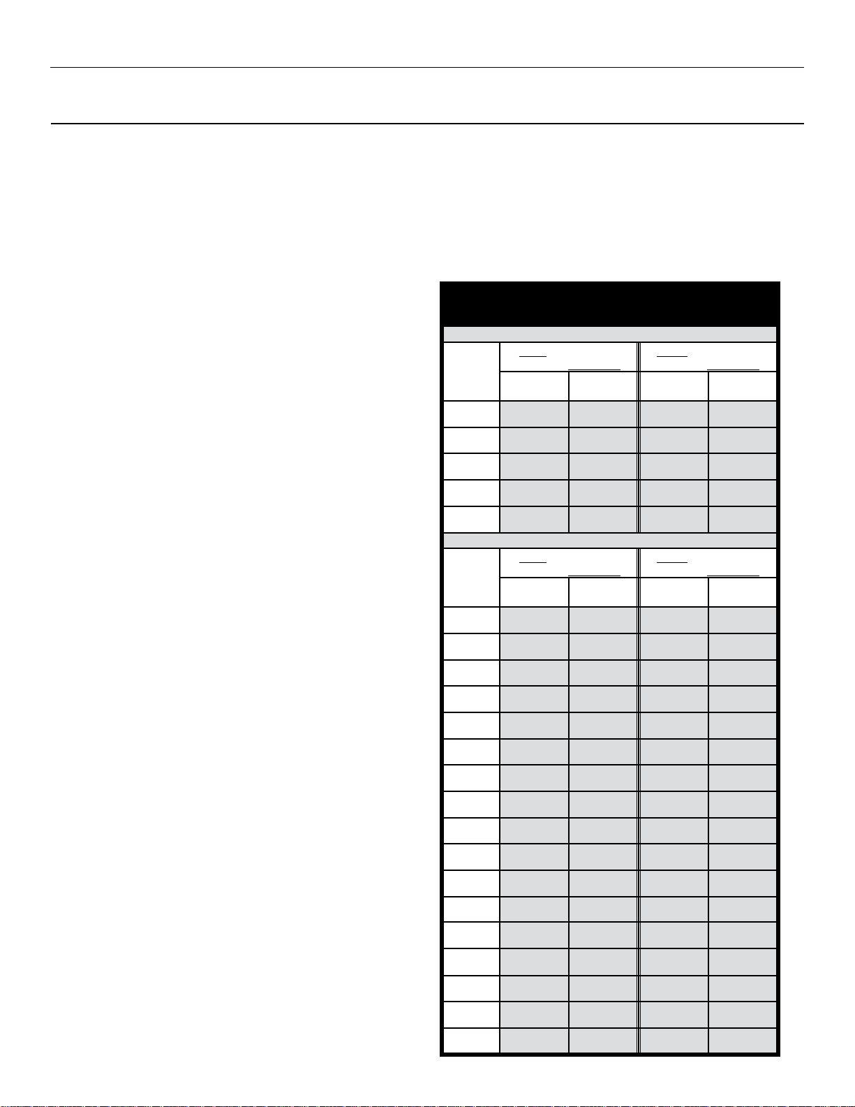
Ensure that there is adequate end and intermediate anchorage
strength for the Xenon HLL System per the chart below. *Load
requirements reect a 2:1 safety factor.
End and Intermediate System Load Requirements*
[lbf. (kN)] for Xenon HLL Systems
Single-Span Systems
System/
Span
Length
[ft. (m)]
10
(3m)
15
(4.5m)
20
(6.1m)
25
(7.6m)
30
(9.1m)
Multiple-Span Systems (with 30 ft. spans)
System
Length
[ft (m)]
30
(9.1m)
60
(18.2m)
90
(27.4m)
120
(36.5m)
150
(45.7m)
180
(54.8m)
210
(64m)
240
(73.1m)
270
(82.2m)
300
(91.4m)
330
(100.5m)
360
(109.7m)
390
(118.8m)
420
(128m)
450
(137.1m)
480
(146.3m)
510
(155.4m)
4
Single Shock Absorber
System for 1-2 Workers
End
Load
3294 lbf.
(14.7kN)
3786 lbf.
(16.8kN)
4330 lbf.
(19.3kN)
4686 lbf.
(20.8kN)
4968 lbf.
(22.1kN)
Single Shock Absorber
System for 1-2 Workers
End
Load
4968 lbf.
(22.1kN)
4692 lbf.
(20.9kN)
4458 lbf.
(19.8kN)
4302 lbf.
(19.1kN)
4132 lbf.
(18.4kN)
4006 lbf.
(17.8kN)
3906 lbf.
(17.4kN)
3794 lbf.
(16.9kN)
3718 lbf.
(16.5kN)
3640 lbf.
(16.2kN)
3574 lbf.
(15.9kN)
3504 lbf.
(15.6kN)
3442 lbf.
(15.3kN)
3388 lbf.
(15.1kN)
3342 lbf.
(14.9kN)
3290 lbf.
(14.6kN)
3242 lbf.
(14.4kN)
Intermediate
Intermediate
Load
2420 lbf.
(10.8kN)
2420 lbf.
(10.8kN)
2420 lbf.
(10.8kN)
2420 lbf.
(10.8kN)
2420 lbf.
(10.8kN)
Load
2420 lbf.
(10.8kN)
2420 lbf.
(10.8kN)
2420 lbf.
(10.8kN)
2420 lbf.
(10.8kN)
2420 lbf.
(10.8kN)
2420 lbf.
(10.8kN)
2420 lbf.
(10.8kN)
2420 lbf.
(10.8kN)
2420 lbf.
(10.8kN)
2420 lbf.
(10.8kN)
2420 lbf.
(10.8kN)
2420 lbf.
(10.8kN)
2420 lbf.
(10.8kN)
2420 lbf.
(10.8kN)
2420 lbf.
(10.8kN)
2420 lbf.
(10.8kN)
2420 lbf.
(10.8kN)
Double Shock Absorber
System for 3-4 Workers
End
Load
3790 lbf.
(16.9kN)
4374 lbf.
(19.5kN)
4910 lbf.
(21.8kN)
5342 lbf.
(23.8kN)
5812 lbf.
(25.9kN)
Double Shock Absorber
System for 3-4 Workers
End
Load
5812 lbf.
(25.9kN)
5556 lbf.
(24.7kN)
5344 lbf.
(23.8kN)
5192 lbf.
(23.1kN)
5034 lbf.
(22.4kN)
4910 lbf.
(21.8kN)
4840 lbf.
(21.5kN)
4716 lbf.
(21kN)
4638 lbf.
(20.6kN)
4550 lbf.
(20.2kN)
4490 lbf.
(20kN)
4414 lbf.
(19.6kN)
4364 lbf.
(19.4kN)
4304 lbf.
(19.2kN)
4248 lbf.
(18.9kN)
4196 lbf.
(18.7kN)
4148 lbf.
(18.5kN)
Intermediate
Load
3660 lbf.
(16.3kN)
3660 lbf.
(16.3kN)
3660 lbf.
(16.3kN)
3660 lbf.
(16.3kN)
3660 lbf.
(16.3kN)
Intermediate
Load
3660 lbf.
(16.3kN)
3660 lbf.
(16.3kN)
3660 lbf.
(16.3kN)
3660 lbf.
(16.3kN)
3660 lbf.
(16.3kN)
3660 lbf.
(16.3kN)
3660 lbf.
(16.3kN)
3660 lbf.
(16.3kN)
3660 lbf.
(16.3kN)
3660 lbf.
(16.3kN)
3660 lbf.
(16.3kN)
3660 lbf.
(16.3kN)
3660 lbf.
(16.3kN)
3660 lbf.
(16.3kN)
3660 lbf.
(16.3kN)
3660 lbf.
(16.3kN)
3660 lbf.
(16.3kN)
Page 5
User Instructions - English
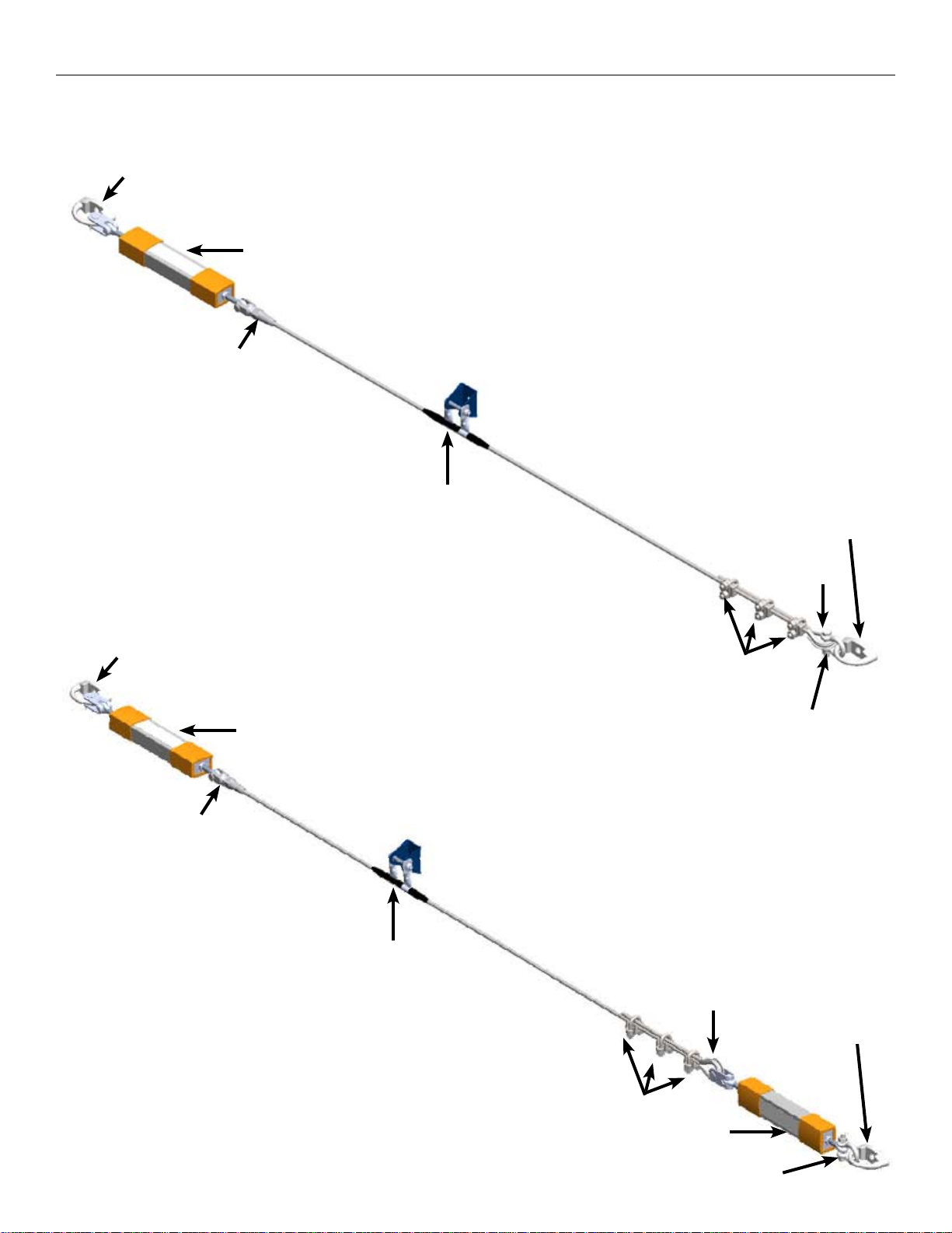
3.0 Xenon Kit Diagr ams and Component Descriptions
D-Bolt Anchor
Single Shock Absorber Xenon Kit
Shock Absorber
Swageless
Cable Fitting
Intermediate
Support Bracket
D-Bolt Anchor
D-Bolt Anchor
Swageless
Cable Fitting
Thimble
Cable Clips
Anchor Shackle
Shock Absorber
Intermediate
Support Bracket
Thimble
Double Shock Absorber Xenon Kit
D-Bolt Anchor
Cable Clips
Shock Absorber
5
5
Anchor Shackle
Page 6
User Instructions - English
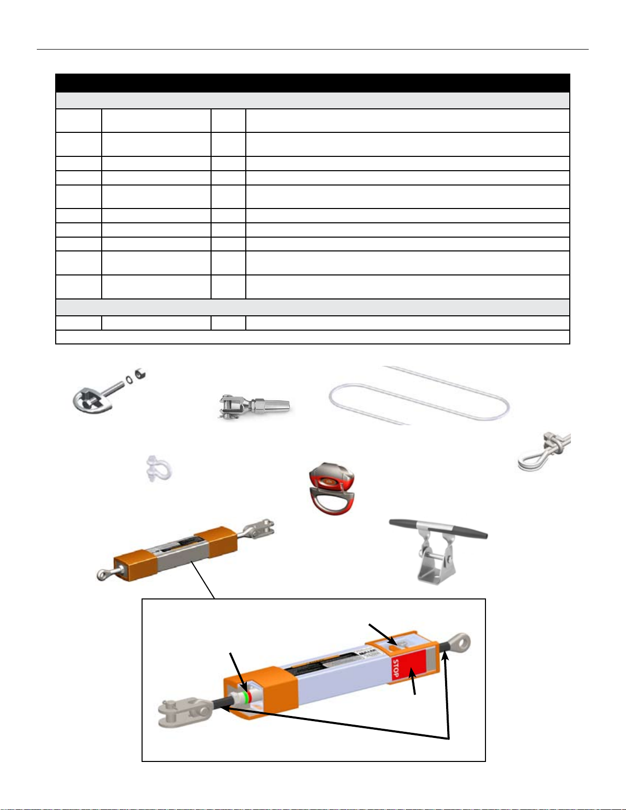
Part No. Component Name Qty. Description
System Kit Components
416SS D-Bolt Anchor 2
417SS D-Bolt Anchor 2
1014934 Xenon 4-in-1 Shock Absorber 1 or 2* Multi-purpose shock absorber acts as an inline shock absorber, turnbuckle, tension indicator and fall indicator
1013720 Fast Attach Cable Fitting 1 Stainless steel, swageless cable tting for 5/16" (8mm) wire rope
XC00030 Cable Lifeline 1
XP00001 Thimble 1 Stainless steel thimble
XP00002 Cable Clip 3 5/16” (8mm) wire rope clip
SGAS-SS Anchor Shackle 1 7/16” (11mm) stainless steel shackle with bolt, nut and cotter pin
1010608 Universal Intermediate Bracket Varies
1010609 Universal Intermediate Bracket Varies
Optional System Components
1005709 Xenon Shuttle Varies Shuttle with stainless steel attachment ring; self-aligns for smooth pass-through of intermediate brackets
*A second shock absorber may be added to accommodate three (3) to four (4) workers on the horizontal lifeline system.
5/8” (16mm) stainless steel D-anchor with hex bolt (5/8” - 11 UNC x 5”), hex nut and split lockwasher, rated
to 10,000 lbs. (45kN)
5/8" (16mm) stainless steel D-anchor, rated to 10,000 lbs. (45kN) (Fasteners not included--The 417 D-Bolt
Anchor must only be used with an approved 5/8" - 11 UNC hex bolt, hex nut and split lockwasher.)
5/16” (8mm) diameter stainless steel wire rope, 30' (9.1m) length (Part no. will change depending on
length specied. Example: XC00120 = 120' (36.5m) cable lifeline)
Intermediate support bracket allows for free oating or locked positioning and easy passage of Xenon
shuttle; includes 1/2" (13mm) x 3" (76mm) long stainless steel bolt, nut and washer
Intermediate support bracket allows for free oating or locked positioning and easy passage of Xenon
shuttle (Hardware not included)
D-Bolt Anchor
Xenon 4-in-1
Shock Absorber
Anchor Shackle
CUT-AWAY VIEW FOR
ILLUSTRATION PURPOSES
ONLY
Tension Indicator
Fast Attach
Cable Fitting
Cable Lifeline
Xenon Shuttle
Thimble and
Cable Clip
Universal
Intermediate Bracket
Shock Absorber Element
Fall Indicator
Turnbuckle
6
Page 7

User Instructions - English
4.0 Installation of Xenon Horizontal Lifeline Kits
• Before installation, carefully inspect all components of the system according to the manufacturer’s instructions (see 8.0
Inspection and Maintenance).
• Ensure that there is sufcient fall clearance below the work surface to avoid hitting a lower level or obstruction (see 6.0 Fall
Clearance).
• If installing the system off-the-ground, a personal fall arrest system including an anchorage connector, such as a Miller beam
anchor, must be used. Once a D-bolt anchor has been completely installed and secured to the beam or structure given the
required specications, a worker may tie-off onto the anchor.
• Some system components may come preassembled. Installation instructions still must be followed to ensure all components
are included and properly assembled. All fasteners and connectors must be checked for correct alignment and installation
and tightened to required specications.
4.1 Installation of D-Bolt Anchor to Beam or Structure
1.5”
NOTE: 416
D-Bolt Anchor
shown; 417
D-Bolt Anchor
does not include
fasteners.
3”
(76.2mm)
(104.8mm)
(38.1mm)
Fig. 1
4.125”
[417 D-Bolt Anchor can be mounted with a longer 5/8" (16mm) bolt
Working Thickness up to 4” (101.6mm)
to accommodate greater thicknesses.]
Warning Label
1. Locate and identify an approved compatible anchorage.
The beam or structure to which this product is attached
must be capable of supporting the loads specied in Section 2.2 of this manual in the direction of pull. Be sure that
the mounting location is clean and free of debris.
2. Locate or drill a 21/32” (16.7mm) diameter hole. Consider-
ation should be given to allow sufcient clearance to place
the lockwasher and tighten the nut.
WARNING: When the D-bolts are being installed paral-
lel or alongside the horizontal lifeline (see Fig. 1a), the
D-bolts must be mounted horizontally. D-bolts being
installed perpendicular to the lifeline (see Fig. 1b) may be
mounted at any angle.
WARNING: On D-bolts installed to W-Shaped beams (see
Fig. 1c), the mounting hole must be drilled perpendicular
to the ange. D-bolts installed to S-Shaped beams (see Fig.
1d) must be drilled perpendicular to the ange and a ta-
pered (aka bevel, side hill or wedge) washer must be used
to ensure the D-bolt and/or nut and washer seats squarely
against the beam surface.
3. Mount the D-Bolt Anchor by passing the approved 5/8”
(16mm) stainless steel bolt through the hole in the connector
and through the hole in the structure (see Fig. 1). Attach the
lockwasher and nut. Completely tighten making sure the entire nut is engaged on the threads and the device is securely
fastened to the structure. Torque to 125 ft. lbs. (169Nm).
WARNING: Do not overtighten. Excessive tension can
cause damage to the anchorage system. Use recommended torque value above.
Repeat these procedures to install D-bolt anchor on opposite
end of lifeline system.
416 D-Bolt
Anchor
7
Fig. 1a
Fig. 1b
Fig. 1c
W-Shape (Wide Flange)
Lifeline Direction
In this installation conguration
(parallel), the D-bolt must be mounted
horizontally as shown.
In this installation conguration (per-
pendicular), the D-bolt may be mounted
horizontally, vertically
or at any angle.
Fig. 1d
S-Shape (Structural I-Beam)
Tapered
Washer
Lifeline Direction
416 D-Bolt
Anchor
Page 8

User Instructions - English
4.2 Installation of Universal Intermediate Brackets
(Required for Multiple-Span Systems only)
The intermediate brackets are designed to allow free-oating
or xed positioning. Most often free-oating positioning is
desired. However, xed positioning may be needed in the
case of an obstacle which may interfere with the lifeline.
To install intermediate brackets, follow the instructions
below:
1. Install the intermediate support clevis to the beam or
structure using the included hardware. Torque to 69 ft.
lbs. (94Nm).
2. Attach the cable support according to the desired result.
Free-Floating Positioning (see Fig. 2a): To allow the
cable support to oat freely, align the star-shaped hole
in the clevis with the circle hole in the cable support and
insert the bolt completely through the aligned holes.
(NOTE: The bolt must enter through the side with the
star hole.) Attach the washer and nut.
Fixed Positioning (see Fig. 2b): To x the position
of the cable support, align the star-shaped hole in the
clevis with the square hole in the cable support and
angle the support in the desired xed position. Insert
the bolt completely through the aligned holes. (NOTE:
The bolt must enter through the side with the star hole.)
Attach the washer and nut.
3. Slide the plastic cable guides into position in the cable
support and snap into place. The cable support is now
ready to receive the cable.
Fig. 2a -
Free-Floating
Bolt
Cable
Support
Cable
Guides
Fig. 2b -
Fixed
Star
to
Circle
Clevis
Washer
Nut
Star
to
Square
To replace intermediate brackets without disassembling or replacing the lifeline, follow the instructions below:
1. Using a at tipped screwdriver, unclip the plastic cable guides. Slide the cable guides aside. Then open each cable
guide enough to clear the cable and remove.
2. Disassemble the cable support from the clevis by removing the nut, washer and bolt. Then turn the cable support such
that the cable can be released.
3. Uninstall the clevis from the beam or structure.
4. Install the clevis of the new intermediate bracket to the beam or structure following step 1 of the installation instructions.
5. While aligning the cable within the cable support, attach the cable support by following step 2 of the installation instruc-
tions.
6. Add the plastic cable guides to the cable. Slide the cable guides into position in the cable support and snap them into
place.
8
Page 9

User Instructions - English
4.3 Installation of Horizontal Lifeline Assembly
WARNING: Always wear gloves when inspecting or installing a cable lifeline.
**Procedures A through C apply to the assembly required on one end of the lifeline.
A. Multi-Purpose Inline Shock Absorber to D-Bolt Anchor (see Figure 3)
In order to allow for maximum take-up and proper tensioning of the lifeline at the end of installation, the shock absorber must
be prepared for installation by following the procedure below.
Preparing the Shock Absorber for Installation:
► Open the shock absorber fully by loosening the locknuts on either side of the shock absorber body and rotating the shock
absorber, thus exposing the jaw bolt and eyebolt threads. [Note: When fully open, the shock absorber will measure ap-
proximately 22-1/2" (572mm) from end of jaw to end of eyebolt. The shock absorber is designed to allow approximately 4"
(102mm) of take-up in the lifeline.]
► Once the shock absorber is fully open, rotate it in the opposite direction two to three turns. [Note: This allows for the pos-
sibility of a lifeline that may be too tight after installation and consequently over-tensioned.]
► Now proceed with the installation steps below.
1. Remove cotter pin and bolt from shock absorber jaw.
2. Position jaw over D-bolt anchor and insert bolt com-
pletely through jaw and anchor.
3. Insert the cotter pin into the end of the bolt.
Bolt
Fig. 3
Body
B. Cable to Fast Attach Cable Fitting (see Figure 4)
1. Disassemble the tting and verify components.
2. Slide the cone, wedge set and washer onto the cable end.
3. Then slide the cone over the wedge set and washer.
(Note: There should be approximately 1/4" (6mm) of
cable showing beyond the washer.)
4. Screw the jaw anchor head into the cone.
5. Tighten the jam nut down onto the cone. Torque to
approximately 20 ft. lbs. (27Nm).
Cotter
Pin
Jaw Anchor Head
Jaw
Jam Nut
Eyebolt
Locknut
Fig. 4
Wedge Set
Cone
Washer
9
Page 10

User Instructions - English
C. Swageless Cable Fitting to Inline Shock Absorber (see Figure 5)
1. Remove cotter pin and bolt from jaw anchor head of
cable tting.
Fig. 5
2. Align the holes in the jaw head with the shock absorber
eyebolt hole, and insert bolt completely through jaw
Cotter Pin
head and eyebolt.
3. Insert the cotter pin into the end of the bolt.
Bolt
**Procedures D and E apply to the assembly required on the opposite lifeline end. Note: For multiple-span systems, it
is recommended to feed cable through intermediate supports before proceeding with the following steps.
D. Cable Lifeline to Thimble Cable Fitting securing with Cable Clips (see Figure 6)
Before cutting the cable, be sure to take into consideration whether the thimble tting will be connected directly to the D-bolt
anchor using an anchor shackle or whether an additional shock absorber must be installed between the components. If an ad-
ditional shock absorber is needed, it should be installed before cutting the cable and securing the thimble cable tting (see 4.5
Installation of a Second Shock Absorber).
1. Feed cable around thimble, taking up as much slack in the lifeline as possible. Ensure that there is at least 8-1/2"
(216mm) of turnback. Cut excess cable.
NOTE: Allow sufcient lifeline to enable attachment of the thimble to the D-bolt anchor using an anchor shackle.
2. Attach rst cable clip as close to the thimble as possible, noting that the U-clip must be installed around the cable with
the dead end. Attach two additional cable clips, spacing them 3-1/4" (83mm) apart. Torque cable clip nuts to 17 ft. lbs.
(23Nm).
First and Second
Cable Clips
(shown installed)
Third
Cable Clip
Dead End
Fig. 6
Thimble
3-1/4" (83mm) apart
8-1/2" (216mm) turnback
E. Thimble Fitting to D-Bolt Anchor using Anchor Shackle (see Figure 7)
1. Remove cotter pin, nut and bolt from anchor shackle.
2. Position anchor shackle through thimble and align the
shackle with the D-bolt anchor.
3. Insert bolt completely through shackle and D-bolt an-
chor, attach nut and tighten snugly using a 3/4" wrench
and socket.
4. Insert the cotter pin into the end of the bolt and bend
slightly to prevent the pin from backing out.
Anchor Shackle
Bolt
Cotter Pin
Fig. 7
10
Nut
Page 11

User Instructions - English
4.4 Tensioning Horizontal Lifeline
IMPORTANT: It is essential that the lifeline be properly tensioned before use. Failure to do so will affect fall clearance requirements and the potential fall forces which may be imposed upon the worker and the system.
Tension Indicator
1. To prevent the lifeline from twisting while tensioning, use an
open end wrench to hold the lifeline while rotating the shock
absorber body (drawing the jaw bolt threads and eyebolt
threads into the body) until the required tension is achieved.
NOTE: The shock absorber is equipped with tension indicators. When the lifeline is properly tensioned, a green ring will
be exposed where the shock absorber jaw bolt threads enter
and exit the shock absorber body.
WARNING: If a red ring is exposed, the lifeline is excessively
tensioned. In this case, loosen the lifeline by rotating the
shock absorber body in the opposite direction.
IMPORTANT: In environments in which thermal contraction and expansion can occur, it is important to perform initial
lifeline tensioning at peak temperatures. Inspection of the lifeline thereafter should also be done at peak temperatures.
2. Once the correct tension has been obtained, screw in the locknut on the lifeline side and lock it against the shock absorb-
er body with a 19mm open-end wrench and an 11mm wrench.
3. Proceed in the same way with the locknut on the opposite end of the shock absorber.
(Green and Red Rings)
Locknut
Before using the system, double-check all fasteners to ensure that they are installed correctly and to required specications.
4.5 Installation of a Second Shock Absorber
1. Follow Procedures A through C of Section 4.3. Before continuing with Procedure D, prepare and install the second shock
absorber. See Fig. 9 for order of lifeline components when a second shock absorber is used.
2. Remove cotter pin, nut and bolt from anchor shackle.
3. Position anchor shackle through D-bolt anchor and align the shackle bolt holes with the eyebolt hole on the shock absorber.
4. Insert bolt completely through shackle and shock absorber eyebolt, attach nut and tighten snugly using a 3/4” wrench and
socket.
5. Insert the cotter pin into the end of the bolt and bend slightly to prevent the pin from backing out.
6. Follow Procedure D. NOTE: When taking up slack in the lifeline, however, allow sufcient lifeline to enable attachment of
the thimble to the shock absorber jaw.
7. Remove cotter pin and bolt from shock absorber jaw.
8. Position jaw over thimble and insert bolt completely through jaw and thimble.
9. Insert the cotter pin into the end of the bolt.
Fig. 9
11
Page 12

User Instructions - English
5.0 Operation/Use of Xenon Shuttle
on the Horizontal Lifeline
1. Inspect all equipment before use according to the manufacturer’s instructions.
2. Properly t the full-body harness. Refer to the donning instructions provided with the harness.
3. Ensure that the structure being worked on is properly supported before connecting to the horizontal lifeline. Use necessary
fall protection equipment while approaching the horizontal
lifeline.
4. Install the Xenon Shuttle to the lifeline by pressing and holding
the button on the side of the shuttle while pushing in on the
attachment ring to open the cable channel jaws. Then insert
the shuttle over the lifeline and release.
WARNING: Once installed,
ensure that the cable channel
jaws are completely closed and locked.
When closed and locked, the
gap width between the jaws will be between
1/16" (1.6mm) and 5/32" (4mm) maximum
without any load being applied.
5. Connect one end of the shock-absorbing lanyard or selfretracting lifeline/fall limiter to the back D-ring of the harness
and the other to the attachment ring on the shuttle. Refer to
the instructions provided with the connecting device. Ensure
that all connections are compatible and that all connectors,
such as snap hooks or carabiners, are closed and locked.
6. Proceed along the lifeline. The snap hook (or connector)
of the shock-absorbing lanyard or self-retracting lifeline/fall
limiter must remain connected to the shuttle and the shuttle
to the lifeline at all times along the length of the system. The
Xenon Shuttle will self-align to navigate past intermediate
brackets.
Jaws
Press and hold
button
Cable
Channel
Button
Attachment
Ring
Push inward on
attachment ring
NOTE: The shuttle should always be removed from the horizontal lifeline after use and cleaned and stored according to
8.0 Inspection and Maintenance.
12
Page 13

6.0 Fall Clearance
Always know your fall clearance
before proceeding with the use of a
horizontal lifeline system.
User Instructions - English
Total Fall Clearance Required*
for One to Two Workers
when using a
Shock-Absorbing Lanyard
with a Xenon HLL
Single Shock Absorber System
Single-Span Systems
System/
Span
Length**
[ft (m)]
10
(3m)
15
(4.5m)
20
(6.1m)
25
(7.6m)
30
(9.1m)
Multiple-Span Systems (with 30 ft. spans)
System
Length**
[ft (m)]
30
(9.1m)
60
(18.2m)
90
(27.4m)
(36.5m)
120
16’-11½”
150
(45.7m)
180
(54.8m)
210
(64m)
240
(73.1m)
270
(82.2m)
300
(91.4m)
(100.5m)
330
17’-11½”
360
(109.7m)
390
(118.8m)
420
(128m)
450
(137.1m)
480
(146.3m)
510
(155.4m)
3ft
(.9m)
14’-7”
(4.45m)
15’-1”
(4.6m)
15’-6”
(4.72m)
15’-11”
(4.85m)
16’-3½”
(4.97m)
3ft
(.9m)
16’-3½”
(4.97m)
16’-6½”
(5.04m)
16’-9”
(5.11m)
(5.17m)
17’-1½”
(5.22m)
17’-3½”
(5.27m)
17’-5”
(5.31m)
17’-7”
(5.36m)
17’-8½”
(5.4m)
17’-10”
(5.44m)
(5.47m)
18’-1”
(5.51m)
18’-2”
(5.54m)
18’-3½”
(5.58m)
18’-4½”
(5.6m)
18’-6”
(5.64m)
18’-7”
(5.66m)
Length of Lanyard
4ft
(1.2m)
15’-7”
(4.75m)
16’-1”
(4.9m)
16’-6”
(5.03m)
16’-11”
(5.17m)
17’-3½”
(5.27m)
5ft
(1.5m)
16’-7”
(5.05m)
17’-1”
(5.21m)
17’-6”
(5.33m)
17’-11”
(5.46m)
18’-3½”
(5.58m)
Length of Lanyard
4ft
(1.2m)
17’-3½”
(5.27m)
17’-6½”
(5.35m)
17’-9”
(5.41m)
17’-11½”
(5.48m)
18’-1½”
(5.53m)
18’-3½”
(5.58m)
18’-5”
(5.61m)
18’-7”
(5.66m)
18’-8½”
(5.7m)
18’-10”
(5.74m)
18’-11½”
(5.78m)
19’-1”
(5.82m)
19’-2”
(5.84m)
19’-3½”
(5.88m)
19’-4½”
(5.91m)
19’-6”
(5.94m)
19’-7”
(5.97m)
5ft
(1.5m)
18’-3½”
(5.58m)
18’-6½”
(5.65m)
18’-9”
(5.72m)
18’-11½”
(5.78m)
19’-1½”
(5.83m)
19’-3½”
(5.88m)
19’-5”
(5.92m)
19’-7”
(5.97m)
19’-8½”
(6.01m)
19’-10”
(6.05m)
19’-11½”
(6.08m)
20’-1”
(6.12m)
20’-2”
(6.15m)
20’-3½”
(6.19m)
20’-4½”
(6.21m)
20’-6”
(6.25m)
20’-7”
(6.27m)
6ft
(1.8m)
17’-7”
(5.36m)
18’-1”
(5.51m)
18’-6”
(5.64m)
18’-11”
(5.77m)
19’-3½”
(5.88m)
6ft
(1.8m)
19’-3½”
(5.88m)
19’-6½”
(5.96m)
19’-9”
(6.02m)
19’-11½”
(6.08m)
20’-1½”
(6.13m)
20’-3½”
(6.19m)
20’-5”
(6.22m)
20’-7”
(6.27m)
20’-8½”
(6.31m)
20’-10”
(6.35m)
20’-11½”
(6.39m)
21’-1”
(6.43m)
21’-2”
(6.45m)
21’-3½”
(6.49m)
21’-4½”
(6.52m)
21’-6”
(6.55m)
21’-7”
(6.58m)
Fall Clearance
from Horizontal Lifeline
to Next Lower Level
It is essential to read
*
and understand all information
and warnings contained herein
regarding fall clearance,
the formulas used for determining
fall clearance required,
and any special assumptions
or provisions with regard to
the calculations provided.
Shock-Absorbing Lanyard Fall Clearance:
Fall clearance requirements when using a
shock-absorbing lanyard are taken from the
horizontal lifeline to the next lower level below
the work surface.
Fall clearance calculations are based on the
length and deection of the lifeline, the length
of the lanyard being used, a 3-1/2 ft. (1.07m)
maximum deceleration distance, the number
of workers connected to the system, and an
average worker height of 6 ft. (1.8m).
~IMPORTANT~
Miller Fall Protection
always recommends that
a 3 ft. (.9m) safety factor
be added to all
fall clearance calculations
provided in these tables.
If, in your particular application, there is
not adequate fall clearance to ensure maximum worker safety, contact Miller Technical Services to discuss your options. Any
variations to the horizontal lifeline system
must be approved by Miller Fall Protection.
**For lifeline spans between the span lengths listed
in the fall clearance charts, use the next higher
lifeline span calculations. Example: For a 70 ft.
lifeline, use the 90 ft. fall clearance calculations.
13
Total Fall Clearance Required*
for Three to Four Workers
when using a
Shock-Absorbing Lanyard
with a Xenon HLL
Double Shock Absorber System
Single-Span Systems
System/
Span
Length**
[ft (m)]
10
(3m)
15
(4.5m)
20
(6.1m)
25
(7.6m)
30
(9.1m)
Multiple-Span Systems (with 30 ft. spans)
System
Length**
[ft (m)]
30
(9.1m)
(18.2m)
60
17’-10½”
90
(27.4m)
120
(36.5m)
150
(45.7m)
180
(54.8m)
210
(64m)
240
(73.1m)
270
(82.2m)
300
(91.4m)
330
(100.5m)
360
(109.7m)
390
(118.8m)
420
(128m)
450
(137.1m)
(146.3m)
480
19’-10½”
510
(155.4m)
3ft
(.9m)
15’-5”
(4.7m)
16’-1”
(4.9m)
16’-7½”
(5.07m)
17’-2”
(5.23m)
17’-8”
(5.39m)
3ft
(.9m)
17’-8”
(5.39m)
(5.45m)
18’-1”
(5.51m)
18’-3”
(5.56m)
18’-5”
(5.61m)
18’-7”
(5.66m)
18’-9”
(5.72m)
18’-11”
(5.77m)
19’-½”
(5.8m)
19’-2”
(5.84m)
19’-3½”
(5.88m)
19’-5”
(5.92m)
19’-6½”
(5.96m)
19’-8”
(5.99m)
19’-9”
(6.02m)
(6.06m)
20’
(6.1m)
Length of Lanyard
4ft
(1.2m)
16’-5”
(5m)
17’-1”
(5.21m)
17’-7½”
(5.37m)
18’-2”
(5.54m)
18’-8”
(5.69m)
5ft
(1.5m)
17’-5”
(5.31m)
18’-1”
(5.51m)
18’-7½”
(5.68m)
19’-2”
(5.84m)
19’-8”
(5.99m)
Length of Lanyard
4ft
(1.2m)
18’-8”
(5.69m)
18’-10½”
(5.75m)
19’-1”
(5.82m)
19’-3”
(5.87m)
19’-5”
(5.92m)
19’-7”
(5.97m)
19’-9”
(6.02m)
19’-11”
(6.07m)
20’-½”
(6.11m)
20’-2”
(6.15m)
20’-3½”
(6.19m)
20’-5”
(6.22m)
20’-6½”
(6.26m)
20’-8”
(6.3m)
20’-9”
(6.32m)
20’-10½”
(6.36m)
21’
(6.4m)
5ft
(1.5m)
19’-8”
(5.99m)
19’-10½”
(6.06m)
20’-1”
(6.12m)
20’-3”
(6.17m)
20’-5”
(6.22m)
20’-7”
(6.27m)
20’-9”
(6.32m)
20’-11”
(6.38m)
21’-½”
(6.41m)
21’-2”
(6.45m)
21’-3½”
(6.49m)
21’-5”
(6.53m)
21’-6½”
(6.57m)
21’-8”
(6.6m)
21’-9”
(6.63m)
21-10½”
(6.67m)
22’
(6.71m)
6ft
(1.8m)
18’-5”
(5.61m)
19’-1”
(5.82m)
19’-7½”
(5.98m)
20’-2”
(6.15m)
20’-8”
(6.3m)
6ft
(1.8m)
20’-8”
(6.3m)
20’-10½”
(6.36m)
21’-1”
(6.43m)
21’-3”
(6.48m)
21’-5”
(6.53m)
21’-7”
(6.58m)
21’-9”
(6.63m)
21’-11”
(6.68m)
22’-½”
(6.72m)
22’-2”
(6.76m)
22’-3½”
(6.79m)
22’-5”
(6.83m)
22’-6½”
(6.87m)
22'-8”
(6.91m)
22’-9”
(6.93m)
22’-10½”
(6.97m)
23'
(7.01m)
Page 14

User Instructions - English
Fall Clearance
from Working Surface
to Next Lower Level
Self-Retracting Lifeline/Fall Limiter Fall Clearance:
Fall clearance requirements when using a self-retracting
lifeline (SRL) or fall limiter are taken from the working surface
to the next lower level.
Fall clearance calculations are based on the length and
deection of the lifeline, a 3-1/2 ft. (1.07m) maximum Miller
SRL/fall limiter fall arrest distance, and the number of workers
connected to the system. The SRL/fall limiter calculations assume the worker is standing upright and is located directly adjacent to the horizontal lifeline with the SRL/fall limiter directly
overhead and above the level of the harness attachment
point. Working away from the point of attachment or crouching to perform work increases the amount of fall clearance
required. All of these factors must be carefully considered to
ensure that there is adequate fall clearance.
~IMPORTANT~
Miller Fall Protection
always recommends that
a 3 ft. (.9m) safety factor
be added to all
fall clearance calculations
provided in these tables.
If, in your particular application, there is not adequate
fall clearance to ensure maximum worker safety, contact
Miller Technical Services to discuss your options. Any
variations to the horizontal lifeline system must be approved by Miller Fall Protection.
Total Fall Clearance Required*
for One to Two Workers
and Three to Four Workers
when using a
Self-Retracting Lifeline/Fall Limiter
with a Xenon HLL System
Single-Span Systems
System/
Span
Length**
[ft (m)]
10
(3m)
15
(4.5m)
20
(6.1m)
25
(7.6m)
30
(9.1m)
Multiple-Span Systems (with 30 ft. spans)
System
Length
[ft (m)]
30
(9.1m)
60
(18.2m)
90
(27.4m)
120
(36.5m)
150
(45.7m)
180
(54.8m)
210
(64m)
240
(73.1m)
270
(82.2m)
300
(91.4m)
330
(100.5m)
360
(109.7m)
390
(118.8m)
420
(128m)
450
(137.1m)
480
(146.3m)
510
(155.4m)
**For lifeline spans between the span lengths listed in the fall
clearance charts, use the next higher lifeline span calculations. Example: For a 70 ft. lifeline, use the 90 ft. fall clearance
calculations.
Single
Shock Absorber System
for 1-2 Workers
9’-7”
(2.92m)
10’-1”
(3.07m)
10’-6”
(3.2m)
10’-11”
(3.33m)
11’-3½”
(3.44m)
Single
Shock Absorber System
for 1-2 Workers
11’-3½”
(3.44m)
11’-6½”
(3.52m)
11’-9”
(3.58m)
11’-11½”
(3.65m)
12’-1½”
(3.7m)
12’-3½”
(3.75m)
12’-5”
(3.79m)
12’-7”
(3.83m)
12’-8½”
(3.87m)
12’-10”
(3.91m)
12’-11½”
(3.95m)
13’-1”
(3.99m)
13’-2”
(4.01m)
13’-3½”
(4.05m)
13’-4½”
(4.08m)
13’-6”
(4.12m)
13’-7”
(4.14m)
Double
Shock Absorber System
for 3-4 Workers
10’-5”
(3.18m)
11’-1”
(3.38m)
11’-7½”
(3.55m)
12’-2”
(3.71m)
12’-8”
(3.86m)
Double
Shock Absorber System
for 3-4 Workers
12’-8”
(3.86m)
12’-10½”
(3.93m)
13’-1”
(3.99m)
13’-3”
(4.04m)
13’-5”
(4.09m)
13’-7”
(4.14m)
13’-9”
(4.19m)
13’-11”
(4.24m)
14’-½”
(4.28m)
14’-2”
(4.32m)
14’-3½”
(4.36m)
14’-5”
(4.4m)
14’-6½”
(4.43m)
14’-8”
(4.47m)
14’-9”
(4.5m)
14’-10½”
(4.54m)
15’
(4.57m)
14
Page 15

User Instructions - English
Sperian Fall Protection, Inc.
P.O. Box 271, 1345 15th Street
Franklin, PA 16323 USA
TOLL FREE 800-873-5242
LB1058 Rev A
WARNING!
!
• Personal fall protection-a full-body harness and shock-absorbing
lanyard or self-retracting lifeline, which limits maximum fall arrest
forces to 900lbf. (4kN)--must be used with this system.
• Ensure that there is adequate fall clearance per instruction manual.
• Ensure that there is adequate end anchorage and intermediate
anchorage strength per instruction manual.
Max. Capacity: 2 workers [310 lbs.
(140.6kg) each] for 1 shock absorber
system; 4 workers [310 lbs. (140.6kg)
each] for 2 shock absorber system
Meets OSHA and ANSI A10.32-2004
WARNING: Manufacturer’s instructions supplied with this product at the time of shipment must
be followed: Failure to do so may result in serious injury or death. Contact Miller Fall Protection
if instruction manual is needed.
ADVERTENCIA: Deben seguirse los instrucciones del fabricante provistas con este producto al
momento de despacho: El no hacerio puede resultar en lesiones graves o la muerte. Si se
requiere el manual de instrucciones consulte con Miller Fall Protection.
AVERTISSEMENT: Vous devez respecter les instructions du fabricant que vous avez recues
avec le produit: Dans le cas contraire, vous risquez de blessures graves ou mame lamort.
Contactez Miller Fall Protection si vous avez desoin d’un nouveau manuel.
• Only trained personnel are permitted to use this system.
• Inspect before each use according to manufacturer’s instructions.
• If the system is subjected to fall arrest forces or if inspection reveals an
unsafe condition, it must be taken out of service.
• A rescue plan, and the means to implement it, must be in place when
using this equipment.
• This shock absorber may only be used for Miller approved Horizontal
Lifeline Systems.
• System must not be altered in any way.
• Use caution when working in or near hazardous environments.
Equipment must not be exposed to chemical, electrical or thermal
sources which may affect the integrity of the system.
7.0 Training
It is the responsibility of the user and the purchaser of this equipment to assure they are familiar with these instructions and
are trained in the proper use, installation, operation, maintenance and limitations of this product. Training should be conducted
periodically and without exposing the trainee to a fall hazard.
Training is an integral part of our Total Solution in fall protection, since no fall protection equipment – regardless of how effective – can save an employee who is not trained in its use. To meet this crucial requirement, Miller Training provides the
knowledge and skills necessary to achieve a safe, more productive work environment. For more information on Miller Training,
contact a representative today: 800.873.5242.
8.0 Inspection and Maintenance
Inspection
The Xenon Horizontal Lifeline Kit is designed for today’s rugged work environments. To maintain its service life and high
performance, all components should be inspected frequently. Visually inspect before each use. Regular inspection by a
competent person for wear, damage or corrosion should be a part of your safety program. Replace equipment if any of the
defective conditions explained in this manual are found.
Before each use, visually and functionally inspect for the following:
Inspect all components for physical damages, deformation, cracks, wear and corrosion.•
Inspect for crimped ttings, cracks or any signs of loading.•
Inspect the cable lifeline for cuts, frays, kinks, broken strands or other signs of unusual wearing patterns. •
[CAUTION: Always wear gloves when inspecting wire rope!]
Inspect for malfunctioning or missing components. • [For replacement parts call: 800.873.5242]
Check cable tension per section 4.4 Tensioning Horizontal Lifeline.•
Inspect shock absorber to ensure that the red label "STOP" fall indicator is not exposed.•
Inspect Xenon shuttle for physical damages, deformation, cracks, wear and corrosion. •
Ensure that the shuttle and its parts are functioning properly. The attachment ring should
move freely, the button should depress and release to its original position, and the cable
channel jaws must close and lock. Refer to section 5.0 Operation/Use of Xenon Shuttle.
Inspect the personal fall arrest system• according to the manufacturer’s instructions.
CUT-AWAY VIEW
Fall Indicator
Cleaning and Storage
Basic care of all Miller Fall Protection equipment will prolong the life of the unit and will contribute toward the performance of
its vital safety function. Proper storage and maintenance after use are as important as cleansing the equipment of dirt, corrosives, or contaminants. Clean system components using a cloth dampened with water and mild soap or detergent and towel
dry. Store components, such as the shuttle, in an area that is clean, dry and free of exposure to fumes or corrosive elements.
Servicing
Servicing must only be carried out by a qualied person. A record log of all servicing and inspection dates for this system
should be maintained. This system and all components must be withdrawn from service if subjected to fall arresting
forces. Only original Miller Fall Protection replacement parts are approved for use in this system. Contact your Miller Fall
Protection distributor or Miller Technical Services at 800.873.5242 if you have any questions.
Labels
15
Page 16

Inspection and Maintenance Log
Registre D'inspection et D'entretien
Registro de Inspección y Mantenimiento
DATE OF MANUFACTURE:_________________________________________________
DATE DE FABRICATION / FECHA DE FABRICACIÓN
MODEL NUMBER:________________________________________________________
NUMÉRO DE MODÈLE / NÚM. DE MODELO
DATE PURCHASED:______________________________________________________
DATE D’ACHAT / FECHA DE COMPRA
INSPECTION DATE
DATE D’INSPECTION
FECHA DE INSPECCIÓN
Approved by:
Approuvé par:
Aprobado por:
Approved by:
Approuvé par:
Aprobado por:
Approved by:
Approuvé par:
Aprobado por:
Approved by:
Approuvé par:
Aprobado por:
Approved by:
Approuvé par:
Aprobado por:
INSPECTION
ITEMS NOTED
POINTS NOTÉS
LORS DE L’INSPECTION
PUNTOS DE INSPECCIÓN
RELEVANTES
CORRECTIVE
ACTION
ACTION CORRECTIVE
MEDIDA CORRECTIVA
MAINTENANCE
PERFORMED
ENTRETIEN EFFECTUÉ
MANTENIMIENTO
REALIZADO
Approved by:
Approuvé par:
Aprobado por:
Approved by:
Approuvé par:
Aprobado por:
Approved by:
Approuvé par:
Aprobado por:
Approved by:
Approuvé par:
Aprobado por:
Approved by:
Approuvé par:
Aprobado por:
16
Page 17

MILLER® FALL PROTECTION PRODUCTS
TOTAL SATISFACTION ASSURANCE
At Miller Fall Protection, we have been providing quality Miller brand fall protection
equipment to millions of workers worldwide since 1945.
LIMITED LIFETIME WARRANTY
BACKED BY OVER 60 YEARS IN THE FALL PROTECTION BUSINESS
Our products endure rigorous tests to ensure that the fall protection equipment you trust is manufactured
to the highest standards. Miller fall protection products are tested to withstand normal wear and tear,
Our Limited Lifetime Warranty does not apply to normal wear and tear or abusive treatment of the product.
In the unlikely event that you should discover defects in either workmanship or materials,
If a replacement is necessary and your product is no longer available, a comparable product will be substituted.
We sincerely believe that our fall protection equipment is the best in the world.
but are not indestructible and can be damaged by misuse.
under our Limited Lifetime Warranty, we will repair or replace the product at our expense.
Should a product issue surface, contact us at 800.873.5242.
Manufacturing specications are subject to change without notice.
PRODUITS MILLER® FALL PROTECTION
ASSURANCE DE SATISFACTION TOTALE
Chez Miller Fall Protection, nous fournissons des équipements de protection contre les chutes de marque
Miller de qualité à des millions de travailleurs dans le monde entier depuis 1945.
GARANTIE LIMITÉE À VIE
ASSURÉE GRÂCE À PLUS DE 60 ANS P ASSÉS DANS LE DOMAINE DE LA PROTECTION CONTRE LES CHUTES
Nous croyons sincèrement que notre équipement de protection contre les chutes est le meilleur au monde. Nos
produits sont soumis à des tests rigoureux, an d’assurer que les équipements de protection contre
Les produits de protection contre les chutes Miller sont soumis à des essais pour vérier qu’ils résistent à une usure
les chutes dans lesquels vous avez conance sont fabriqués selon les normes les plus exigeantes.
normale; ils ne sont cependant pas indestructibles et peuvent s’endommager en cas de mauvaise utilisation. Notre
garantie limitée à vie ne s’applique pas à l’usure normale ou à un usage abusif du produit.
Dans le cas peu probable où vous découvririez des défauts, soit de fabrication, soit de matériau,
dans le cadre de notre garantie à vie, nous réparerons ou remplacerons le produit à nos frais.
En cas de remplacement, si votre produit n’est plus offert, vous recevrez un produit comparable.
En cas de problème sur un produit, nous contacter au 800-873-5242.
Les caractéristiques de fabrication peuvent être modiées sans préavis.
PRODUCTOS ANTICAÍDAS MILLER
®
GARANTÍA DE SATISFACCIÓN TOTAL
En Miller Fall Protection, venimos suministrando desde 1945 los equipos de protección anticaídas
con la calidad Miller a millones de trabajadores en todo el mundo.
GARANTÍA LIMITADA DE POR VIDA
NOS RESP ALDAN MÁS DE 60 AÑOS EN LA FABRICACIÓN DE EQUIPO ANTICAÍDAS
Sinceramente creemos que su equipo de protección contra caídas es el mejor del mundo. Nuestros productos resisten
rigurosas pruebas para garantizar que el equipo de protección contra caídas en el que usted confía está fabricado de
conformidad con las normas más elevadas. Los productos anticaídas Miller son sometidos a pruebas para que resistan el
En el poco probable caso de que usted descubriera defectos de mano de obra o materiales, por nuestra Garantía limitada de por vida, repararemos o sustituiremos el producto por cuenta nuestra. Si un reemplazo es necesario y nuestro
desgaste normal, pero no son indestructibles y su incorrecta utilización puede dañarlos.
Nuestra Garantía limitada de por vida no se aplica al desgaste normal ni al maltrato del producto.
producto ya no está disponible, se lo sustituiremos por otro comparable.
En caso de que surja un problema con el producto, contáctenos al 800.873.5242.
Las especicaciones de fabricación están sujetas a modicaciones sin previo aviso.
17
Page 18

Toll Free: 800.873.5242
Fax: 800.892.4078
Download this manual at: www.millerfallprotection.com
Téléchargez ce manuel à l’adresse: www.millerfallprotection.com
Puede bajar por Internet este manual en: www.millerfallprotection.com
Sperian Fall Protection, Inc.
P.O. Box 271, 1345 15th Street
Franklin, PA 16323 USA
 Loading...