

Page 1
OM-251981C 2018-02
Processes
TIG (GTAW) Welding
Description
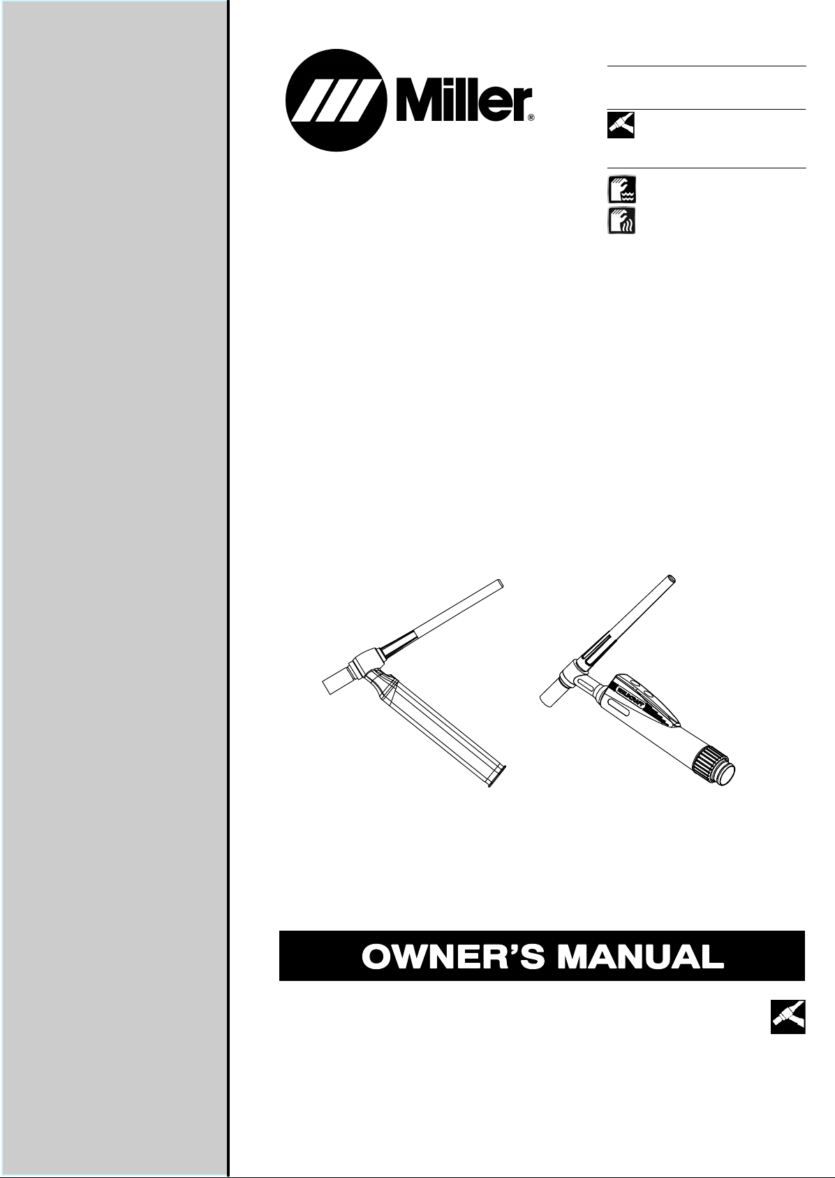
Hand-Held Water-Cooled TIG
(GTAW) Torches
Hand-Held Air-Cooled TIG
(GTAW) Torches
WP And CS Series Torches
File: TIG (GTAW)
Page 2
From Miller to You
Thank you and congratulations on choosing Miller. Now you can get the
job done and get it done right. We know you don’t have time to do it any
other way.
That’s why when Niels Miller first started building arc welders in 1929,
he made sure his products offered long-lasting value and superior quality.
Like you, his customers couldn’t afford anything less. Miller products had
to be more than the best they could be. They had to be the best you could
buy.
Today, the people that build and sell Miller products continue the
tradition. They’re just as committed to providing equipment and service
that meets the high standards of quality and value established in 1929.
This Owner’s Manual is designed to help you get the most out of your
Miller products. Please take time to read the Safety precautions. They will
help you protect yourself against potential hazards on the worksite. We’ve
made installation and operation quick and easy. With Miller you can
count on years of reliable service with proper maintenance. And if for
some reason the unit needs repair, there’s a Troubleshooting section that
will help you figure out what the problem is. The parts list will then help
you to decide which exact part you may need to fix the problem.
Warranty and service information for your particular model are also
provided.
Working as hard as you do
− every power source from
Miller is backed by the most
hassle-free warranty in the
business.
Miller Electric manufactures a full line of
welders and welding related equipment. For
information on other quality Miller products, contact your local Miller
distributor to receive the latest full line catalog or individual catalog sheets.
Page 3

TABLE OF CONTENTS
SECTION 1 −SAFETY PRECAUTIONS FOR GTAW TORCHES − READ BEFORE USING 1............
1-1. Symbol Usage 1.......................................................................
1-2. Arc Welding Hazards 1.................................................................
1-3. Proposition 65 Warnings 2...............................................................
1-4. Principal Safety Standards 2.............................................................
1-5. EMF Information 2.....................................................................
SECTION 2 −DEFINITIONS 3..................................................................
SECTION 3 − SPECIFICATIONS 4..............................................................
3-1. Specifications Table 4...................................................................
3-2. Duty Cycle 5..........................................................................
SECTION 4 − INSTALLATION 5................................................................
4-1. Required Torch Parts And Torch Assembly − CS Series Torches 5.............................
4-2. Required Torch Parts And Torch Assembly − WP Series Water-Cooled Torches 6................
4-3. Required Torch Parts And Torch Assembly − WP Series Air-Cooled Torches 6...................
4-4. Remote 6 Receptacle Information For 15 Volts DC 7.........................................
4-5. Remote 14 Receptacle Information For 15 Volts DC 7........................................
4-6. Remote 14 Receptacle Information For 24 Volts AC 7........................................
4-7. Connecting Torch 8.....................................................................
SECTION 5 − MAINTENANCE & TROUBLESHOOTING 10.........................................
5-1. Routine Maintenance 10.................................................................
5-2. Troubleshooting 10......................................................................
SECTION 6 − ELECTRICAL DIAGRAMS 11.......................................................
SECTION 7 − SELECTING AND PREPARING A TUNGSTEN FOR DC OR AC PHASE
MACHINE WELDING 12........................................................................
7-1. Selecting Tungsten Electrode (Wear Clean Gloves To Prevent Contamination Of Tungsten) 12......
7-2. Preparing Tungsten Electrode For Welding With Phase Control Machines 12.....................
SECTION 8 − GUIDELINES FOR TIG WELDING (GTAW) 13.........................................
8-1. Positioning The Torch 13.................................................................
8-2. Torch Movement During Welding 14........................................................
8-3. Positioning Torch Tungsten For Various Weld Joints 14........................................
Page 4

Page 5
SECTION 1 −SAFETY PRECAUTIONS FOR GTAW
TORCHES − READ BEFORE USING
SR6 (TIG) 2018-01
Protect yourself and others from injury — read, follow, and save these important safety precautions and operating instructions.
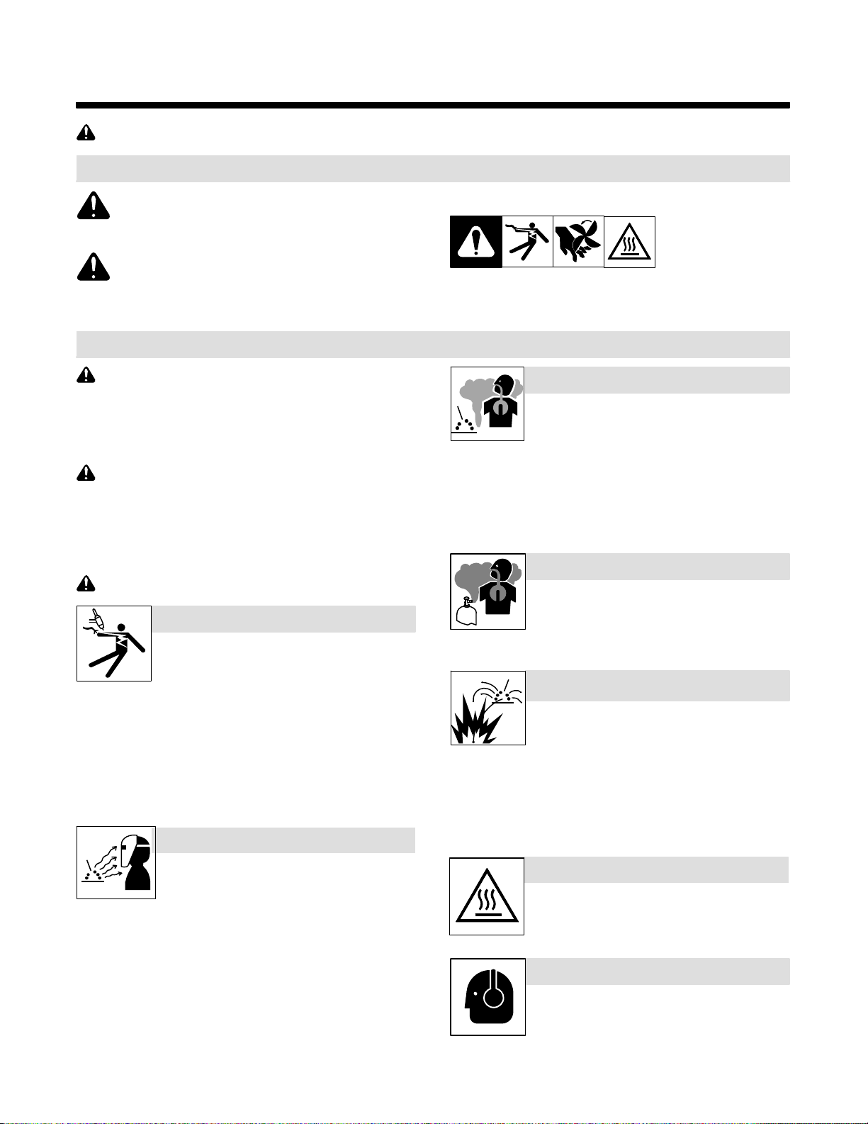
1-1. Symbol Usage
DANGER! − Indicates a hazardous situation which, if
not avoided, will result in death or serious injury. The
possible hazards are shown in the adjoining symbols
or explained in the text.
Indicates a hazardous situation which, if not avoided,
could result in death or serious injury. The possible
hazards are shown in the adjoining symbols or explained in the text.
NOTICE − Indicates statements not related to personal injury.
1-2. Arc Welding Hazards
The symbols shown below are used throughout this manual
to call attention to and identify possible hazards. When you
see the symbol, watch out, and follow the related instructions
to avoid the hazard. The safety information given below is
only a summary of the more complete safety information
found in the welding power source Owner’s Manual. Read
and follow all Safety Standards.
Only qualified persons should install, operate, maintain, and
repair this equipment. A qualified person is defined as one
who, by possession of a recognized degree, certificate, or
professional standing, or who by extensive knowledge, training and experience, has successfully demonstrated ability to
solve or resolve problems relating to the subject matter, the
work, or the project and has received safety training to recognize and avoid the hazards involved.
During operation, keep everybody, especially children, away.
ELECTRIC SHOCK can kill.
D Always wear dry insulating gloves.
D Insulate yourself from work and ground.
D Do not touch live electrode or electrical parts.
D Before welding, verify torch head is firmly attached to the torch
body.
D Do not wrap water-cooled torch hoses and power cables together
with tape or plastic wire ties. Wrapping restricts water flow which
can cause power cable to overheat and torch hose to burst.
D Replace worn, damaged, or cracked torches or cables.
D Turn off welding power source before changing tungsten elec-
trode or torch parts.
D Keep all covers and handle securely in place.
ARC RAYS can burn eyes and skin.
Arc rays from the welding process produce intense
visible and invisible (ultraviolet and infrared) rays
that can burn eyes and skin. Sparks fly off from the
weld.
D Wear an approved welding helmet fitted with a proper shade of filter
lenses to protect your face and eyes from arc rays and sparks
when welding or watching (see ANSI Z49.1 and Z87.1 listed in
Safety Standards).
D Wear approved safety glasses with side shields under your
helmet.
D Use protective screens or barriers to protect others from flash,
glare and sparks; warn others not to watch the arc.
D Wear body protection made from durable, flame-resistant material
(leather, heavy cotton, wool). Body protection includes oil-free
clothing such as leather gloves, heavy shirt, cuffless trousers, high
shoes, and a cap.
. Indicates special instructions.
This group of symbols means Warning! Watch Out! ELECTRIC
SHOCK, MOVING PARTS, and HOT PARTS hazards. Consult symbols and related instructions below for necessary actions to avoid the
hazards.
FUMES AND GASES can be hazardous.
D Keep your head out of the fumes.
D Ventilate area, or use breathing device. The
recommended way to determine adequate
ventilation is to sample for the composition and quantity of fumes
and gases to which personnel are exposed.
D Read and understand the Safety Data Sheets (SDSs) and the
manufacturer’s instructions for adhesives, coatings, cleaners,
consumables, coolants, degreasers, fluxes, and metals.
BUILDUP OF GAS can injure or kill.
D Shut off compressed gas supply when not in
use.
D Always ventilate confined spaces or use ap-
proved air-supplied respirator.
WELDING can cause fire or explosion.
D Do not weld near flammable material.
D Do not weld on containers that have held com-
bustibles, or on closed containers such as
tanks, drums, or pipes unless they are properly prepared according to AWS F4.1 and AWS A6.0 (see Safety Standards).
D Watch for fire; keep extinguisher nearby.
D Read and understand the Safety Data Sheets (SDSs) and the
manufacturer’s instructions for adhesives, coatings, cleaners,
consumables, coolants, degreasers, fluxes, and metals.
HOT PARTS can burn.
D Allow torch to cool before touching.
D Do not touch hot metal.
D Protect hot metal from contact by others.
NOISE can damage hearing.
D Check for noise level limits exceeding those spe-
cified by OSHA.
D Use approved ear plugs or ear muffs if noise level
is high.
D Warn others nearby about noise hazard.
OM-251981 Page 1
Page 6

READ INSTRUCTIONS.
D Read and follow all labels and the Owner’s
Manual carefully before installing, operating, or
servicing unit. Read the safety information at
the beginning of the manual and in each section.
1-3. Proposition 65 Warnings
WARNING: This product can expose you to chemicals including lead, which are known to the state of California to
cause cancer and birth defects or other reproductive
harm.
For more information, go to www.P65Warnings.ca.gov.
1-4. Principal Safety Standards
D Use only genuine replacement parts from the manufacturer.
D Perform installation, maintenance, and service according to the
Owner’s Manuals, industry standards, and national, state, and local codes.
Safety in Welding, Cutting, and Allied Processes, ANSI Standard Z49.1,
is available as a free download from the American Welding Society at
http://www.aws.org or purchased from Global Engineering Documents
(phone: 1-877-413-5184, website: www.global.ihs.com).
Safe Practice For Occupational And Educational Eye And Face Protection, ANSI Standard Z87.1, from American National Standards Institute,
25 West 43rd Street, New York, NY 10036 (phone: 212-642-4900, website: www.ansi.org).
Safe Practices for the Preparation of Containers and Piping for Welding
and Cutting, American Welding Society Standard AWS F4.1, from Glob-
al Engineering Documents (phone: 1-877-413-5184, website: www.global.ihs.com).
Safe Practices for Welding and Cutting Containers that have Held Combustibles, American Welding Society Standard AWS A6.0, from Global
Engineering Documents (phone: 1-877-413-5184,
website: www.global.ihs.com).
National Electrical Code, NFPA Standard 70, from National Fire Protection Association, Quincy, MA 02169 (phone: 1-800-344-3555, website:
www.nfpa.org and www. sparky.org).
1-5. EMF Information
Electric current flowing through any conductor causes localized electric
and magnetic fields (EMF).The current from arc welding (and allied processes including spot welding, gouging, plasma arc cutting, and induction heating operations) creates an EMF field around the welding circuit.
EMF fields can interfere with some medical implants, e.g. pacemakers.
Protective measures for persons wearing medical implants have to be
taken. For example, restrict access for passers−by or conduct individu-
al risk assessment for welders. All welders should use the following procedures in order to minimize exposure to EMF fields from the welding
circuit:
1. Keep cables close together by twisting or taping them, or using a
cable cover.
2. Do not place your body between welding cables. Arrange cables
to one side and away from the operator.
3. Do not coil or drape cables around your body.
Safe Handling of Compressed Gases in Cylinders, CGA Pamphlet P-1,
from Compressed Gas Association, 14501 George Carter Way, Suite
103, Chantilly, VA 20151 (phone: 703-788-2700, website:
www.cganet.com).
Safety in Welding, Cutting, and Allied Processes, CSA Standard
W117.2, from Canadian Standards Association, Standards Sales, 5060
Spectrum Way, Suite 100, Mississauga, Ontario, Canada L4W 5NS
(phone: 800-463-6727, website: www.csagroup.org).
Safe Practice For Occupational And Educational Eye And Face Protection, ANSI Standard Z87.1, from American National Standards Institute,
25 West 43rd Street, New York, NY 10036 (phone: 212-642-4900, website: www.ansi.org).
Standard for Fire Prevention During Welding, Cutting, and Other Hot
Work, NFPA Standard 51B, from National Fire Protection Association,
Quincy, MA 02169 (phone: 1-800-344-3555, website: www.nfpa.org).
OSHA, Occupational Safety and Health Standards for General Indus-
try, Title 29, Code of Federal Regulations (CFR), Part 1910.177 Subpart
N, Part 1910 Subpart Q, and Part 1926, Subpart J, from U.S. Government Printing Office, Superintendent of Documents, P.O. Box 371954,
Pittsburgh, PA 15250-7954 (phone: 1-866-512-1800) (there are 10 OSHA Regional Offices—phone for Region 5, Chicago, is 312-353-2220,
website: www.osha.gov).
4. Keep head and trunk as far away from the equipment in the
welding circuit as possible.
5. Connect work clamp to workpiece as close to the weld as
possible.
6. Do not work next to, sit or lean on the welding power source.
7. Do not weld whilst carrying the welding power source or wire
feeder.
About Implanted Medical Devices:
Implanted Medical Device wearers should consult their doctor and the
device manufacturer before performing or going near arc welding, spot
welding, gouging, plasma arc cutting, or induction heating operations.
If cleared by your doctor, then following the above procedures is recommended.
OM-251981 Page 2
Page 7
Notes
SECTION 2 −DEFINITIONS
Warning! Watch Out! There are possible hazards as shown by the symbols.
Safe1 2012−05
Do not discard product (where applicable) with general waste.
Reuse or recycle Waste Electrical and Electronic Equipment (WEEE) by disposing at a designated collection
facility.
Contact your local recycling office or your local distributor for further information.
Safe37 2017−04
OM-251981 Page 3
Page 8

SECTION 3 − SPECIFICATIONS
3-1. Specifications Table
WP-27BHD Liquid 12.5/3.8, 25/7.6 900 630 100 1.0-6.4 15 40 1 3.5
WP-27 A/B Liquid 12.5/3.8, 25/7.6 500 350 100 1.0-6.4 15 40 1 3.5
CS310A Liquid 12.5/3.8, 25/7.6 310 220 100 0.5-3.2 15 40 1 3.5 4.5 1.6
CS410A Liquid 12.5/3.8, 25/7.6 410 290 100 0.5-4.0 15 40 1 3.5 4.5 1.6
WP-375 Liquid 12.5/3.8, 25/7.6 375 265 100 0.5-3.2 15 40 1 3.5 4.5 2.6
WP-280 Liquid 12.5/3.8, 25/7.6 280 195 100 0.5-3.2 15 40 1 3.5 4.5 2.6
WP-225 Liquid 12.5/3.8, 25/7.6 225 160 100 0.5-4.0 15 40 1 3.5 4.5 1.4
(*L,M)
Liquid 12.5/3.8, 25/7.6 125 90 100 1.0-2.4 15 40 1 3.5 4.5 1.4
WP-125
WP-25 Liquid 12.5/3.8, 25/7.6 200 140 100 0.5-3.2 15 40 1 3.5 4.5 1.0
WP-24W Liquid 12.5/3.8, 25/7.6 180 125 100 0.5-2.4 15 40 1 3.5 4.5
WP-22A Liquid 12.5/3.8, 25/7.6 250 175 100 1.0-3.2 15 40 1 3.5 4.5
WP-20P Liquid 12.5/3.8, 25/7.6 225 160 100 0.5-3.2 15 40 1 3.5 4.5
WP-20 (*V) Liquid 12.5/3.8, 25/7.6 250 175 100 1.0-3.2 15 40 1 3.5 4.5 1.6
WP-18P Liquid 12.5/3.8, 25/7.6 500 350 100 0.5-4.0 15 40 1 3.5 4.5
WP-18SC Liquid 12.5/3.8, 25/7.6 400 280 100 0.5-4.8 15 40 1 3.5 4.5 1.6
WP-18 (*V) Liquid 12.5/3.8, 25/7.6 350 245 100 0.5-4.0 15 40 1 3.5 4.5 1.6
WP-12 Liquid 12.5/3.8, 25/7.6 500 350 100 1.6-6.4 15 40 1 3.5 4.5
WP-150 (*V) Air 12.5/3.8, 25/7.6 150 105 60 0.5-3.2 15 −− −− −− −− −−
WP-200 (*V) Air 12.5/3.8, 25/7.6 200 140 60 0.5-4.0 15 −− −− −− −− −−
(*F,V,FV)
(*F,FV)
WP-26
Air 12.5/3.8, 25/7.6 80 55 100 0.5-2.4 15 −− −− −− −− −−
Air 12.5/3.8, 25/7.6 200 140 60 0.5-4.0 15 −− −− −− −− −−
(*F,V,FV)
WP-23A Air 12.5/3.8, 25/7.6 150 105 60 1.0-2.4 15 −− −− −− −− −−
WP-24
WP-17
Air 12.5/3.8, 25/7.6 150 105 35 0.5-3.2 15 −− −− −− −− −−
(*F,V,FV,P)
WP-9
Air 12.5/3.8, 25/7.6 125 90 60 0.5-3.2 15 −− −− −− −− −−
*Includes
Model
Cooling
Type
Lengths
Ft/m Amps Amps % mm Kv 5C L/min Bar Bar kW
Torch
DC AC
Load
(Argon)
Cycle
Duty
Tungsten
Diameter
Striking
Voltage
Arc
Max. Supply
Temp.
Flow
Min.
Min. Inlet
Pressure
Cooling
OM-251981 Page 4
4.5 2.6
4.5 2.6
1.4
1.4
1.0
1.6
2.6
Max. Inlet
Pressure
Min. Cooling
Power
Page 9
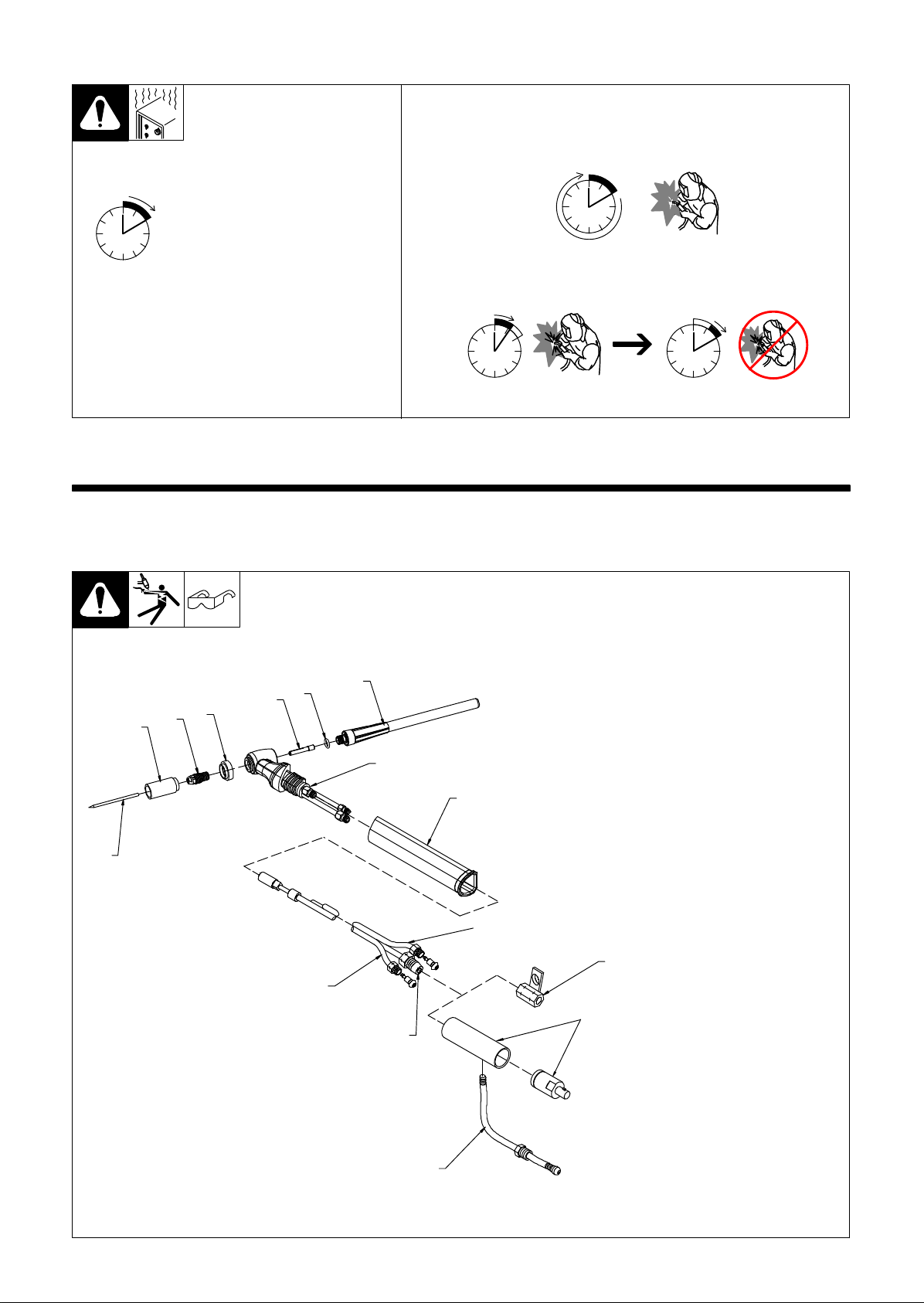
3-2. Duty Cycle
NOTICE − Do not exceed rated amperage or duty cycle (see Section 3-1). Ex-
ceeding rated amperage or duty cycle can damage torch and void warranty.
100% Duty Cycle
Continuous Welding
60% Duty Cycle
0
Minutes
10
Examples:
Definition:
Duty Cycle is percentage of 10
minutes that torch can weld at
rated load without overheating.
6 Minutes Welding 4 Minutes Resting
SECTION 4 − INSTALLATION
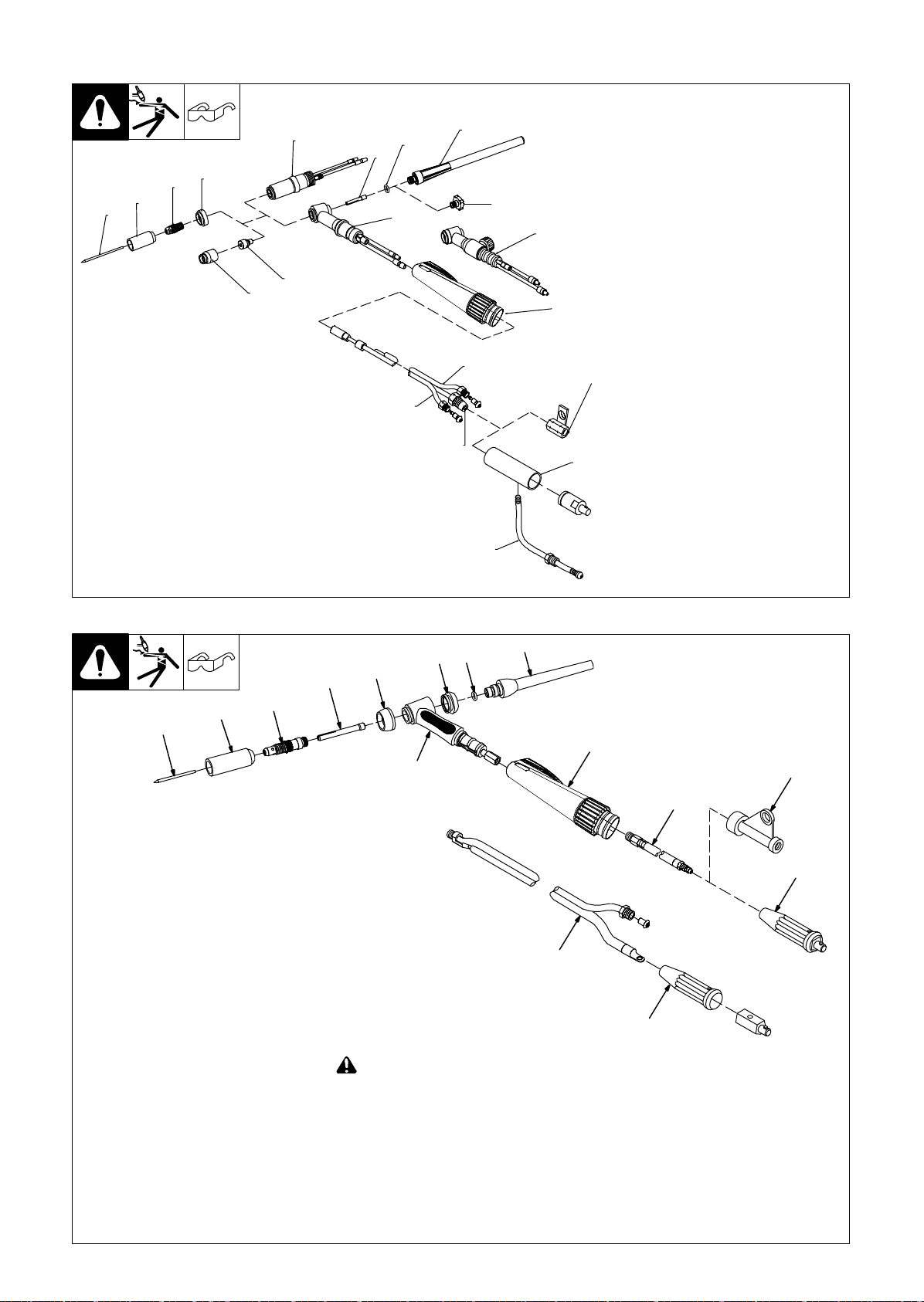
4-1. Required Torch Parts And Torch Assembly − CS Series Torches
1 Cup
2 Collet Body
3 Heat Shield
4 Collet
5 O-Ring
6 Backcap
7 Torch Body
8 Handle
9 Power Cable
10 Water Hose
11 Gas Hose
12 Power Cable Adapter
13 International Style Adapter
14 Water Hose For International
Assembling Torch Body
Keep connections tight. Replace
cup, heat shield, and backcap as
needed.
15 Tungsten Electrode (See Sec-
12
Installing Tungsten
To adjust tungsten position, loosen
backcap.
15
Assembling Torch Parts
5
3
2
1
4
6
7
8
11
10
13
9
Style Adapter
tion 7)
14
804302-A
OM-251981 Page 5
Page 10
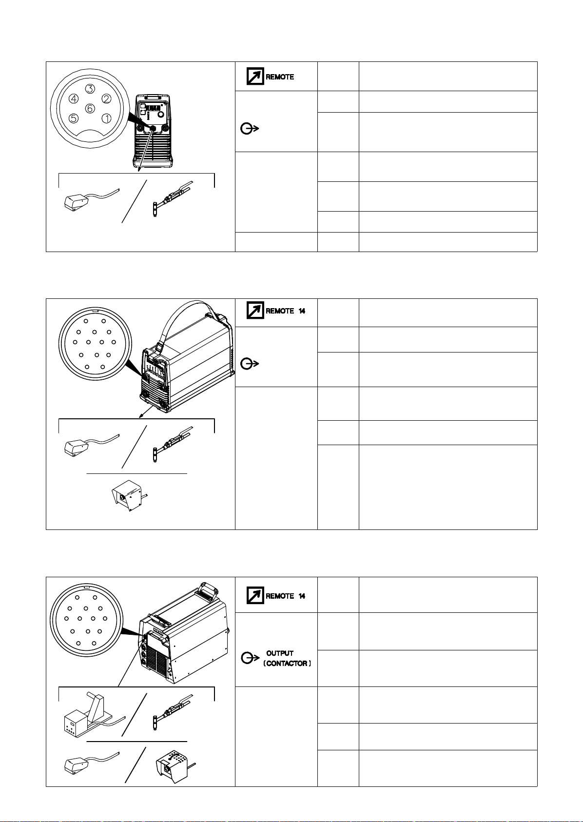
4-2. Required Torch Parts And Torch Assembly − WP Series Water-Cooled Torches
17
Assembling Torch Parts
4A
5
6
7
8
9
2
3
4
12
1
1
4B
10
13
11
15
16
1 Backcap
2 O-Ring
3 Collet
4 Torch Body (Standard)
4A Torch Body (Pencil)
4B Torch Body (w/Gas Valve)
5 Heat Shield
6 Collet Body
7 Cup
8 Gas Lens
9 Gas Lens Nozzle
10 Handle
11 Power Cable
12 Water Hose
14
13 Gas Hose
14 Power Cable Adapter
15 International Style Adapter
16 Water Hose For International Style
Adapter
Assembling Torch Body
Keep connections tight. Replace cup,
heat shield, and backcap as needed.
17 Tungsten Electrode (See Section 7)
Installing Tungsten
To adjust tungsten position, loosen backcap.
804308-B
4-3. Required Torch Parts And Torch Assembly − WP Series Air-Cooled Torches
7
9
10
Or
13
14
15
3
1
2
Assembling Torch Parts
6
4
5
8
11
12
804305-A
1 Cup
2 Collet Body
3 Collet
4 Heat Shield
5 Backcap Insulator
6 O-Ring
7 Backcap
8 Torch Body/Torch Head
OM-251981 Page 6
! Before welding, insure that the torch
head is firmly attached to the torch
body.
9 Handle
10 One-Piece Power Cable
11 Power Cable Adapter
12 International Style Flow-Through
Adapter
. The adapter is needed only if torch is
equipped with one-piece cable.
13 Two-Piece Power Cable
14 International Style Connector
. The connector is needed only if torch is
equipped with two-piece cable (see
Section 4-7B).
Assembling Torch Body
Keep connections tight. Replace cup, heat
shield, and backcap as needed.
15 Tungsten Electrode (See Section 7)
Installing Tungsten
To adjust tungsten position, loosen
backcap.
Page 11
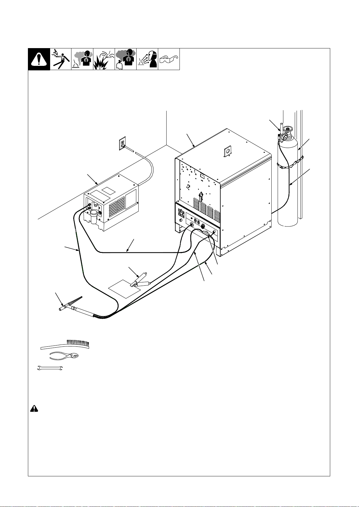
4-4. Remote 6 Receptacle Information For 15 Volts DC
Socket Socket Information
6
1 Contactor control +15 volts DC.
15 VOLTS DC
OUTPUT
CONTACTOR
REMOTE
OUTPUT
CONTROL
2 Contact closure to 1 completes contactor control
3 Output to remote control; +10 volts DC output to
4 0 to +10 volts DC input command signal from
circuit and enables output when Lift-Arc TIG remote is selected.
remote control.
remote control.
Ref. 805575-A
CHASSIS
5 Remote control circuit common.
6 Chassis common.
4-5. Remote 14 Receptacle Information For 15 Volts DC
Socket Socket Information
AJ
K
B
L
C
D
I
NH
M
G
F
E
805497-A
15 VOLTS DC
OUTPUT
CONTACTOR
REMOTE
OUTPUT
CONTROL
A Contactor control +15 volts DC, referenced to G.
B Contact closure to A completes 15 volts DC
C Output to remote control; +10 volts DC output to
D Remote control circuit common.
E 0 to +10 volts DC input command signal from
contactor control circuit and enables output.
remote control.
remote control.
*Reconfigurable as input for Output Enable (Weld
Stop) − used to remotely stop the weld outside the
normal welding cycle. Connection to the D socket
must be maintained at all times. If the connection
is broken, output stops, and Auto Stop is displayed.
4-6. Remote 14 Receptacle Information For 24 Volts AC
AJ
K
B
L
NH
C
M
D
F
E
I
G
24 VOLTS AC
REMOTE
OUTPUT
CONTROL
Socket Socket Information
A 24 volts AC. Protected by supplementary protect-
B Contact closure to A completes 24 volts AC
C Output to remote control; 0 to +10 volts DC, +10
D Remote control circuit common.
E 0 to +10 volts DC input command signal from
or CB2.
contactor control circuit.
volts DC in MIG mode.
remote control.
OM-251981 Page 7
Page 12
4-7. Connecting Torch
A. Connecting Water-Cooled Torch When Using A Freestanding Coolant System
1
2
3
10
5
Tools Needed:
11
7
12
6
8
9
4
5/8, 7/8, 1-1/8 in.
! Turn Off welding power source and
cooling system power before installing torch.
. If applicable, install high-frequency
unit.
1 Welding Power Source
2 Regulator/Flowmeter
3 Gas Cylinder
4 Gas Hose (Customer Supplied)
OM-251981 Page 8
Obtain correct length with 5/8-18 right-hand
fittings.
5 Torch
6 Power Cable Adapter
7 Coolant Hose (Customer Supplied)
Obtain correct length with 5/8-18 left-hand
fittings.
8 Coolant-Out Of Torch/Power Cable
(Red)
802560
Connect coolant-out of torch/power cable
to power cable adapter, and connect adapter to weld output terminal.
9 Torch Gas Hose
10 Coolant-Into Torch Hose (Blue)
11 Cooling System
12 Work Clamp
Connect work clamp to a clean, paint-free
location on workpiece, close to the weld.
Use wire brush or sandpaper to clean weld
joint area.
Page 13
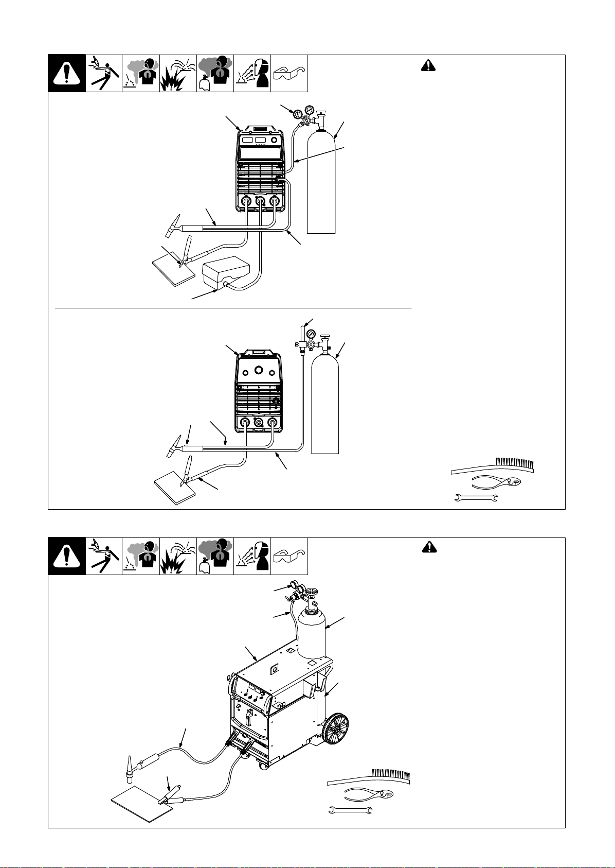
B. Connecting Air-Cooled Torch With Two-Piece Cable
2
Torch Without Gas Valve
7
8
Torch With Gas Valve
4
6
5
4
6
9
−
! Turn Off welding power source
power before installing torch.
. If applicable, install high-frequen-
cy unit.
3
1
803314
2
3
Obtain the following hose:
1 Gas Hose With 5/8-18 Right-
Hand Fittings
Connections:
2 Regulator/Flowmeter
3 Gas Cylinder
4 Welding Power Source
5 Torch Gas-In Hose
6 Torch Power Cable
7 Work Clamp
Connect work clamp to a clean, paintfree location on workpiece, close to
weld area.
Use wire brush to clean weld joint
area.
8 Foot Control
9 Gas Valve
Valve controls gas preflow and postflow. Open valve on torch just before
welding.
Preflow is used to purge the immediate weld area of atmosphere.
Postflow is required to cool tungsten
and weld, and to prevent contamination of tungsten and weld. After welding, leave valve open about 1 second
for every 10 amperes of weld current.
Close valve on torch when postflow is
finished.
Tools Needed:
5
7
803664-A
C. Connecting Air-Cooled Torch With Flow-Through Type Connection
2
3
5
Tools Needed:
Torch Without Gas Valve
6
7
1
4
5/8, 7/8 in.
! Turn Off welding power source
power before installing torch.
. If applicable, install high-frequen-
cy unit.
Obtain the following hose:
1 Gas Hose With 5/8-18 Right-
Hand Fittings
Connections:
2 Regulator/Flowmeter
3 Gas Cylinder
4 Welding Power Source
5 Gas Valve
Located on back of machine.
6 One-Piece Torch Cable
7 Work Clamp
Connect work clamp to clean, paintfree location on workpiece, close to
weld area.
Use wire brush to clean metal at weld
joint area.
5/8, 7/8 in.
804330-A
OM-251981 Page 9
Page 14
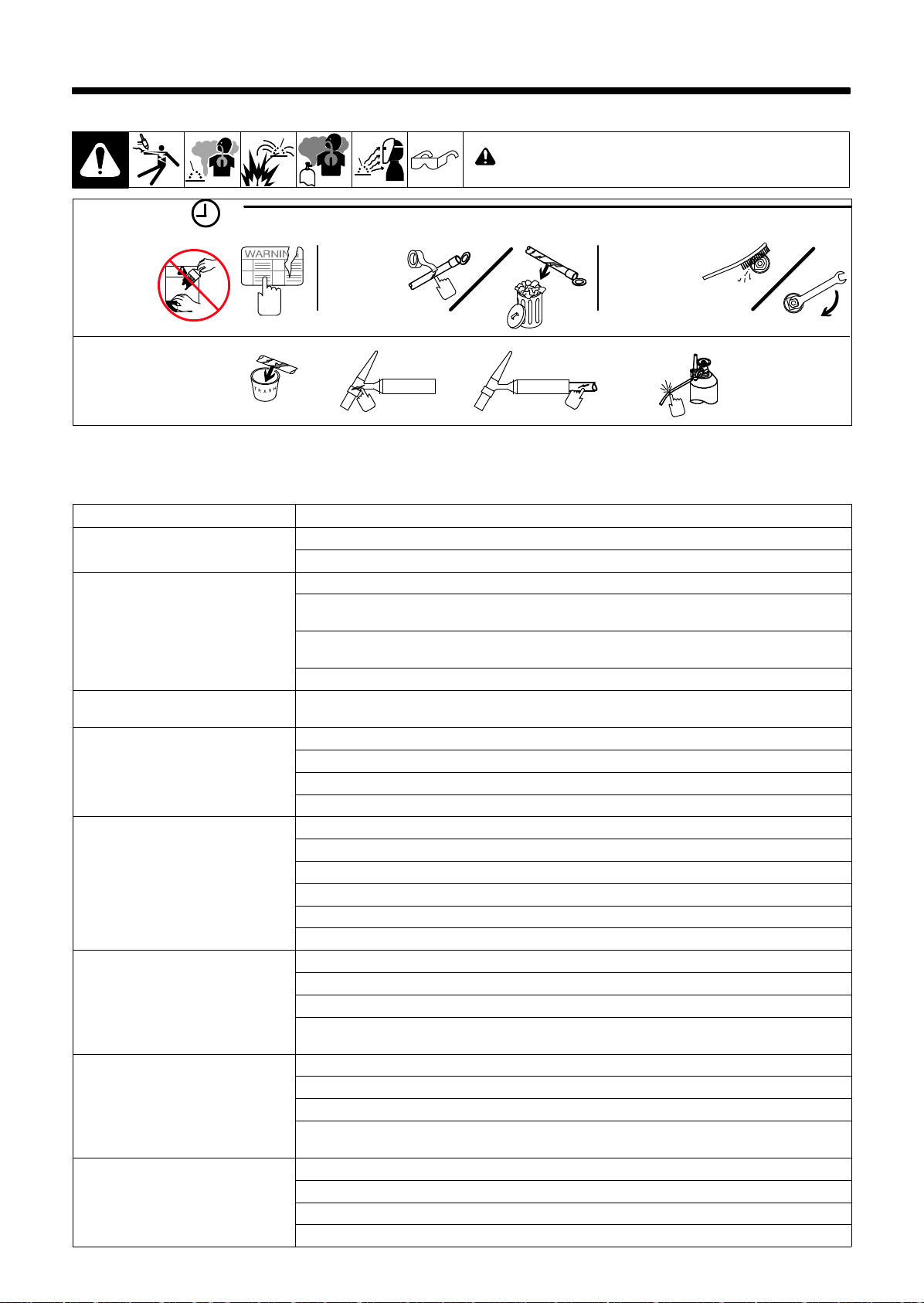
SECTION 5 − MAINTENANCE & TROUBLESHOOTING
5-1. Routine Maintenance
! Disconnect torch before maintaining.
40 Hours
Replace
unreadable
labels.
Replace cracked parts
Repair or
replace
cracked
weld cable.
Torch Body
Torch Cable
Clean and
tighten weld
terminals.
5-2. Troubleshooting
. Before using troubleshooting table, check selection and preparation of tungsten electrode according to Section 7.
Trouble Remedy
Arc will not start. High frequency present
and visible at the torch.
Lack of high frequency; difficulty in establishing arc.
Torch gas valve not working properly (if
applicable).
No shielding gas flow from torch. Be sure valves on gas supply are open.
Tungsten electrode oxidizing and not remaining bright after conclusion of weld.
Excessive tungsten electrode consumption.
Wandering arc Shield weld zone from drafts.
Yellow powder or smoke on cup. Use proper type shielding gas.
Check cable and work connections. Be sure weld circuit is complete (see Section 4-7).
Check and be sure shielding gas is present.
Select proper size and type tungsten. Properly prepare tungsten according to Section 7.
Check cables and torch for cracks or bad connections. Be sure that torch cables are not close to any
grounded metal. Repair or replace necessary parts.
Check torch consumables. Be sure collet and collet body are correctly installed and tightened (see Section 4-2).
Check welding power source High Frequency control, and if necessary, check and adjust spark gaps.
Have Factory Authorized Service Station/Service Distributor check valve.
Check cable for kinks or blockage.
Check and tighten all gas supply fittings.
Check cables and torch for cracked insulation or bad connections. Repair or replace (see Section 5-1).
Shield weld zone from drafts.
Increase postflow time.
Increase gas flow rate. Check manufacture’s recommendations.
Check and tighten all gas fittings.
Check gas valve and flow meter/regulator.
Select proper size and type tungsten. Properly prepare tungsten (see Section 7).
Select proper size and type tungsten. Properly prepare tungsten according to Section 7.
Check polarity setting on welding power source (see welding power source Owner’s manual).
Check for proper gas flow rate. Check manufacture’s recommendations.
If torch is water cooled, check torch and cables for water leaks. Repair or replace if necessary (see Section 5-1).
Reduce gas flow rate.
Select proper size and type tungsten. Properly prepare tungsten according to Section 7.
When using AC, check welding power source High Frequency control setting, and increase setting if
necessary.
Check for proper gas flow rate. Check manufacture’s recommendations.
Increase postflow time.
Check torch cup size. Match cup size to joint being welded.
OM-251981 Page 10
Page 15
Trouble Remedy
Erratic arc When using DC, check polarity, and/or polarity of welding cables.
When using AC, check welding power source High Frequency control setting, and be sure it is operating
continuously.
Select proper size and type tungsten. Properly prepare tungsten according to Section 7.
Use proper arc length. Arc length may be too long or too short.
Make sure base material is clean and free of contaminates.
When using AC, slow travel speed can cause erratic arc. Adjust travel speed.
Porosity in weld. Check for proper gas flow rate. Check manufacture’s recommendations.
Check and tighten gas fittings.
Make sure base material and filler material is clean and free of contaminates.
Check for impurities and moisture in gas lines. Purge if necessary.
If torch is water cooled, check torch and cables for water leaks. Repair or replace if necessary (see Section 5-1).
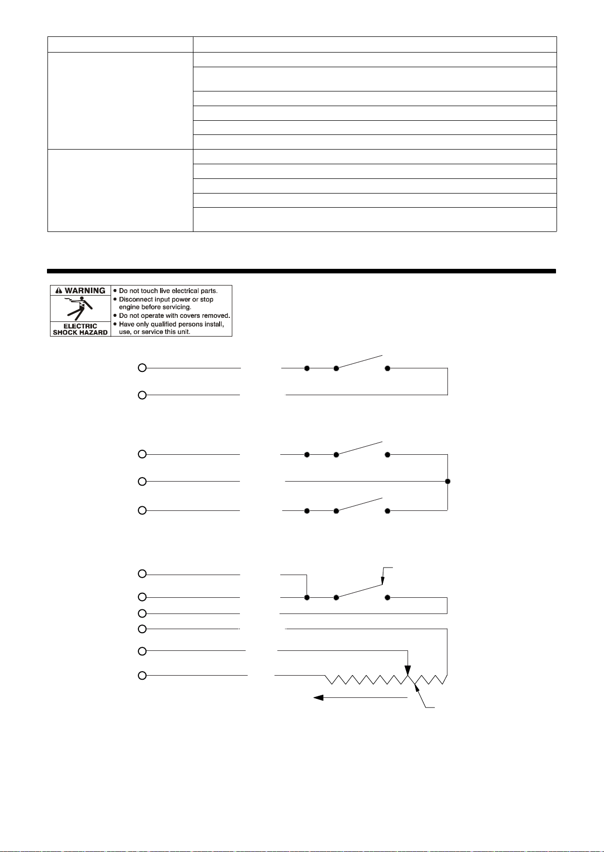
SECTION 6 − ELECTRICAL DIAGRAMS
BROWN
GREEN
Torches With Single Trigger
GREEN
WHITE
BROWN
Torches With Double Trigger
GREEN
BROWN
WHITE
YELLOW
GREY
MAINTAINED (LATCHING) SWITCH
PINK
INCREASE
Torches With Trigger And Potentiometer
POTENTIOMETER
OM-251981 Page 11
Page 16
SECTION 7 − SELECTING AND PREPARING A TUNGSTEN
FOR DC OR AC PHASE MACHINE WELDING
Ref. gtaw_Phase_2018−01
! Whenever possible and practical, use DC weld output instead of AC weld output.
7-1. Selecting Tungsten Electrode (Wear Clean Gloves To Prevent Contamination Of Tungsten)
A. Select Tungsten Electrode
. Not all tungsten electrode manufacturers use the same colors to identify tungsten type. Contact the tungsten electrode manufacturer or refer-
ence the product packaging to identify the tungsten you are using.
Amperage Range - Gas Type♦ - Polarity
Electrode Diameter (DCEN) − Argon
Direct Current Electrode Negative
(For Use With Mild Or Stainless Steel)
2% Ceria Or 1.5% Lanthanum
.040” (1 mm) 15-80 15-80
1/16” (1.6 mm) 70-150 70-150
3/32” (2.4 mm) 150-250 140-235
1/8” (3.2 mm) 250-400 225-325
Pure Tungsten
.040” (1 mm) Pure Tungsten Not Recommended
1/16” (1.6 mm) 50-100
3/32” (2.4 mm) 100-160
1/8” (3.2 mm) 150-210
For DCEN − Argon
AC − Argon
Unbalanced Wave
(For Use With Aluminum)
10-60
♦Typical argon shielding gas flow rates are 10 to 25 CFH (cubic feet per hour).
Figures listed are a guide and are a composite of recommendations from American Welding Society (AWS).
7-2. Preparing Tungsten Electrode For Welding With Phase Control Machines
! Grinding the tungsten electrode produces dust and flying sparks which can cause injury and start fires. Use
local exhaust (forced ventilation) at the grinder or wear an approved respirator. Read MSDS for safety information. Consider using tungsten containing ceria, lanthana, or yttria instead of thoria. Grinding dust from
thoriated electrodes contains low-level radioactive material. Properly dispose of grinder dust in an environmentally safe way. Wear proper face, hand, and body protection. Keep flammables away.
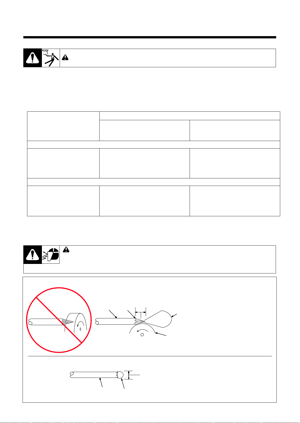
A. Preparing Tungsten For DC Electrode Negative (DCEN) Welding
Radial Grinding
Causes Wandering Arc
2
1-1/2 To 4 Times
Electrode Diameter
4
3
15° to 30°
1 Grinding Wheel
Grind end of tungsten on fine grit, hard
abrasive wheel before welding. Do not use
wheel for other jobs or tungsten can become
contaminated causing lower weld quality.
2 Tungsten Electrode
A 2% ceriated tungsten is recommended.
3 Ideal Grind Angle Range: 15° to 30°
. 30 degrees is the recommended elec-
Wrong Tungsten Preparation
Ideal Tungsten Preparation − Stable Arc
B. Preparing Tungsten For AC Welding
1
1 − 1-1/2 Times
Electrode Diameter
2
1
trode grind angle.
4 Straight Ground
Grind lengthwise, not radial.
1 Tungsten Electrode
A pure tungsten is recommended..
2 Balled End
Ball end of tungsten by applying AC amperage recommended for a given electrode
diameter (see Section 7-1). Let ball on end of
the tungsten take its own shape.
OM-251981 Page 12
Page 17
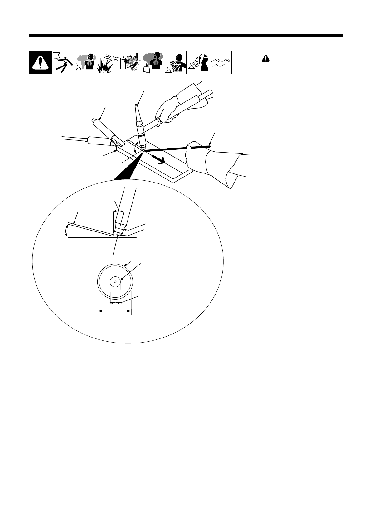
SECTION 8 − GUIDELINES FOR TIG WELDING (GTAW)
8-1. Positioning The Torch
! Grinding the tungsten elec-
trode produces dust and flying sparks which can cause
injury and start fires. Use local exhaust (forced ventilation) at the grinder or wear an
approved respirator. Read
MSDS for safety information.
Consider using cerium or
lanthanum based tungsten
instead of thoriated. Thorium dust contains low-level
radioactive material. Properly dispose of grinder dust in
an environmentally safe way.
Wear proper face, hand, and
body protection. Keep flammables away.
1 Workpiece
Make sure workpiece is clean
before welding.
2 Work Clamp
Place as close to the weld as
possible.
3 Torch
4 Filler Rod (If Applicable)
5 Gas Cup
6 Tungsten Electrode
Select and prepare tungsten
according to Section 7.
Guidelines:
The inside diameter of the gas cup
should be at least three times the
tungsten diameter to provide adequate shielding gas coverage. (For
example, if tungsten is 1/16 in
diameter, gas cup should be a
minimum of 3/16 in diameter.
Tungsten extension is the distance
the tungsten extends out gas cup of
torch.
The tungsten extension should be
no greater than the inside diameter
of the gas cup.
Arc length is the distance from the
tungsten to the workpiece.
10−25°
2
1
10−15°
4
3/16 in
Bottom View Of Gas Cup
90°
5
3
4
5
6
6
1/16 in
Ref.161892
OM-251981 Page 13
Page 18
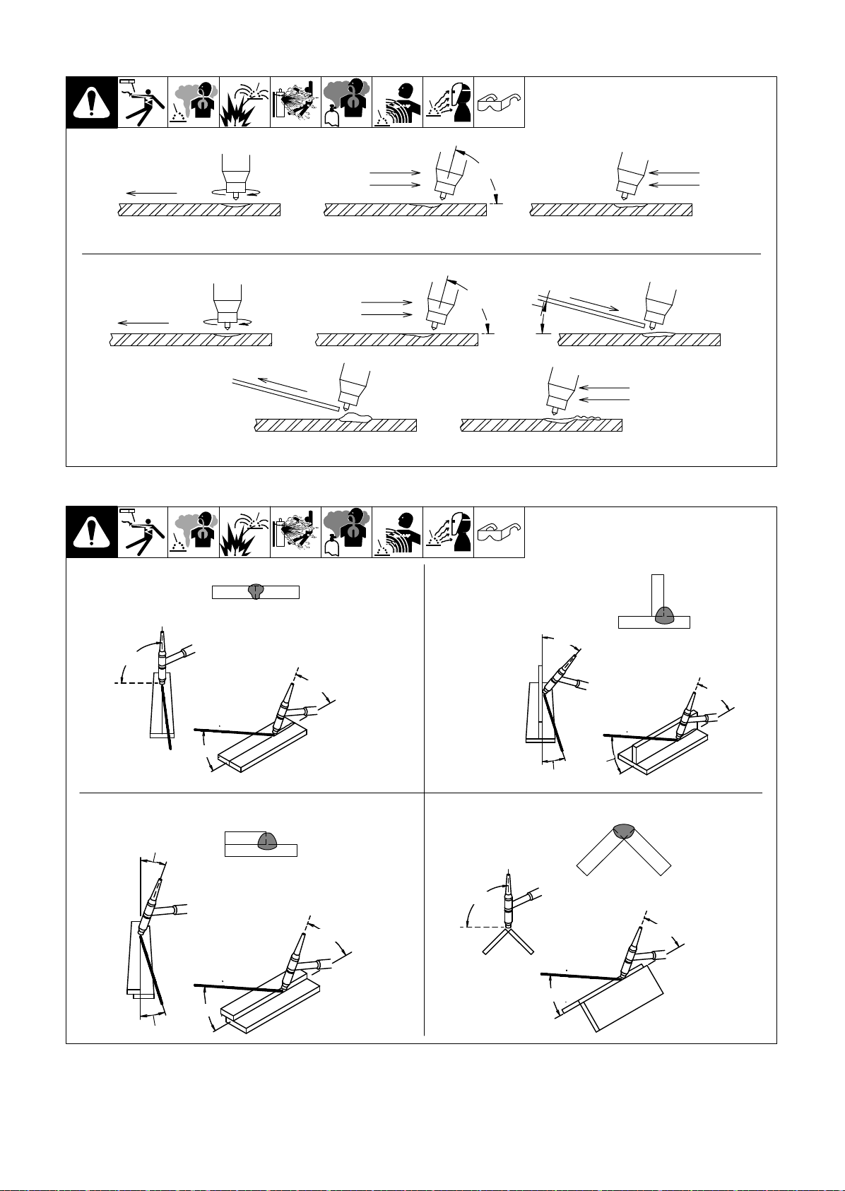
8-2. Torch Movement During Welding
Tungsten Without Filler Rod
Welding direction
Form pool Tilt torch Move torch to front
Tungsten With Filler Rod
Welding direction
Form pool Tilt torch Add filler metal
Remove rod
75°
75°
15°
Move torch to front
of pool. Repeat process.
8-3. Positioning Torch Tungsten For Various Weld Joints
Butt Weld And Stringer Bead
of pool. Repeat process.
162002-B
“T” Joint
90°
20-40°
30°
20°
15°
Lap Joint
70°
75°
20°
75°
15°
10°
Corner Joint
90°
75°
15°
162003 / 0792
OM-251981 Page 14
Page 19
Effective January 1, 2018
(Equipment with a serial number preface of MJ or newer)
This limited warranty supersedes all previous Miller warranties and is exclusive with no other
LIMITED WARRANTY − Subject to the terms and conditions
below, ITW Welding Products Italy warrants to its original retail
purchaser that new Miller equipment sold after the effective date
of this limited warranty is free of defects in material and
workmanship at the time it is shipped by Miller. THIS
WARRANTY IS EXPRESSLY IN LIEU OF ALL OTHER
WARRANTIES, EXPRESS OR IMPLIED, INCLUDING THE
WARRANTIES OF MERCHANTABILITY AND FITNESS.
Within the warranty periods listed below, Miller will repair or
replace any warranted parts or components that fail due to such
defects in material or workmanship. Miller must be notified in
writing within thirty (30) days of such defect or failure, at which
time Miller will provide instructions on the warranty claim
procedures to be followed. If notification is submitted as an
online warranty claim, the claim must include a detailed
description of the fault and the troubleshooting steps taken to
identify failed components and the cause of their failure.
Miller shall honor warranty claims on warranted equipment listed
below in the event of such a failure within the warranty time
periods. All warranty time periods start on the date the
equipment was delivered to the original retail purchaser or one
year after the equipment is shipped to a European distributor or
twelve months after the equipment is shipped to an International
distributor.
1. 5 Years Parts — 3 Years Labor
* Original main power rectifiers only to include SCRs,
diodes, and discrete rectifier modules with
exclusion of STR, Si, STi, STH and MPi series.
2. 3 Years — Parts and Labor
* Engine Driven Welding Generators
(NOTE: Engines are warranted separately by the
engine manufacturer.)
* Inverter Power Sources (Unless Otherwise Stated)
* Process Controllers
* Semi-Automatic and Automatic Wire Feeders
* Transformer/Rectifier Power Sources
3. 2 Years — Parts
* Auto-Darkening Helmet Lenses (No Labor)
* Migmatic 175
* HF Units
4. 1 Year — Parts and Labor Unless Specified
* Automatic Motion Devices
* Field Options
(NOTE: Field options are covered under True
Blue) for the remaining warranty period of the
product they are installed in, or for a minimum of
one year — whichever is greater.)
* Induction Heating Power Sources, Coolers, and
Electronic Controls/Recorders
* Motor-Driven Guns (w/exception of Spoolmate
Spoolguns)
* Positioners and Controllers
* Powered Air Purifying Respirator (PAPR) Blower
Unit (No Labor)
* Racks
* Running Gear and Trailers
* Subarc Wire Drive Assemblies
* Water Cooling Systems
* Work Stations/Weld Tables (No Labor)
5. 6 Months — Parts
* Batteries
guarantees or warranties expressed or implied.
6. 90 Days — Parts
* Accessory (Kits)
* Canvas Covers
* Induction Heating Coils and Blankets
* MIG Guns
* Remote Controls
* Replacement Parts (No Labor)
* Spoolmate Spoolguns
* Cables and Non-Electronic Controls
Miller’s True Blue® Limited Warranty shall not apply to:
1. Consumable components; such as contact tips,
cutting nozzles, contactors, brushes, switches, slip
rings, relays or parts that fail due to normal wear.
2. Items furnished by Miller, but manufactured by others, such
as engines or trade accessories. These items are covered
by the manufacturer’s warranty, if any.
3. Equipment that has been modified by any party other than
Miller, or equipment that has been improperly installed,
improperly operated or misused based upon industry
standards, or equipment which has not had reasonable and
necessary maintenance, or equipment which has been
used for operation outside of the specifications for the
equipment.
MILLER PRODUCTS ARE INTENDED FOR COMMERCIAL AND
INDUSTRIAL USERS TRAINED AND EXPERIENCED IN THE
USE AND MAINTENANCE OF WELDING EQUIPMENT.
The exclusive remedies for warranty claims are, at Miller’s
option, either: (1) repair; or (2) replacement; or, if approved in
writing by Miller, (3) the pre-approved cost of repair or
replacement at an authorized Miller service station; or (4)
payment of or credit for the purchase price (less reasonable
depreciation based upon use). Products may not be returned
without Miller’s written approval. Return shipment shall be at
customer’s risk and expense.
The above remedies are F.O.B., Factory at ITW Welding
Products Group Europe or Miller’s authorized service facility.
Transportation and freight are the customer’s responsibility. TO
THE EXTENT PERMITTED BY LAW, THE REMEDIES HEREIN
ARE THE SOLE AND EXCLUSIVE REMEDIES REGARDLESS
OF THE LEGAL THEORY. IN NO EVENT SHALL MILLER BE
LIABLE FOR DIRECT, INDIRECT, SPECIAL, INCIDENTAL OR
CONSEQUENTIAL DAMAGES (INCLUDING LOSS OF
PROFIT) REGARDLESS OF THE LEGAL THEORY. ANY
WARRANTY NOT PROVIDED HEREIN AND ANY IMPLIED
WARRANTY, GUARANTY, OR REPRESENTATION,
INCLUDING ANY IMPLIED WARRANTY OF
MERCHANTABILITY OR FITNESS FOR PARTICULAR
PURPOSE, ARE EXCLUDED AND DISCLAIMED BY MILLER.
milan_warr 2018-01
Page 20
Owner’s Record
Please complete and retain with your personal records.
Model Name Serial/Style Number
Purchase Date (Date which equipment was delivered to original customer.)
Distributor
Address
City
State Zip
For Service
Contact a DISTRIBUTOR or SERVICE AGENCY near you.
Always provide Model Name and Serial/Style Number.
Contact your Distributor for: Welding Supplies and Consumables
Options and Accessories
Service and Repair
Replacement Parts
Owner’s Manuals
ITW Welding Products BV
Edisonstraat 10
3260 BB Oud−Beijerland,
Netherlands
Phone: +31186641444
Email: info@itw−welding.com
Web: www.ITWwelding.com
Contact the Delivering Carrier to:
ORIGINAL INSTRUCTIONS − PRINTED IN USA © 2018 Miller Electric Mfg. LLC 2018−01
File a claim for loss or damage during
shipment.
For assistance in filing or settling claims, contact
your distributor and/or equipment manufacturer’s
Transportation Department.
 Loading...