

Page 1
OM-255503B
2018−12
®
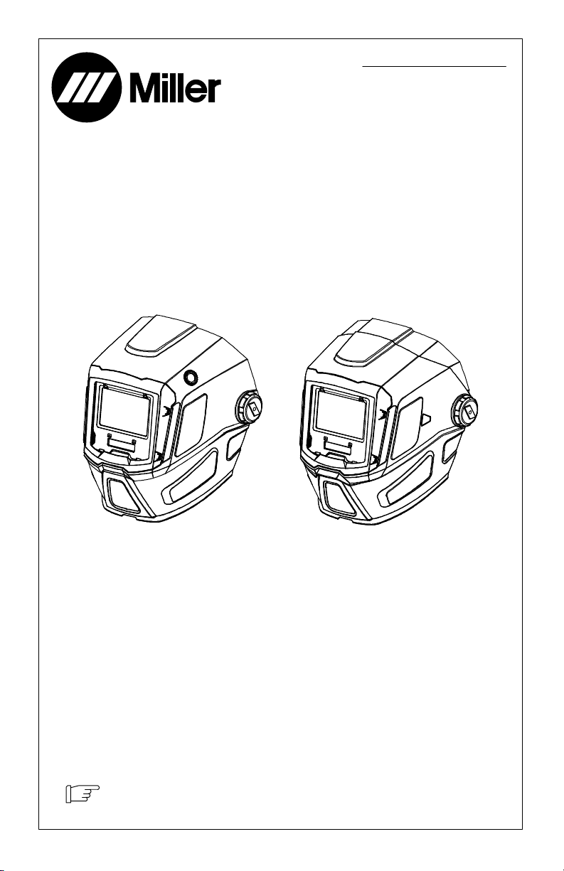
Auto-Darkening Helmets
Model: T94t, T94i Series
T94 T94i
To help us serve you better, go to www.MillerWelds.Com/Register
Page 2

TABLE OF CONTENTS
SECTION 1 − WELDING HELMET SAFETY PRECAUTIONS −
READ BEFORE USING 1........................................................
1-1. Symbol Usage 1............................................................
1-2. Arc Welding Hazards 1.......................................................
1-3. Proposition 65 Warnings 2....................................................
1-4. Lens Shade Selection Table 3.................................................
1-5. Principal Safety Standards 3..................................................
SECTION 2 − CONSIGNES DE SÉCURITÉ POUR
LE CASQUE DE SOUDAGE − LIRE AVANT UTILISATION 4..........................
2-1. Symboles utilisés 4..........................................................
2-2. Dangers relatifs au soudage à l’arc 4...........................................
2-3. Proposition californienne 65 Avertissements 5....................................
2-4. Tableau de sélection d’opacité de lentille 6.......................................
2-5. Principales normes de sécurité 6...............................................
SECTION 3 − SPECIFICATIONS 7.................................................
SECTION 4 − OPERATING INSTRUCTIONS 8......................................
4-1. Helmet Configurations 8......................................................
4-2. Helmet Controls 9...........................................................
4-3. Mode Button And Grind / Low Battery Light 10.....................................
4-4. Mode Control Settings 11......................................................
4-5. Variable Shade Control 12.....................................................
4-6. Lens Delay Control 13.........................................................
4-7. Sensitivity Control 14..........................................................
4-8. Typical Lens Adjustment Procedure 15...........................................
4-9. Info Control Button 16.........................................................
4-10. Clock Control 17.............................................................
4-11. Arc Time And Arc Count Control 18..............................................
SECTION 5 − ADJUSTING HEADGEAR 19..........................................
5-1. Adjusting Headgear On T94 Series Helmets 19....................................
SECTION 6 − REPLACING THE GRINDING SHIELD OR LENS COVERS 20.............
6-1. Replacing Grinding Shield On T94i Helmet 20.....................................
6-2. Replacing Lens Covers On Quick Release Helmets 21.............................
SECTION 7 − REPLACING THE BATTERY 22.......................................
SECTION 8 − INSTALLING OPTIONAL MAGNIFYING LENS 23........................
SECTION 9 − MAINTENANCE 23..................................................
SECTION 10 − TROUBLESHOOTING 24............................................
SECTION 11 − PARTS LISTS 25...................................................
SECTION 12 − LIMITED WARRANTY 28............................................
Page 3
SECTION 1 − WELDING HELMET SAFETY PRECAUTIONS −
READ BEFORE USING
helmet 2018-08
Protect yourself and others from injury — read, follow, and save these important safety
precautions and operating instructions.
1-1. Symbol Usage
DANGER! − Indicates a hazardous
situation which, if not avoided, will
result in death or serious injury. The
possible hazards are shown in the
adjoining symbols or explained in
the text.
Indicates a hazardous situation
which, if not avoided, could result in
death or serious injury. The possible
hazards are shown in the adjoining
symbols or explained in the text.
NOTICE − Indicates statements not related to
personal injury.
Indicates special instructions.
This group of symbols means Warning! Watch
Out! ELECTRIC SHOCK, MOVING PARTS,
and HOT PARTS hazards. Consult symbols
and related instructions below for necessary
actions to avoid the hazards.
1-2. Arc Welding Hazards
Only qualified persons should install, operate, maintain, and repair this equipment. A
qualified person is defined as one who, by possession of a recognized degree, certificate,
or professional standing, or who by extensive knowledge, training and experience, has
successfully demonstrated ability to solve or resolve problems relating to the subject
matter, the work, or the project and has received safety training to recognize and avoid
the hazards involved.
ARC RAYS can burn eyes and skin.
Arc rays from the welding process produce intense visible and invisible (ultraviolet and infrared) rays that can burn eyes and skin. Sparks fly off from the weld.
Wear a welding helmet fitted with a proper shade of filter to protect your face and eyes when
welding or watching (see ANSI Z49.1 and Z87.1 listed in Safety Standards). Refer to Lens
Shade Selection table in Section 1-4.
Wear approved safety glasses with side shields under your helmet.
Use protective screens or barriers to protect others from flash, glare, and sparks; warn
others not to watch the arc.
Wear body protection made from durable, flame−resistant material (leather, heavy cotton,
wool). Body protection includes oil-free clothing such as leather gloves, heavy shirt, cuffless
trousers, high shoes, and a cap.
• Before welding, adjust the auto-darkening lens sensitivity setting to meet the application.
• Stop welding immediately if the auto-darkening lens does not darken when the arc is struck.
NOISE can damage hearing.
Noise from some processes or equipment can damage hearing.
Wear approved ear protection if noise level is high.
OM-255503 Page 1
Page 4

WELDING HELMETS do not provide unlimited eye, ear, and
face protection.
Arc rays from the welding process produce intense visible and invisible (ultraviolet
and infrared) rays that can burn eyes and skin. Sparks fly off from the weld.
Use helmet for welding/cutting applications only. Do not use helmet for laser welding/cutting.
Use impact resistant safety spectacles or goggles and ear protection at all times when using
this welding helmet.
Do not use this helmet while working with or around explosives or corrosive liquids.
This helmet is not rated for overhead welding. Do not weld in the direct overhead position
while using this helmet unless additional precautions are taken to protect yourself from arc
rays, spatter, and other hazards.
Inspect the auto-lens frequently. Immediately replace any scratched, cracked, or pitted cover
lenses or auto-lenses.
Lens and retention components must be installed as instructed in this manual to ensure
compliance with ANSI Z87.1 protection standards.
READ INSTRUCTIONS.
Read and follow all labels and the Owner’s Manual carefully before in-
stalling, operating, or servicing unit. Read the safety information at the beginning of the manual and in each section.
Use only genuine replacement parts from the manufacturer.
Perform installation, maintenance, and service according to the Owner’s Manuals, industry
standards, and national, state, and local codes.
FUMES AND GASES can be hazardous.
Welding produces fumes and gases. Breathing these fumes and gases can be
hazardous to your health.
Keep your head out of the fumes. Do not breathe the fumes.
Ventilate the work area and/or use local forced ventilation at the arc to remove welding fumes
and gases. The recommended way to determine adequate ventilation is to sample for the composition and quantity of fumes and gases to which personnel are exposed.
If ventilation is poor, wear an approved air-supplied respirator.
Read and understand the Safety Data Sheets (SDSs) and the manufacturer’s instructions for
adhesives, coatings, cleaners, consumables, coolants, degreasers, fluxes, and metals.
Work in a confined space only if it is well ventilated, or while wearing an air-supplied respirator.
Always have a trained watchperson nearby. Welding fumes and gases can displace air and
lower the oxygen level causing injury or death. Be sure the breathing air is safe.
Do not weld in locations near degreasing, cleaning, or spraying operations. The heat and rays
of the arc can react with vapors to form highly toxic and irritating gases.
Do not weld on coated metals, such as galvanized, lead, or cadmium plated steel, unless the
coating is removed from the weld area, the area is well ventilated, and while wearing an airsupplied respirator. The coatings and any metals containing these elements can give off toxic
fumes if welded.
1-3. Proposition 65 Warnings
WARNING: Cancer and Reproductive Harm − www.P65Warnings.ca.gov
OM-255503 Page 2
Page 5

1-4. Lens Shade Selection Table
Process
Shielded Metal Arc
Welding (SMAW)
Gas Metal
Arc Welding
(GMAW)
Flux Cored
Arc Welding
(FCAW)
Gas Tungsten Arc
Welding (TIG)
Air Carbon
Arc Cutting (CAC-A)
Plasma Arc
Cutting (PAC)
Plasma Arc Welding
(PAW)
Electrode Size
in. (mm)
Less than 3/32 (2.4)
3/32−5/32 (2.4−4.0)
5/32−1/4 (4.0−6.4)
More than 1/4 (6.4)
Light
Heavy
Arc Current
in
Amperes
Less than 60
60−160
160−250
250−550
Less than 60
60−160
160−250
250−500
Less than 50
50−150
150−500
Less than 500
500−1000
Less than 20
20−40
40−60
60−80
80−300
300−400
400−800
Less than 20
20−100
100−400
400−800
Minimum
Protective
Shade No.
7
8
10
11
7
10
10
10
8
8
10
10
11
4
5
6
8
8
9
10
6
8
10
11
Suggested
Shade No.
(Comfort)*
−−
10
12
14
−−
11
12
14
10
12
14
12
14
4
5
6
8
9
12
14
6−8
10
12
14
Reference: ANSI Z49.1:2012
* Start with a shade that is too dark to see the weld zone. Then, go to a lighter shade which gives a
sufficient view of the weld zone without going below the minimum.
1-5. Principal Safety Standards
Safety in Welding, Cutting, and Allied Processes, ANSI Standard Z49.1, is available as a free download from the American Welding Society at http://www.aws.org or purchased from Global Engineering
Documents (phone: 1-877-413-5184, website: www.global.ihs.com).
Safe Practice For Occupational And Educational Eye And Face Protection, ANSI Standard Z87.1,
from American National Standards Institute, 25 West 43rd Street, New York, NY 10036 (phone:
212-642-4900, website: www.ansi.org).
Industrial Head Protection, ANSI/ISEA Standard Z89.1, from American National Standards Institute,
25 West 43rd Street, New York, NY 10036 (phone: 212-642-4900, website: www.ansi.org).
OM-255503 Page 3
Page 6
SECTION 2 − CONSIGNES DE SÉCURITÉ POUR
LE CASQUE DE SOUDAGE − LIRE AVANT UTILISATION
helmet_2018−08_fre
Pour écarter les risques de blessure pour vous−même et pour autrui — lire, appliquer et ranger en
lieu sûr ces consignes relatives aux précautions de sécurité et au mode opératoire.
2-1. Symboles utilisés
DANGER! − Indique une situation
dangereuse qui si on l’évite pas peut
donner la mort ou des blessures graves.
Les dangers possibles sont montrés par
les symboles joints ou sont expliqués
dans le texte.
Indique une situation dangereuse qui si
on l’évite pas peut donner la mort ou des
blessures graves. Les dangers
possibles sont montrés par les
symboles joints ou sont expliqués dans
le texte.
AVIS − Indique des déclarations pas en relation avec
des blessures personnelles.
Indique des instructions spécifiques.
Ce groupe de symboles veut dire Avertissement!
Attention! DANGER DE CHOC ELECTRIQUE,
PIECES EN MOUVEMENT, et PIECES
CHAUDES. Consulter les symboles et les
instructions ci-dessous y afférant pour les actions
nécessaires afin d’éviter le danger.
2-2. Dangers relatifs au soudage à l’arc
L’installation, l’utilisation, l’entretien et les réparations ne doivent être confiés qu’à des personnes
qualifiées. Une personne qualifiée est définie comme celle qui, par la possession d’un diplôme reconnu,
d’un certificat ou d’un statut professionnel, ou qui, par une connaissance, une formation et une expérience approfondies, a démontré avec succès sa capacité à résoudre les problèmes liés à la tâche,
le travail ou le projet et a reçu une formation en sécurité afin de reconnaître et d’éviter les risques
inhérents.
LES RAYONS DE L’ARC peuvent provoquer des brûlures
dans les yeux et sur la peau.
Le rayonnement de l’arc du procédé de soudage génère des rayons visibles et invisibles
intenses (ultraviolets et infrarouges) susceptibles de provoquer des brûlures dans les yeux et
sur la peau. Des étincelles sont projetées pendant le soudage.
Porter un casque de soudage muni d’un écran de filtre approprié pour protéger votre visage et vos yeux
pendant le soudage ou pour regarder (voir ANSI Z49.1 et Z87.1 énuméré dans les normes de sécurité).
Se reporter au tableau de sélection des filtres, Section 2-4.
Porter des protections approuvées pour les oreilles si le niveau sonore est trop élevé.
Avoir recours à des écrans protecteurs ou à des rideaux pour protéger les autres contre les rayon-
nements les éblouissements et les étincelles ; prévenir toute personne sur les lieux de ne pas regarder
l’arc.
Porter un équipement de protection pour le corps fait d’un matériau résistant et ignifuge (cuir, coton ro-
buste, laine). La protection du corps comporte des vêtements sans huile comme par ex. des gants de cuir,
une chemise solide, des pantalons sans revers, des chaussures hautes et une casquette.
Avant de souder, régler la sensibilité du verre à obscurcissement automatique en fonction de l’application.
Si le verre ne s’obscurcit pas à l’amorçage de l’arc, cesser immédiatement de souder.
OM-255503 Page 4
Le BRUIT peut endommager l’ouïe.
Le bruit produit par certains procédés ou équipements peut endommager l’ouïe.
Porter des protecteurs antibruit approuvés si le bruit est trop élevé.
Page 7
LES CASQUES DE SOUDAGE ne procurent pas une
protection absolue des yeux, des oreilles ou du visage.
Le rayonnement de l’arc du procédé de soudage génère des rayons visibles et invisibles
intenses (ultraviolets et infrarouges) susceptibles de provoquer des brûlures dans les yeux et
Utilisez uniquement un casque pour les applications de soudage/découpe.
pour le soudage/ découpage laser.
Porter des lunettes de sécurité et des protecteurs antibruit résistants aux chocs en tout temps pendant
l’utilisation de ce casque de soudage.
Ne pas utiliser ce casque de soudage pendant la manutention ou le travail à proximité de liquides
explosifs ou corrosifs.
Ce casque n’est pas évalué pour le soudage à la verticale. Ne pas souder dans une position directement à la
verticale tout en utilisant ce casque à moins d’avoir pris des précautions supplémentaires au préalable afin de
se protéger contre les rayonnements de l’arc, des projections et d’autres risques.
Vérifier fréquemment l’état de la cellule à obscurcissement automatique. Remplacer immédiatement
toute loupe ou cellule égratignée, fissurée ou piquée.
La lentille et les composants de retention doivent être installés comme indiqué dans ce manuel pour
assurer la conformité avec les normes de protection ANSI Z87.1.
sur la peau. Des étincelles sont projetées pendant le soudage.
Ne pas utiliser de casque
LIRE LES INSTRUCTIONS.
Lire et appliquer les instructions sur les étiquettes et le Mode d’emploi avant l’instal-
lation, l’utilisation ou l’entretien de l’appareil. Lire les informations de sécurité au début
du manuel et dans chaque section.
N’utiliser que les pièces de rechange recommandées par le constructeur.
Effectuer l’installation, l’entretien et toute intervention selon les manuels d’utilisateurs, les normes
nationales, provinciales et de l’industrie, ainsi que les codes municipaux.
LES FUMÉES ET LES GAZ peuvent être dangereux.
Le soudage génère des fumées et des gaz. Leur inhalation peut être dangereux pour votre
santé.
Eloigner votre tête des fumées. Ne pas respirer les fumées.
À l’intérieur, ventiler la zone et/ou utiliser une ventilation forcée au niveau de l’arc pour l’À l’intérieur, ventiler
la zone et/ou utiliser une ventilation forcée au niveau de l’arc pour l’évacuation des fumées et des gaz de
soudage. Pour déterminer la bonne ventilation, il est recommandé de procéder à un prélèvement pour la
composition et la quantité de fumées et de gaz auxquelles est exposé le personnel.
Si la ventilation est médiocre, porter un respirateur anti-vapeurs approuvé.
Lire et comprendre les fiches de données de sécurité et les instructions du fabricant concernant les
adhésifs, les revêtements, les nettoyants, les consommables, les produits de refroidissement, les dégraisseurs, les flux et les métaux.
Travailler dans un espace fermé seulement s’il est bien ventilé ou en portant un respirateur à alimentation
d’air. Demander toujours à un surveillant dûment formé de se tenir à proximité. Des fumées et des gaz de
soudage peuvent déplacer l’air et abaisser le niveau d’oxygène provoquant des blessures ou des
accidents mortels. S’assurer que l’air de respiration ne présente aucun danger.
Ne pas souder dans des endroits situés à proximité d’opérations de dégraissage, de nettoyage ou de pul-
vérisation. La chaleur et les rayons de l’arc peuvent réagir en présence de vapeurs et former des gaz hautement toxiques et irritants.
Ne pas souder des métaux munis d’un revêtement, tels que l’acier galvanisé, plaqué en plomb ou au
cadmium à moins que le revêtement n’ait été enlevé dans la zone de soudure, que l’endroit soit bien ventilé,
et en portant un respirateur à alimentation d’air. Les revêtements et tous les métaux renfermant ces
éléments peuvent dégager des fumées toxiques en cas de soudage.
2-3. Proposition californienne 65 Avertissements
AVERTISSEMENT : cancer et troubles de la reproduction − www.P65Warnings.ca.gov
OM-255503 Page 5
Page 8

2-4. Tableau de sélection d’opacité de lentille
Procédé Taille
Soudage à l’arc avec
électrode enrobée
(SMAW)
Soudage à l’arc sous
gaz avec fil plein
(GMAW)
Soudage à l’arc avec fil
fourré (FCAW)
Soudage à l’arc sous
gaz avec électrode au
tungstène (TIG)
Coupage à l’arc avec
électrode au carbone et
jet d’air (AAC)
Coupage au plasma
(PAC)
Soudage au plasma
(PAW)
d’électrode
po. (mm)
Moins que 3/32 (2,4)
3/32−5/32 (2,4−4,0)
5/32−1/4 (4,0−6,4)
Plus que 1/4 (6,4)
Légère
Lourde
Courant
d’arc en
ampères
Moins que 60
60−160
160−250
250−550
Moins que 60
60−160
160−250
250−500
Moins que 50
50−150
150−500
Moins que 500
500−1000
Moins que 20
20−40
40−60
60−80
80−300
300−400
400−800
Moins que 20
20−100
100−400
400−800
Opacité de
protection
minimum
No.
7
8
10
11
7
10
10
10
8
8
10
10
11
4
5
6
8
8
9
10
6
8
10
11
Opacité
suggérée
No.
(Confort)*
−−
10
12
14
−−
11
12
14
10
12
14
12
14
4
5
6
8
9
12
14
6−8
10
12
14
Référence : ANSI Z49.1:2012
* Commencer avec une opacité plus élevée pour voir la zone de soudage puis utiliser une lentille plus claire
permettant de voir suffisamment la zone de soudage, sans aller au dessous du minimum.
2-5. Principales normes de sécurité
Safety in Welding, Cutting, and Allied Processes, ANSI Standard Z49.1, is available as a free download from the
American Welding Society at http://www.aws.org or purchased from Global Engineering Documents (phone:
1-877-413-5184, website: www.global.ihs.com).
Safe Practice For Occupational And Educational Eye And Face Protection, ANSI Standard Z87.1, from American
National Standards Institute, 25 West 43rd Street, New York, NY 10036 (phone: 212-642-4900, website: www.ansi.org).
OM-255503 Page 6
Page 9

SECTION 3 − SPECIFICATIONS
Specification
Viewing Field 3.81 x 2.62 in
Reaction Time 0.0000500 sec (1/20,000)
Available Shades
All Shades Provide
Continuous
UV And IR
Protection.
Sensitivity Control Adjustable For Varying Ambient Light And Welding Arc
Delay Control Slows Lens Dark-To-Light State Between 0.1 And 1.0 Seconds
Automatic Power Off Shuts Lens Off 45 Minutes After Last Arc Is Struck
Low Battery Light Red LED Illuminates To Indicate 2−3 Days Remaining Battery Life
Power Supply Panasonic CR2450 Lithium Battery
Sensors Independent/Redundant (Four)
Operating
Temperature
Storage
Temperature
Total Weight T94: 21 oz (595 g)
Standards Meets ANSI Z87.1+, CSA Z94.3
Warranty Three Years From Date Of Purchase (Section 12)
When Stored In Extremely Cold Temperatures, Warm Helmet To
Ambient Temperature Before Welding.
When Stored In Extremely Cold Temperatures, Warm Helmet To
Ambient Temperature Before Welding.
Darkened State: No. 8 − No. 13
Darkened State: No. 5 − No. 8
Darkened State: No. 8 − No. 13
(Miller Part No. 217043)
14F to 131F / −10C to +55C
−4F to 158F / −20C to +70C
T94
T94i
(97 x 60mm)
Weld Mode
Light State: No. 3
Cut Mode
Light State: No. 3
Grind Mode
Light State: No. 3
X-Mode
Light State: No. 3
T94i: 25.7 oz (729 g)
OM-255503 Page 7
Page 10
SECTION 4 − OPERATING INSTRUCTIONS
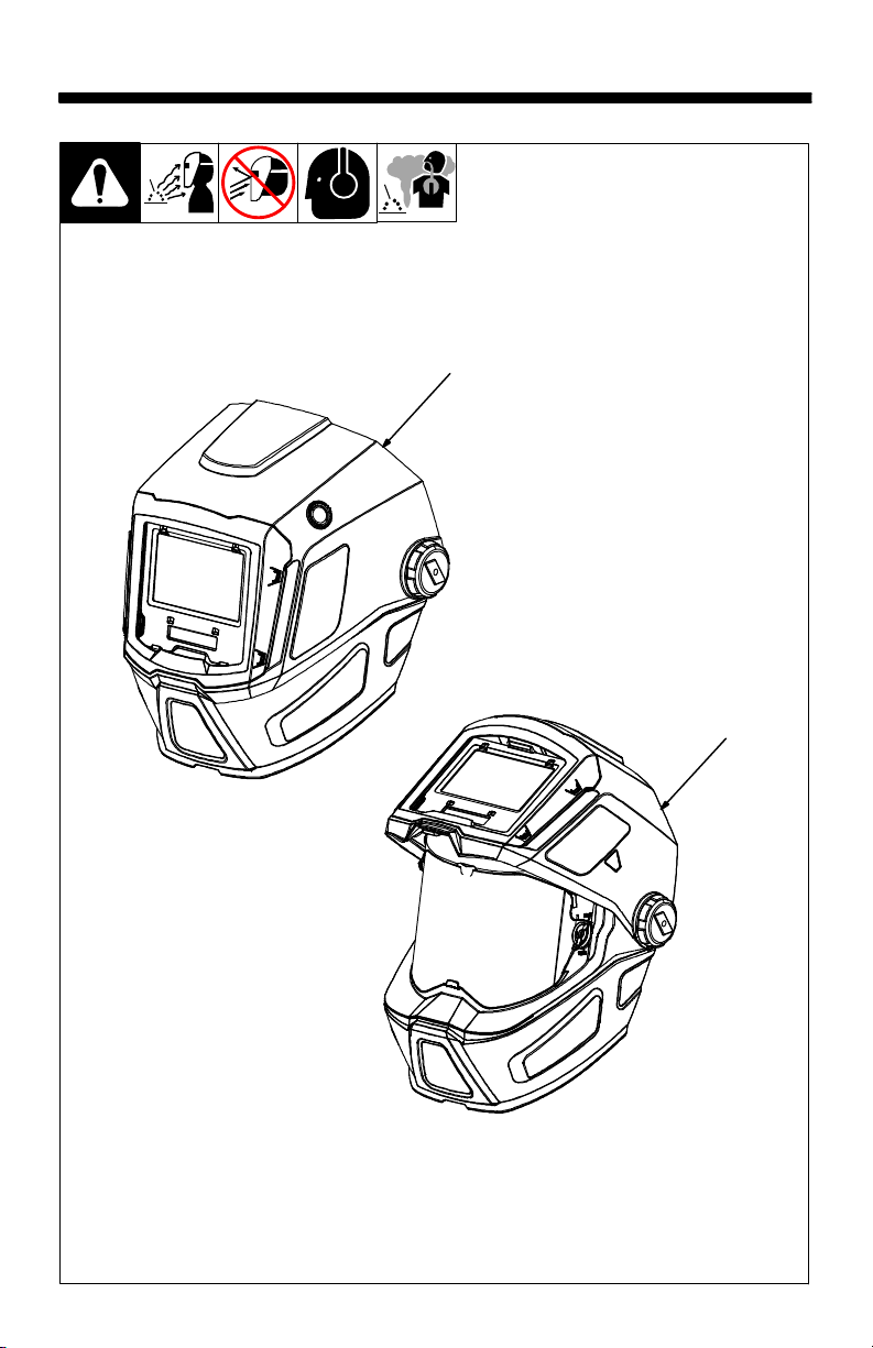
4-1. Helmet Configurations
1 T94 Helmet
The T94 helmet features a fixed posi-
tion, auto-darkening lens and is
designed for standard welding applications.
2 T94i Helmet
The T94i helmet features a flip-up
auto-darkening lens and a separate,
1
clear grinding shield. Flip the lens up
when grinding and performing other
non-welding work. Flip the lens down
when welding or cutting.
OM-255503 Page 8
2
260482-2 / 260483-7
Page 11

4-2. Helmet Controls
7
2
4
1 3
The lens on T94 Series Helmets turns on (darkens)
automatically when welding
begins and turns off when
welding stops.
1 Mode Button (On/Off)
(See Sections 4-3 and
4-4)
2 Grind Mode / Low
Battery Light
(Section 4-3)
6
3 Adjust Button
4 Increase (+) Button
5 Decrease (-) Button
6 Info Control Button
(See Section 4-9)
7 External Grinding
Mode Button (Section
4-4)
5
260482-2 / 260482-4
The External Grinding
Mode button is not
available on the T94i
helmet.
The lens assembly
saves the shade, sensitivity, and delay
settings.
OM-255503 Page 9
Page 12

4-3. Mode Button And Grind / Low Battery Light
1
The auto-darkening lens
on T94 Series Helmets
turns on (darkens) automatically when welding
begins and turns off
when welding stops.
1 Mode Button
Press Mode button to check
if the lens is working properly
OM-255503 Page 10
and to begin Mode and Info
adjustments.
When the Mode button is
pressed, the helmet control
display will appear. Do not
use the helmet if the lens
does not function as described. (See Section 10,
Troubleshooting.)
2 Grind / Low Battery Light
2
260482-4
The Grind / Low Battery light
blinks when the lens is in the
Grind mode. Light stays on
when 2−3 days of battery life
remain.
If battery power is low, replace with CR2450 lithium
battery (1 required − Miller
Part No. 217043). See Section 7.
Page 13

4-4. Mode Control Settings
2
1
1 Mode Button
2 External Grind Mode
Button
Press Mode button to select
the mode appropriate for the
work activity:
Weld Mode − used for most
welding applications. In this
mode the lens turns on
when it optically senses a
welding arc. Adjust shade,
sensitivity, and delay settings as needed.
Cut Mode − used for cutting
applications. In this mode
the lens turns on when it optically senses a cutting arc.
Adjust shade, sensitivity,
and delay settings as needed.
! If nearby objects may
inadvertently contact
the external Grind
Mode button while
you are welding, unplug the Grind Mode
button to prevent accidental activation of
the Grind mode.
Grind Mode − used for met-
al grinding applications. In
this mode the shade is fixed
shade No. 3. No lens adjustments are possible.
Use external Grind Mode
button to select grinding
mode without raising helmet.
260482-2 / 260482-4
To use Grind mode, press
and hold the external Grind
button for two seconds.
Press Grind Mode button
again to turn off Grind mode.
X-Mode − used for outdoor
or low current welding applications. In this mode the
lens turns on when it senses
weld current. Adjust shade,
sensitivity, and delay settings as needed.
Nearby welding may af-
fect helmet operation
when lens is in X-Mode.
Stay at least 12 ft (3.7
m) away from other
welding activity.
OM-255503 Page 11
Page 14

4-5. Variable Shade Control
21
1 Mode Button
2 Increase (+) And
Decrease (-) Buttons
Use the + and − adjustment
buttons to adjust the lens
shade in the darkened state.
Use the table in Section 1-4
to select proper shade control setting based on your
welding process. The shade
ranges for each mode are as
follows:
Weld − No. 8 − No. 13
Cut − No. 5 − No. 8
OM-255503 Page 12
Grind − No. 3 only
X-Mode − No. 8 − No. 13
Start at the highest setting
and adjust lighter to suit the
application and your personal preference.
Variable Shade Adjustment Procedure
Press Mode (On/Off)
button to turn lens On.
Helmet control display
will appear.
260482-4
Press Mode Button to
select desired function:
Weld, Cut, or X-Mode.
Use + and − adjustment
buttons to select desired
shade.
Begin welding or contin-
ue with other lens adjustments.
Page 15

4-6. Lens Delay Control
1 Mode Button
2 Adjust Button
3 Increase (+) And De-
crease (-) Buttons
Select Delay by pressing the
Adjust button. Use the + / −
buttons to adjust the time for
the lens to switch to the clear
state after welding or cutting.
The delay is particularly useful in eliminating bright
after-rays present in higher
amperage applications
where the molten puddle remains bright momentarily
after welding. Use the + / -
buttons to adjust delay from
0 to 10 (0.1 to 1.0 second).
The delay ranges for each
mode are as follows:
Weld, Cut, X-Modes − 0 −
10
Grind Mode − No delay ad-
justment
There is no lens delay
adjustment in the Grind
mode.
Lens Delay Adjustment
Procedure
Press Mode (On/Off)
2
button to turn lens On.
Helmet control display
will appear.
Press Mode button to
select desired function:
Weld, Cut, or X-Mode.
Use Adjust button to se-
lect delay, and then
adjust to desired delay
using + / − buttons.
Begin welding or contin-
ue with other lens
adjustments.
31
260482-4
OM-255503 Page 13
Page 16

4-7. Sensitivity Control
1 Mode Button
2 Adjust Button
3 Increase (+) And
Decrease (-) Buttons
Use control to make the lens
more responsive to different
light levels in various welding
processes. Use a Mid-
Range or 30−50% sensitiv-
ity setting for most appli-
cations.
It may be necessary to adjust
helmet sensitivity to accommodate different lighting conditions or if lens is flashing
On and Off.
The sensitivity ranges for
each mode are as follows:
Weld, Cut, X-Modes − 0 − 10
Stick Electrode Mid-Range
Short Circuiting (MIG) Low/Mid-Range
Pulsed & Spray (MIG) Mid-Range
Gas Tungsten Arc (TIG) Mid/High-Range
Plasma Arc Cutting/Welding Low/Mid-Range
OM-255503 Page 14
Grind Mode − No sensitivity
adjustment
! Do not weld in the
Grind mode; the lens
will not darken.
Sensitivity Adjustment
Procedure
Adjust helmet sensitivity
in lighting conditions helmet will be used in.
Press Mode (On/Off)
button to turn lens On.
Helmet control display
will appear.
Press Mode button to
select desired function:
Weld, Cut, or X-Mode.
Use the Adjust button to
select sensitivity, then
Recommended Sensitivity Settings
2
use the +/− buttons to
adjust sensitivity to the
lowest setting.
31
Face the helmet in the di-
rection of use, exposing
it to the surrounding light
conditions.
Press + button until the
lens darkens, then press
− button until lens clears.
Helmet is ready for use.
Slight readjustment may be
necessary for certain applications or if lens is flashing
on and off.
Reduce Sensitivity set-
ting if lens stays dark
longer than Delay setting.
260482-4
Page 17

4-8. Typical Lens Adjustment Procedure
Lens assembly displays
prior settings when turned
On. Retained settings are
not shown in example.
In the Grind mode the lens is
a fixed shade No. 3. No lens
adjustments are possible.
Adjusting Lens Assembly:
Turn lens On. Display
screen appears.
Select mode (Weld, Cut,
Grind, X-Mode).
Select shade by pressing
+/− buttons.
Select Delay by pressing
Adjust until Delay appears,
then use the +/− buttons to
set.
Select Sensitivity by
pressing Adjust until Sens
appears, then use the +/−
buttons to set.
Press Adjust until full
screen appears to confirm
settings.
Begin work.
260482-4
OM-255503 Page 15
Page 18

4-9. Info Control Button
1
1 Info Control Button
Press Info Control button to
select from the following
functions:
Clock − displays actual
time of day in 24 hour format. See Section 4-10 to
set clock.
OM-255503 Page 16
Arc Time − records the
amount of time the lens
assembly is in the dark
state (exposed to arc). See
Section 4-11 to reset Arc
Time.
260483-6
Arc Count − records the
number of times the lens
darkens. See Section 4-11
to reset the Arc Count.
Lens automatically
exits the Info function
after 30 seconds of inactivity.
Page 19

4-10. Clock Control
1
1 Mode Button
2 Info Control Button
3 Adjust Button
4 Increase (+) And De-
crease (-) Buttons
Clock Procedure
2
Press Mode (On/Off)
button to turn helmet On.
Helmet control display
will appear.
Press Info Control but-
ton once. Clock is displayed on screen.
Clock displays time in 24
hour format.
Press and hold Adjust
button until only the hour
digits are displayed.
Press + / − buttons to
change hour setting.
3 4
260483-6
Press Adjust button to
switch to minute setting.
Press + / − buttons to
change minute setting.
Press Info Control but-
ton to set.
Press Mode button to re-
turn to main control display.
OM-255503 Page 17
Page 20

4-11. Arc Time And Arc Count Control
1
The arc time function records the amount of time the
lens assembly is dark (exposed to an arc). The arc
count function records the
number of times the lens
darkens.
1 Mode Button
2 Info Control Button
OM-255503 Page 18
2
3 Adjust Button
Arc Time / Count Procedure
Press Mode (On/Off)
button to turn helmet On.
Helmet control display
will appear.
3
260483-5
Press Info Control but-
ton repeatedly until Time
or Count is displayed on
screen.
Press and hold the Ad-
just button to reset to
zero.
Press the Mode button
when finished.
Page 21

SECTION 5 − ADJUSTING HEADGEAR
5-1. Adjusting Headgear On T94 Series Helmets
1
4
2
There are four headgear
adjustments: headgear
top, tightness, angle adjustment, and distance
adjustment.
1 Headgear Top
Adjusts headgear for proper
depth on the head to ensure
correct balance and stability.
2 Headgear Tightness
To adjust, turn the adjusting
knob located on the back of
the headgear left or right to
desired tightness.
3 Angle Adjustment (Not
Shown)
Seven slots on the right side
of the headband provide adjustment for the forward tilt of
the helmet. To adjust, lift and
reposition the control arm to
the desired position.
4 Distance Adjustment
Adjusts the distance be-
tween the face and the lens.
To adjust, press black tabs
on the top and bottom of the
pivot point and use other
hand to slide headgear forward or backward. Release
tabs. (Both sides must be
equally positioned for proper
vision.)
Numbers on the adjust-
ment slides indicate set
position so both sides
can be adjusted equally.
260482-7
OM-255503 Page 19
Page 22

SECTION 6 − REPLACING THE GRINDING SHIELD OR
LENS COVERS
6-1. Replacing Grinding Shield On T94i Helmet
! Never use the auto-dark-
ening lens without the inside and outside lens
covers properly installed.
Welding spatter will damage the auto-darkening
lens and void the
warranty.
1 Grinding Shield
2 Retaining Clip
3 Tab
Rotate both retaining clips to the
Open position.
Gently push shield toward bot-
tom tab and remove shield from
1
3
helmet.
Remove retaining clips from
shield. Install clips in same location on new shield. (Retaining
clips are not interchangeable.)
Install new shield in helmet and
rotate clips to the Lock position.
Tear-Away Protective Sheets
Tear-away sheets are available
2
to prolong the life of the grinding
shield (see Parts List).
To install tear-away sheets, pull
backing from both sides of the
tear-away, remove white adhesive backing strips, and
place on clear shield.
OM-255503 Page 20
260483-7
Page 23

6-2. Replacing Lens Covers On Quick Release Helmets
2
1
! Never use the
auto-darkening lens
without the inside
and outside lens covers properly
installed. Welding
spatter will damage
the auto-darkening
lens and void the
warranty.
Outside Lens Cover
1 Lens Holder
2 Lens Holder Release
Points
3 Outside Lens Cover
Remove lens holder by
pulling the holder away
from the helmet on either
side of lens holder.
2
4
3
Remove lens cover from
shell by pulling top center of
lens. Replace lens cover in
lens holder by placing one
edge in place, bending lens
cover, and inserting opposite edge into lens holder
channel. Reinstall lens
holder in helmet.
Inside Lens Cover
4 Auto-Darkening Lens
5 Inside Lens Cover
Remove the inside lens
cover by pulling top center
of lens cover from lens
holding channels.
Replace the lens cover by
gently bowing it in the center and inserting it, one end
6
5
260483-8 / 260482-10
at a time, into the lens holding channels.
Be sure the cover lens
is seated properly to
prevent fogging.
Auto-Darkening Lens
6 Lens Release Tab
Remove lens holder and
outside lens cover using instructions above. Press up
on lens release tab and
push auto-darkening lens
assembly from the inside to
remove.
Replace the lens by aligning it on the release tabs
and pressing it in until it
snaps into place.
OM-255503 Page 21
Page 24

SECTION 7 − REPLACING THE BATTERY
+
1
To replace the battery, remove the auto-darkening
lens assembly (see Section 6).
1 Battery Tray
After removing the lens assembly, slide the battery
OM-255503 Page 22
holding tray out and remove the old battery.
Replace with Panasonic
CR2450 lithium type battery (1 required) (Miller Part
No. 217043).
Be sure Positive (+)
Be sure Positive (+)
side of battery
faces up.
260482-11
side of the battery
faces up (toward inside
of helmet).
Reinstall the battery tray.
To test battery, press the
Mode button. The display
screen should turn on. Reinstall the lens assembly.
Page 25

SECTION 8 − INSTALLING OPTIONAL MAGNIFYING LENS
1 Optional Magnifying Lens
Starting at the bottom, slide magni-
fying lens into the helmet retaining
brackets. Align the magnifying lens
with the auto-darkening lens assembly. Reverse procedure to remove magnifying lens.
To prevent lens fogging, install
flat side of magnifying lens toward auto-darkening lens.
1
260482-12
SECTION 9 − MAINTENANCE
NOTICE − Never use solvents or abrasive cleaning detergents.
NOTICE − Do not immerse the lens assembly in water.
The helmet requires little maintenance. However, for best performance clean after each use. Using
a soft cloth dampened with a mild soap and water solution, wipe the cover lenses clean. Allow to air
dry. Occasionally, the filter lens and sensors should be cleaned by gently wiping with a soft, dry cloth.
OM-255503 Page 23
Page 26

SECTION 10 − TROUBLESHOOTING
Trouble Remedy
Auto lens not On – autolens settings do not appear when the Mode button is pressed.
Not switching – auto-lens
stays light and will not
darken when welding.
Not Switching – auto-lens
stays dark after the weld
arc is extinguished, or the
auto-lens stays dark when
no arc is present.
Sections of the auto-lens
are not going dark, distinct
lines separate the light and
dark areas.
Switching or Flickering –
the auto-lens darkens then
lightens while the welding
arc is present.
Check battery and verify it is in good condition and installed properly.
Check battery surfaces and contacts and clean if necessary.
Check battery for proper contact and gently adjust contact points
if necessary. This is particularly important if the helmet has been
dropped.
Stop welding immediately: Press the Mode (On/Off) button.
If power is On, review the sensitivity recommendations and adjust
sensitivity.
Clean lens cover and sensors of any obstructions. Make sure the
sensors are facing the arc. Angles of 45 or more may not allow
the arc light to reach the sensors.
Fine-tune the sensitivity setting in small increments. In extreme
light conditions, it may be necessary to reduce the surrounding
light levels.
Stop welding immediately: The auto-lens may be cracked which
can be caused by the impact of dropping the helmet.
Weld spatter on the auto lens may also cause cracking. (The lens
may need to be replaced; most cracked lenses are not covered by
warranty).
Review the sensitivity setting recommendations and increase the
sensitivity if possible. Be sure the arc sensors are not being
blocked from direct access to the arc light.
Check the lens cover for dirt and spatter that may be blocking the
arc sensors. Increasing Lens Delay 0.1 − 0.3 second may also
reduce switching.
Inconsistent or lighter
auto-lens shading in the
dark state, noticeable on
the outside edges and corners.
OM-255503 Page 24
Referred to as an angle of view effect, auto-darkening lenses
have an optimum viewing angle.
The optimum viewing angle is perpendicular or 90 to the surface
of the auto-lens. When that angle of view varies in the dark-state,
welders may notice slightly lighter areas at the outside edges and
the corners of the lens. This is normal and does not represent any
health or safety hazard.
This effect may also be more noticeable in applications where
magnifying lenses are used.
Page 27

SECTION 11 − PARTS LISTS
7
8
9
8
1
6
5
10
2
3
Miller
11
4
13
Figure 10-1. T94 Auto-Darkening Welding Helmet
OM-255503 Page 25
12
Ref. 260482
Page 28

Item
No. Quantity
Part
No.
Description
Figure 10-1. T94 Auto-Darkening Welding Helmet
1 258864 Shell, Helmet T94 (Includes Item 6) 1............ ......... .................
2 216327 Lens Cover, Inside 4-1/4 x 2-1/2 in (5 Per Pkg.) 1............ ......... .......
3 260557 Lens Assembly, ADF T94 W/Cable 1............ ......... .................
4 260197 Covers, Side Window 2............ ......... .............................
5 265304 Lens Cover, Front T94 (5 Per Pkg.) 1............ ......... .................
6 265309 Lens Holder, Front T94 1............ ......... ...........................
7 260486 Headgear, Gray (Includes) 1............ ......... ........................
8 *265891 Kit, Headgear Adjust Angle 1........... ........... .....................
9 770249 Headband, Fabric 1............ ........... ..............................
079975 Replacement O-rings For Kit 256178 (5 Per Pkg.) 1.............. ......... .....
10 259574 Tray, Battery 1........... ......... ....................................
217043 Battery, Lithium (CR2450) 1.............. ......... .........................
11 770250 Helmet Bag − Miller 1........... ......... ..............................
♦222003 Adapters, Hard Hat (Not Shown) 1............ ......... ...................
12 256179 Button, Grind Mode 1........... ......... ..............................
13 ♦212235 Lens, 0.75 Magnification 1......... ......... ..........................
13 ♦212236 Lens, 1.00 Magnification 1......... ......... ..........................
13 ♦212237 Lens, 1.25 Magnification 1......... ......... ..........................
13 ♦212238 Lens, 1.50 Magnification 1......... ......... ..........................
13 ♦212239 Lens, 1.75 Magnification 1......... ......... ..........................
13 ♦212240 Lens, 2.00 Magnification 1......... ......... ..........................
13 ♦212241 Lens, 2.25 Magnification 1......... ......... ..........................
13 ♦212242 Lens, 2.50 Magnification 1......... ......... ..........................
* Adjustment Hardware Kit With O-rings.
♦Optional
OM-255503 Page 26
Page 29

12
11
10
14
2
1
2
13
12
5
7
8
9
6
15
4
3
Figure 10-2. T94i Auto-Darkening Welding Helmet
OM-255503 Page 27
Ref. 260483
Page 30

Item
No. Quantity
Part
No.
Description
Figure 10-2. T94i Auto-Darkening Welding Helmet
1 258854 Shell, Helmet T94i (Includes Item 9) 1............ ......... ................
2 245819 Clip, Retaining Grinding Shield 2............ ......... .....................
3 258979 Lens, Grinding Shield (Clear) 1............ ......... ......................
4 ♦258853 Shield, Grinding Tear Away 1.......... ......... ........................
5 216327 Lens Cover, Inside 4−3/16 in x 2−1/2 in 1............ ......... .............
6 259572 Lens Assembly, ADF T94i Without Cable 1............ ......... ............
217043 Battery, Lithium (CR2450) 1.............. ......... .........................
7 259574 Tray, Battery T94i 1............ ......... ................................
8 265304 Lens Cover, Front 1............ ......... ...............................
9 265309 Lens Holder, Front 1............ ......... ...............................
10 260197 Covers, Side Window 2........... ......... .............................
11 260486 Headgear, Gray (Includes) 1........... ......... ........................
12 *265891 Kit, Headgear Adjust Angle 1.......... ........... ......................
13 770249 Headband, Fabric 1........... ........... ..............................
079975 Replacement O-rings For Kit 256178 (5 Per Pkg.) 1.............. ......... .....
14 770250 Bag, Helmet (Miller Logo) 1........... ......... .........................
♦222003 Adapters, Hard Hat (Not Shown) 1............ ......... ...................
15 ♦212235 Lens, 0.75 Magnification 1......... ......... ..........................
15 ♦212236 Lens, 1.00 Magnification 1......... ......... ..........................
15 ♦212237 Lens, 1.25 Magnification 1......... ......... ..........................
15 ♦212238 Lens, 1.50 Magnification 1......... ......... ..........................
15 ♦212239 Lens, 1.75 Magnification 1......... ......... ..........................
15 ♦212240 Lens, 2.00 Magnification 1......... ......... ..........................
15 ♦212241 Lens, 2.25 Magnification 1......... ......... ..........................
15 ♦212242 Lens, 2.50 Magnification 1......... ......... ..........................
* Adjustment Hardware Kit With O-rings.
♦Optional
SECTION 12 − LIMITED WARRANTY
LIMITED WARRANTY – Subject to the terms and conditions below, Miller
Electric Mfg. LLC, Appleton, Wisconsin, warrants to its original retail purchaser that the new Miller equipment sold after the effective date of this
limited warranty is free of defects in material and workmanship at the time
it is shipped by Miller. THIS WARRANTY IS EXPRESSLY IN LIEU OF ALL
OTHER WARRANTIES, EXPRESS OR IMPLIED, INCLUDING THE
WARRANTIES OF MERCHANTABILITY AND FITNESS.
Miller auto-darkening lens helmets are warranted for 3 years from the date
of purchase. Proof of purchase is required for warranty transactions so it
is imperative that a copy of the original invoice or sales receipt be retained.
For warranty transactions, contact your Miller Distributor.
Miller Helmet Warr 2018-01
OM-255503 Page 28
Effective January 1, 2018
Page 31

OM-255503 Page 29
Page 32

For product information,
Owner’s Manual translations,
and more, visit
www.MillerWelds.com
®
Miller Electric Mfg. LLC
An Illinois Tool Works Company
1635 West Spencer Street
Appleton, WI 54914 USA
ORIGINAL INSTRUCTIONS © 2018 Miller Electric Mfg. LLC
 Loading...