

February 1982 FORM: OM-1517B
Effective With Serial No. JB502167
MODEL
SWINGARC DUAL 12 SWINGARC DUAL 16

OWNER'S MANUAL

MILLER ELECTRIC MFG. CO.
718 S. BOUNDS ST. P.O. Box 1079 APPLETON, WI 54912 USA
NWSA CODE NO. 4579 PRINTED IN U.S.A.
LIMITED WARRANTY
K Kak K Kak
EFFECTIVE: JUNE 1, 1979
This warranty supersedes all previous MILLER warranties and is exclusive with no other guarantees or warranties expressed or implied.
THE ARE AND AND A AND
LIMITED WARRANTY-Subject to the terms and conditions hereof, Miller Electric Mfg. Co., Appleton, Wisconsin warrants to its Distributor/Dealer that all new and unused Equipment furnished by Miller is free from defect in workmanship and material as of the time and place of delivery by Miller. No warranty is made by Miller with respect to engines, trade accessories or other items manufactured by others. Such engines, trade accessories and other items are sold subject to the warranties of their respective manufacturers, if any . All engines are warranted by their manufacturer for one year from date of original purchase.
Except as specified below, Miller's warranty does not apply to components having normal useful life of less than one (1) year, such as spot welder tips, relay and contactor points, MILLERMATIC parts that come in contact with the welding wire including nozzles and nozzle insulators where failure does not result from defect in workmanship or material.
Miller shall be required to honor warranty claims on warranted Equipment in the event of failure resulting from a defect within the following periods from the date of delivery of Equipment to the original user:
- 1. Arc welders, power sources and components . . 1 year
- 2. Original main power rectifiers ....................................
- 3. All welding guns and feeder/guns ....................................
- 4. All other Millermatic Feeders ....................................
- 5. Replacement or repair parts, exclusive of labor, 60 days
- 6. Batteries...................................
- 0. Dattelles.................................
provided that Miller is notified in writing within thirty (30) days of the date of such failure.
As a matter of general policy only, Miller may honor claims submitted by the original user within the foregoing periods.
In the case of Miller's breach of warranty or any other duty with respect to the quality of any goods, the exclusive remedies therefore shall be, at Miller's option (1) repair or (2) replacement or, where authorized in writing by Miller in appropriate cases, (3) the reasonable cost of repair or replacement at an authorized Miller service station or (4) payment of or credit for the purchase price (less reasonable depreciation based upon actual use) upon return of the goods at Customer's risk and expense. Upon receipt of notice of apparent defect or failure, Miller shall instruct the claimant on the warranty claim procedures to be followed.
ANY EXPRESS WARRANTY NOT PROVIDED HEREIN AND ANY IMPLIED WARRANTY, GUARANTY OR REPRESENTA-TION AS TO PERFORMANCE, AND ANY REMEDY FOR BREACH OF CONTRACT WHICH, BUT FOR THIS PROVISION, MIGHT ARISE BY IMPLICATION, OPERATION OF LAW, CUSTOM OF TRADE OR COURSE OF DEALING, INCLUDING ANY IMPLIED WARRANTY OF MERCHANTABILITY OR OF FITNESS FOR PARTICULAR PURPOSE, WITH RESPECT TO ANY AND ALL EQUIPMENT FURNISHED BY MILLER IS EX-CLUDED AND DISCLAIMED BY MILLER.
Hat the the that the that that the the
EXCEPT AS EXPRESSLY PROVIDED BY MILLER IN WRITING, MILLER PRODUCTS ARE INTENDED FOR ULTIMATE PURCHASE BY COMMERCIAL/INDUSTRIAL USERS AND FOR OPERATION BY PERSONS TRAINED AND EXPERIENCED IN THE USE AND MAINTENANCE OF WELDING EQUIPMENT AND NOT FOR CONSUMERS OR CONSUMER USE. MILLER' WARRANTIES DO NOT EXTEND TO, AND NO RESELLER IS AUTHORIZED TO EXTEND MILLER'S WARRANTIES TO, ANY CONSUMER.
ERRATA SHEET
After this manual was printed, refinements in equipment design occurred. This sheet lists exceptions to data appearing later in this manual.
AMENDMENT TO SECTION 6 - MAINTENANCE
Add the following WARNING to Section 6 - 2. CLEANING OF DRIVE ROLLS
WARNINGE HIGH ROTATIONAL SPEED may cause damage to drive rolls.
• Do not allow drive rolls to rotate at high speed if compressed air is used for cleaning the drive roll assembly.
Add Section 6 - 5. DRIVE SHAFT INSPECTION AND MAINTENANCE
Drive shaft cleaning and inspection should be performed on a periodic basis, depending on the type and conditions of service. Inspect the drive shafts for free movement by rotating the drive gears in the direction of wire travel. If either drive gear does not turn freely, clean the drive shafts and clutch assemblies in the large spur drive gear and repack with a good guality gear grease. Use the procedure outlined below to remove the drive shafts. Where operating conditions are severe, more frequent inspections should be made.
- 1. Retract wire past drive housings.
- 2. Disconnect welding guns.
- 3. Remove drive gears in both drive roll housings.
- 4. Remove motor gear guard.
- 5. Remove right drive roll housing.
- 6. Remove drive shafts and large spur drive gear.
CAUTIONE SOLVENTS CONTAINING PHENOL OR FORMIC ACID can damage plastic gears.
- Do not use solvents containing phenol or formic acid.
- 7. Clean drive shafts; dry thoroughly; and grease.
- 8. Reinstall drive shafts in spur drive gears and drive roll housing and secure housing to mounting bracket. Do not tighten mounting bolts.
- 9. Reinstall drive gears on drive shafts. Check for proper alignment of drive roll housing on drive shaft by rotating drive gears in the direction of wire travel. If the drive gear does not turn freely, adjust the position of the drive roll housing until the drive shaft is allowed free movement. Tighten mounting bolts and recheck for the movement.
- 10. Reinstall motor gear cover.
| ** |
Dia.
Mkgs. |
Part
No. |
Replaced
With |
Description | Quantity |
|---|---|---|---|---|---|
| 4-6 | 604 590 | 085 243 | KNOB, tension adjust (Eff w/JD661076) | 1 | |
| 4-7 | 010 910 | Deleted | (Eff w/JD661076) | ||
| 4-9 | 056 306 | 085 242 | FASTENER, pinned (Eff w/JD661076) | 1 | |
| 4-10 | 602 243 | Deleted | (Eff w/JD661076) | ||
| 4-11 | 010 232 | Deleted | (Eff w/JD661076) | ||
| 6- | 082 722 | Deleted | (Eff w/JD699304) | ||
| 085 244 | WASHER, cupped 21/64 ID x 13/16 (Eff w/JD661076) | 2 | |||
| 7- | T2 | 036 143 | 085 399 | TRANSFORMER, pulse (Eff w/JC629628) | 1 |
| 12- | R23,27 | 074 127 | 073 562 | POTENTIOMETER, carbon 1 turn 2 watt 10K ohm | 2 |
| 010 141 | CLAMP, 1/4 dia | 2 | |||
BE SURE TO PROVIDE MODEL AND SERIAL NUMBER WHEN ORDERING REPLACEMENT PARTS.
AMENDMENT TO SECTION 7 - TROUBLESHOOTING
Amend Figure 7 - 1. Circuit Diagram

OM-1517B Page 2
| TION 1 | - SAFETY |
|---|---|
| 1 - 1. | Introduct |
Section No.
Page No.
SECTION 1 - SAFETY RULES FOR OPERATION OF ARC WELDING POWER SOURCE
| 1 - 1. | Introduction | 1 |
|---|---|---|
| 1 - 2. | General Precautions | 1 |
| 1 – 3. | Arc Welding | 4 |
| 1 - 4. | Standards Booklet Index | 5 |
SECTION 2 - INTRODUCTION
| 2 - 1. | General Information And Safety | 7 |
|---|---|---|
| 2 - 2. | Receiving-Handling | 7 |
| 2 - 3. | Description | 7 |
SECTION 3 - INSTALLATION
| 3 - 1. | Location And Assembly |
|---|---|
| 3 - 2. | Drive Motor |
| 3 - 3. | Installation Of Wire Support |
| 3 - 4. | Reinstallation Of Hub Assembly |
| 3 - 5. | Installation Of Wire Reel |
| 3 - 6. | Drive Roll And Wire Guide Installation |
| 3 - 7. | Water Control Kit Connections 1 |
| 3 - 8. | Welding Gun Connections |
| 3 - 9. | Shielding Gas Connections |
| 3-10. | Boom Adjustments |
| 3-11. | Motor Control Connection |
| 3-12. | Gun Trigger Connections |
| 3-13. | Weld Cable Connection 13 |
| 3-14. | Installation Of Spool-Type Wire 13 |
| 3-15. | Installation Of Reel-Type Wire 13 |
| 3-16. | Adjustment Of Hub Tension 13 |
| 3-17. | Remote Control Connections 13 |
| 3-18. | Contactor Control Connections 14 |
| 3-19. | Pulley Adjustment 14 |
SECTION 4 - OPERATOR CONTROLS
| 4 - 1. | Power Switch | 15 |
|---|---|---|
| 4 - 2. | Wire Speed Controls | 15 |
| 4 - 3. | Remote Control Receptacles And Switches | 15 |
| 4 - 4. | Purge Buttons | 15 |
| 4 - 5. | Jog Switches | 15 |
| 4 - 6. | Reset Circuit Breaker | 15 |
| 4 - 7. | Burnback Controls | 15 |
SECTION 5 - SEQUENCE OF OPERATION
| 5 - 1. | Welding Wire Threading | 16 |
| 5 - 2. | Gas Metal-Arc Welding | 16 |
| 5 - 3. | Shutting Down | 17 |
SECTION 6 - MAINTENANCE
| 6 - 1. | Inspection And Upkeep | 17 |
|---|---|---|
| 6 - 2. | Cleaning Of Drive Rolls | 17 |
| 6 - 3. | Fuse | 17 |
| 6 - 4. | Brush Inspection & Replacement | 17 |
SECTION 7 - TROUBLESHOOTING
| 7 - 1. | General | 18 |
|---|---|---|
| 7 - 2 . | Troubleshooting Chart | 18 |
1-1. INTRODUCTION - We learn by experience. Learning safety through personal experience, like a child touching a hot stove is harmful, wasteful, and unwise. Let the experience of others teach you.
Safe practices developed from experience in the use of welding and cutting are described in this manual. Research, development, and field experience have evolved reliable equipment and safe installation, operation, and servicing practices. Accidents occur when equipment is improperly used or maintained. The reason for the safe practices may not always be given. Some are based on common sense, others may require technical volumes to explain. It is wiser to follow the rules.
Read and understand these safe practices before attempting to install, operate, or service the equipment. Comply with these procedures as applicable to the particular equipment used and their instruction manuals, for personal safety and for the safety of others.
Failure to observe these safe practices may cause serious injury or death. When safety becomes a habit, the equipment can be used with confidence.
These safe practices are divided into two Sections: 1 - General Precautions, common to arc welding and cutting; and 2 - Arc Welding (and Cutting) (only).
Reference standards: Published Standards on safety are also available for additional and more complete procedures than those given in this manual. They are listed in the Standards Index in this manual. ANSI Z49.1 is the most complete.
The National Electrical Code, Occupational Safety and Health Administration, local industrial codes, and local inspection requirements also provide a basis for equipment installation, use, and service.
1-2. GENERAL PRECAUTIONS
A. Burn Prevention
Wear protective clothing - leather (or asbestos) gauntlet gloves, hat, and high safety-toe shoes. Button shirt collar and pocket flaps, and wear cuffless trousers to avoid entry of sparks and slag.
Wear helmet with safety goggles or glasses with side shields underneath, appropriate filter lenses or plates (protected by clear cover glass). This is a MUST for welding or cutting, (and chipping) to protect the eyes from radiant energy and flying metal. Replace cover glass when broken, pitted, or spattered See 1-3A.2.
Avoid oily or greasy clothing. A spark may ignite them.
Hot metal such as electrode stubs and workpieces should never be handled without gloves.
Medical first aid and eye treatment. First aid facilities and a qualified first aid person should be available for each shift unless medical facilities are close by for immediate treatment of flash burns of the eyes and skin burns.
Ear plugs should be worn when working on overhead or in a confined space. A hard hat should be worn when others work overhead.
Flammable hair preparations should not be used by persons intending to weld or cut.
B. Toxic Fume Prevention
Adequate ventilation. Severe discomfort, illness or death can result from fumes, vapors, heat, or oxygen enrichment or depletion that welding (or cutting) may produce. Prevent them with adequate ventilation as described in ANSI Standard Z49.1 listed 1 in Standards index. NEVER ventilate with oxygen.
Lead -, cadmium -, zinc -, mercury -, and beryllium bearing and similar materials, when welded (or cut) may produce harmful concentrations of toxic fumes. Adequate local exhaust ventilation must be used, or each person in the area as well as the operator must wear an air-supplied respirator. For beryllium, both must be used.
Metals coated with or containing materials that emit toxic fumes should not be heated unless coating is removed from the work surface, the area is well ventilated, or the operator wears an air-supplied respirator.
Work in a confined space only while it is being ventilated and, if necessary, while wearing an air-supplied respirator.
Gas leaks in a confined space should be avoided. Leaked gas in large quantities can change oxygen concentration dangerously. Do not bring gas cylinders into a confined space.
Leaving confined space, shut OFF gas supply at source to prevent possible accumulation of gases in the space if downstream valves have been accidently opened or left open. Check to be sure that the space is safe before re-entering it.
Vapors from chlorinated solvents can be decomposed by the heat of the arc (or flame) to form PHOSGENE, a highly toxic gas, and other lung and eye irritating products. The ultraviolet (radiant) energy of the arc can also decompose trichloroethylene and perchloroethylene vapors to form phosgene. DO NOT WELD or cut where solvent vapors can be drawn into the welding or cutting atmosphere or where the radiant energy can penetrate to atmospheres containing even minute amounts of trichloroethylene or perchloroethylene.
C. Fire and Explosion Prevention
Causes of fire and explosion are: combustibles reached by the arc, flame, flying sparks, hot slag or heated material; misuse of compressed gases and cylinders; and short circuits.
BE AWARE THAT flying sparks or falling slag can pass through cracks, along pipes, through windows or doors, and through wall or floor openings, out of sight of the goggled operator. Sparks and slag can fly 35 feet.
To prevent fires and explosion:
Keep equipment clean and operable, free of oil, grease, and (in electrical parts) of metallic particles that can cause short circuits.
If combustibles are in area, do NOT weld or cut. Move the work if practicable, to an area free of combustibles. Avoid paint spray rooms, dip tanks, storage areas, ventilators. If the work cannot be moved, move combustibles at least 35 feet away out of reach of sparks and heat; or protect against ignition with suitable and snug-fitting, fire-resistant covers or shields.
Walls touching combustibles on opposite sides should not be welded on (or cut). Walls, ceilings, and floor near work should be protected by heat-resistant covers or shields.
Fire watcher must be standing by with suitable fire extinguishing equipment during and for some time after welding or cutting if:
- a. appreciable combustibles (including building construction) are within 35 feet
- b. appreciable combustibles are further than 35 feet but can be ignited by sparks
- c. openings (concealed or visible) in floors or walls within 35 feet may expose combustibles to sparks
- d. combustibles adjacent to walls, ceilings, roofs, or metal partitions can be ignited by radiant or conducted heat.
Hot work permit should be obtained before operation to ensure supervisor's approval that adequate precautions have been taken.
After work is done, check that area is free of sparks, glowing embers, and flames.
An empty container that held combustibles, or that can produce flammable or toxic vapors when heated, must never be welded on or cut, unless container has first been cleaned as described in AWS Standard A6.0, listed 3 in Standards index.
This includes: a thorough steam or caustic cleaning (or a solvent or water washing, depending on the combustible's solubility) followed by purging and inerting with nitrogen or carbon dioxide, and using protective equipment as recommended in A6.0. Waterfilling just below working level may substitute for inerting.
A container with unknown contents should be cleaned (see paragraph above). Do NOT depend on sense of smell or sight to determine if it is safe to weld or cut.
Hollow castings or containers must be vented before welding or cutting. They can explode.
Explosive atmospheres. Never weld or cut where the air may contain flammable dust, gas, or liquid vapors (such as gasoline).
D. Compressed Gas Equipment
Standard precautions. Comply with precautions in this manual, and those detailed in CGA Standard P-1, PRECAUTIONS FOR SAFE HANDLING OF COMPRESSED GASES IN CYLINDERS, listed 6 in Standards index.
1. Pressure Regulators
Regulator relief valve is designed to protect only the regulator from overpressure; it is not intended to protect any downstream equipment. Provide such protection with one or more relief devices.
Never connect a regulator to a cylinder containing gas other than that for which the regulator was designed.
Remove faulty regulator from service immediately for repair (first close cylinder valve). The following symptoms indicate a faulty regulator:
Leaks - if gas leaks externally.
Excessive Creep - if delivery pressure continues to rise with downstream valve closed.
Faulty Gauge – if gauge pointer does not move off stop pin when pressurized, nor returns to stop pin after pressure release.
Repair. Do NOT attempt repair. Send faulty regulators for repair to manufacturer's designated repair center, where special techniques and tools are used by trained personnel.
2. Cylinders
Cylinders must be handled carefully to prevent leaks and damage to their walls, valves, or safety devices:
Avoid electrical circuit contact with cylinders including third rails, electrical wires, or welding circuits. They can produce short circuit arcs that may lead to a serious accident. (See 1-3C.)
ICC or DOT marking must be on each cylinder. It is an assurance of safety when the cylinder is properly handled.
Identifying gas content. Use only cylinders with name of gas marked on them; do not rely on color to identify gas content. Notify supplier if unmarked. NEVER DEFACE or alter name, number, or other markings on a cylinder. It is illegal and hazardous.
Empties: Keep valves closed, replace caps securely; mark MT; keep them separate from FULLS and return promptly.
Prohibited use. Never use a cylinder or its contents for other than its intended use, NEVER as a support or roller.
Locate or secure cylinders so they cannot be knocked over.
Passageways and work areas. Keep cylinders clear of areas where they may be struck.
Transporting cylinders. With a crane, use a secure support such as a platform or cradle. Do NOT lift cylinders off the ground by their valves or caps, or by chains, slings, or magnets.
Do NOT expose cylinders to excessive heat, sparks, slag, and flame, etc. that may cause rupture. Do not allow contents to exceed 130°F. Cool with water spray where such exposure exists.
Protect cylinders particularly valves from bumps, falls, falling objects, and weather. Replace caps securely when moving cylinders.
Stuck valve. Do NOT use a hammer or wrench to open a cylinder valve that can not be opened by hand. Notify your supplier.
Mixing gases. Never try to mix any gases in a cylinder.
Never refill any cylinder.
Cylinder fittings should never be modified or exchanged.
3. Hose
Prohibited use. Never use hose other than that designed for the specified gas. A general hose identification rule is: red for fuel gas, green for oxygen, and black for inert gases.
Use ferrules or clamps designed for the hose (not ordinary wire or other substitute) as a binding to connect hoses to fittings.
No copper tubing splices. Use only standard brass fittings to splice hose.
Avoid long runs to prevent kinks and abuse. Suspend hose off ground to keep it from being run over, stepped on, or otherwise damaged.
Coil excess hose to prevent kinks and tangles.
Protect hose from damage by sharp edges, and by sparks, slag, and open flame.
Examine hose regularly for leaks, wear and loose connections. Immerse pressured hose in water; bubbles indicate leaks.
Repair leaky or worn hose by cutting area out and splicing (1-2D3). Do NOT use tape.
4. Proper Connections
Clean cylinder valve outlet of impurities that may clog orifices and damage seats before connecting regulator. Except for hydrogen, crack valve momentarily, pointing outlet away from people and sources of ignition. Wipe with a clean lintless cloth.
Match regulator to cylinder. Before connecting, check that the regulator label and cylinder marking agree, and that the regulator inlet and cylinder outlet match. NEVER CONNECT a regulator designed for a particular gas or gases to a cylinder containing any other gas.
Tighten connections. When assembling threaded connections, clean and smooth seats where necessary. Tighten. If connection leaks, disassemble, clean, and retighten using properly fitting wrench.
Adapters. Use a CGA adapter (available from your supplier) between cylinder and regulator, if one is required. Use two wrenches to tighten adapter marked RIGHT and LEFT HAND threads.
Regulator outlet (or hose) connections may be identified by right hand threads for oxygen and left hand threads (with grooved hex on nut or shank) for fuel gas.
5. Pressurizing Steps:
Drain regulator of residual gas through suitable vent before opening cylinder (or manifold valve) by turning adjusting screw in (clockwise). Draining prevents excessive compression heat at high pressure seat by allowing seat to open on pressurization. Leave adjusting screw engaged slightly on single-stage regulators.
Stand to side of regulator while opening cylinder valve.
Open cylinder valve slowly so that regulator pressure increases slowly. When gauge is pressurized (gauge reaches regulator maximum) leave cylinder valve in following position: For oxygen, and inert gases, open fully to seal stem against possible leak. For fuel gas, open to less than one turn to permit quick emergency shutoff.
Use pressure charts (available from your supplier) for safe and efficient, recommended pressure settings on regulators.
Check for leaks on first pressurization and regularly there-after. Brush with soap solution (capful of lvory Liquid* or equivalent per gallon of water). Bubbles indicate leak. Clean off soapy water after test; dried soap is combustible.
E. User Responsibilities
Remove leaky or defective equipment from service immediately for repair. See User Responsibility statement in equipment manual.
*Trademark of Proctor & Gamble.
F. Leaving Equipment Unattended
Close gas supply at source and drain gas.
G. Rope Staging-Support
Rope staging-support should not be used for welding or cutting operation; rope may burn.
1-3. ARC WELDING - Comply with precautions in 1-1, 1-2, and this section. Arc Welding, properly done, is a safe process, but a careless operator invites trouble. The equipment carries high currents at significant voltages. The arc is very bright and hot. Sparks fly, fumes rise, ultraviolet and infrared energy radiates, weldments are hot, and compressed gases may be used. The wise operator avoids unnecessary risks and protects himself and others from accidents. Precautions are described here and in standards referenced in index.
A. Burn Protection
Comply with precautions in 1-2.
The welding arc is intense and visibly bright. Its radiation can damage eyes, penetrate lightweight clothing, reflect from light-colored surfaces, and burn the skin and eyes. Skin burns resemble acute sunburn, those from gas-shielded arcs are more severe and painful. DON'T GET BURNED; COMPLY WITH PRECAU-TIONS.
1. Protective Clothing
Wear long-sleeve clothing (particularly for gas-shielded arc) in addition to gloves, hat, and shoes (1-2A). As necessary, use additional protective clothing such as leather jacket or sleeves, flame-proof apron, and fireresistant leggings. Avoid outergarments of untreated cotton.
Bare skin protection. Wear dark, substantial clothing. Button collar to protect chest and neck and button pockets to prevent entry of sparks.
2. Eye and Head Protection
Protect eyes from exposure to arc. NEVER look at an electric arc without protection.
Welding helmet or shield containing a filter plate shade no. 12 or denser must be used when welding. Place over face before striking arc.
Protect filter plate with a clear cover plate.
Cracked or broken helmet or shield should NOT be worn; radiation can pass through to cause burns.
Cracked, broken, or loose filter plates must be replaced IMMEDIATELY. Replace clear cover plate when broken, pitted, or spattered.
Flash goggles with side shields MUST be worn under the helmet to give some protection to the eyes should the helmet not be lowered over the face before an arc is struck. Looking at an arc momentarily with unprotected eyes (particularly a high intensity gas-shielded arc) can cause a retinal burn that may leave a permanent dark area in the field of vision.
3. Protection of Nearby Personnel
Enclosed welding area. For production welding, a separate room or enclosed bay is best. In open areas, surround the operation with low-reflective, non-combustible screens or panels. Allow for free air circulation, particularly at floor level.
Viewing the weld. Provide face shields for all persons who will be looking directly at the weld.
Others working in area. See that all persons are wearing flash goggles.
Before starting to weld, make sure that screen flaps or bay doors are closed.
B. Toxic Fume Prevention
Comply with precautions in 1-2B.
Generator engine exhaust must be vented to the outside air. Carbon monoxide can kill.
C. Fire and Explosion Prevention
Comply with precautions in 1-2C.
Equipment's rated capacity. Do not overload arc welding equipment. It may overheat cables and cause a fire.
Loose cable connections may overheat or flash and cause a fire.
Never strike an arc on a cylinder or other pressure vessel. It creates a brittle area that can cause a violent rupture or lead to such a rupture later under rough handling.
D. Compressed Gas Equipment
Comply with precautions in 1-2D.
E. Shock Prevention
Exposed hot conductors or other bare metal in the welding circuit, or in ungrounded, electrically-HOT equipment can fatally shock a person whose body becomes a conductor. DO NOT STAND, SIT, LIE, LEAN ON, OR TOUCH a wet surface when welding, without suitable protection.
To protect against shock:
Keep body and clothing dry. Never work in damp area without adequate insulation against electrical shock. Stay on a dry duckboard, or rubber mat when dampness or sweat can not be avoided. Sweat, sea water, or moisture between body and an electrically HOT part - or grounded metal - reduces the body surface electrical resistance, enabling dangerous and possibly lethal currents to flow through the body.
1. Grounding the Equipment
When installing, connect the frames of each unit such as welding power source, control, work table, and water circulator to the building ground. Conductors must be adequate to carry ground currents safely. Equipment made electrically HOT by stray current may shock, possibly fatally. Do NOT GROUND to electrical conduit, or to a pipe carrying ANY gas or a flammable liguid such as oil or fuel.
Three-phase connection. Check phase requirements of equipment before installing. If only 3-phase power is available, connect single-phase equipment to only two wires of the 3-phase line. Do NOT connect the equipment ground lead to the third (live) wire, or the equipment will become electrically HOT – a dangerous condition that can shock, possibly fatally.
Before welding, check ground for continuity. Be sure conductors are touching bare metal of equipment frames at connections.
If a line cord with a ground lead is provided with the equipment for connection to a switchbox, connect the ground lead to the grounded switchbox. If a threeprong plug is added for connection to a grounded mating receptacle, the ground lead must be connected to the ground prong only. If the line cord comes with a three-prong plug, connect to a grounded mating receptacle. Never remove the ground prong from a plug, or use a plug with a broken off ground prong.
2. Electrode Holders
Fully insulated electrode holders should be used. Do NOT use holders with protruding screws.
3. Connectors
Fully insulated lock-type connectors should be used to join welding cable lengths.
4. Cables
Frequently inspect cables for wear, cracks and damage. IMMEDIATELY REPLACE those with excessively worn or damaged insulation to avoid possibly – lethal shock from bared cable. Cables with damaged areas may be taped to give resistance equivalent to original cable.
Keep cable dry, free of oil and grease, and protected from hot metal and sparks.
5. Terminals And Other Exposed Parts
Terminals and other exposed parts of electrical units should have insulating covers secured before operation.
6. Electrode Wire
Electrode wire becomes electrically HOT when the power switch of gas metal-arc welding equipment is ON and welding gun trigger is pressed. Keep hands and body clear of wire and other HOT parts.
7. Safety Devices
Safety devices such as interlocks and circuit breakers should not be disconnected or shunted out.
Before installation, inspection, or service, of equipment, shut OFF all power and remove line fuses (or lock or red-tag switches) to prevent accidental turning ON of power. Disconnect all cables from welding power source, and pull all 115 volts line-cord plugs.
Do not open power circuit or change polarity while welding. If, in an emergency, it must be disconnected, guard against shock burns, or flash from switch arcing.
Leaving equipment unattended. Always shut OFF and disconnect all power to equipment.
Power disconnect switch must be available near the welding power source.
1-4. STANDARDS BOOKLET INDEX
For more information, refer to the following standards or their latest revisions and comply as applicable:
- 1. ANSI Standard Z49.1, SAFETY IN WELDING AND CUTTING obtainable from the American Welding Society, 2501 NW 7th St., Miami, FL 33125.
- NIOSH, SAFETY AND HEALTH IN ARC WELDING AND GAS WELDING AND CUTTING obtainable from the Superintendent of Documents, U.S. Government Printing Office, Washington, D.C. 20402.
- 3. OSHA, SAFETY AND HEALTH STANDARDS, 29CFR 1910, obtainable from the U.S. Government Printing Office, Washington, D.C. 20402.
- 4. ANSI Standard Z87.1, SAFE PRACTICES FOR OCCUPATION AND EDUCATIONAL EYE AND FACE PROTECTION obtainable from the American National Standards Institute, 1430 Broadway, New York, NY 10018.
- ANSI Standard Z41.1, STANDARD FOR MEN'S SAFETY-TOE FOOTWEAR obtainable from the American National Standards Institute, 1430 Broadway, New York, NY 10018.
- ANSI Standard Z49.2, FIRE PREVENTION IN THE USE OF CUTTING AND WELDING PRO-CESSES obtainable from the American National Standards Institute, 1430 Broadway, New York, NY 10018.
- AWS Standard A6.0, WELDING AND CUT-TING CONTAINERS WHICH HAVE HELD COM-BUSTIBLES obtainable from the American Welding Society, 2501 NW 7th Street, Miami, FL 33125.
- NFPA Standard 51, OXYGEN FUEL GAS SYSTEMS FOR WELDING AND CUTTING obtainable from the National Fire Protection Association, 470 Atlantic Avenue, Boston, MA 02210.
- NFPA Standard 70-1978, NATIONAL ELEC-TRICAL CODE obtainable from the National Fire Protection Association, 470 Atlantic Avenue, Boston, MA 02210.
- 10. NFPA Standard 51B, CUTTING AND WELDING PROCESSES obtainable from the National Fire Protection Association, 470 Atlantic Avenue, Boston, MA 02210.
- 11. CGA Pamphlet P-1, SAFE HANDLING OF COM-PRESSED GASES IN CYLINDERS obtainable from the Compressed Gas Association, 500 Fifth Avenue, New York, NY 10036.
- 12. CSA Standard W117.2, CODE FOR SAFETY IN WELDING AND CUTTING obtainable from the Canadian Standards Association, Standards Sales, 178 Rexdale Boulevard, Rexdale, Ontario, Canada M9W 1R3.
- 13. NWSA booklet, WELDING SAFETY BIBLIOGRAPHY obtainable from the National Welding Supply Association, 1900 Arch Street, Philadelphia, PA 19103.
- 14. American Welding Society Standard AWSF4.1 "Recommended Safe Practices for the Preparation for Welding and Cutting of Containers and Piping That Have Held Hazardous Substances", obtainable from the American Wolding Society, 2501 NW 7th Street, Miami, FL 33125.
- 15. ANSI Standard Z88.2 "Practice for Respiratory Protection" obtainable from the American National Standards Institute, 1430 Broadway, New York, NY 10018.
SECTION 2 - INTRODUCTION =
| Model | Dual 12 | Dual 16 |
| Speed Range | 70-750 ipm (1 | .8-19.1 mpm) |
| Boom Length | 12 ft. (3.7 m) | 16 ft. (4.9 m) |
| Swing | 36 | 0° |
| Vertical Lift | Horizontal T | o 60° Above |
|
Maximum Height (W/ 4 ft. or
1.2 m Post) At Full Lift Of Boom |
17 ft. (5.2 m) | 21 ft. (6.4 m) |
|
Counterbalance
(Patented) |
Compression Sprin
Balance Boom Pressure Adjustme Hold The Boom Angle Or To Limit 40°, 50°, or 60°. |
ng Is Designed To
At Any Angle. ent Is Provided To At Any Desired The Vertical Lift At |
| Weight |
Net Ship
205 lbs. 325 lbs. (93 kg) (147 kg) |
Net Ship
290 lbs. 410 lbs. (132 kg) (186 kg) |
2-1. GENERAL INFORMATION AND SAFETY
A. General
Information presented in this manual and on various labels, tags, and plates on the unit pertains to equipment design, installation, operation, maintenance, and troubleshooting which should be read, understood, and followed for the safe and effective use of this equipment.
B. Safety
The installation, operation, maintenance, and troubleshooting of arc welding equipment requires practices and procedures which ensure personal safety and the safety of others. Therefore, this equipment is to be installed, operated, and maintained only by qualified persons in accordance with this manual and all applicable codes such as, but not limited to, those listed at the end of Section 1 - Safety Rules For Operation Of Arc Welding Power Source.
Safety instructions specifically pertaining to this unit appear throughout this manual highlighted by the signal words WARNING and CAUTION which identify different levels of hazard.
WARNING statements include installation, operating, and maintenance procedures or practices which if not carefully followed could result in serious personal injury or loss of life.
CAUTION statements include installation, operating, and maintenance procedures or practices which if not
carefully followed could result in minor personal injury or damage to this equipment.
A third signal word, IMPORTANT , highlights instructions which need special emphasis to obtain the most efficient operation of this equipment.
2 - 2. RECEIVING-HANDLING - Prior to installing this equipment, clean all packing material from around the unit and carefully inspect for any damage that may have occured during shipment. Any claims for loss or damage that may have occurred in transit must be filed by the purchaser with the carrier. A copy of the bill of lading will be furnished by the manufacturer on request if occasion to file claim arises.
When requesting information concerning this equipment, it is essential that Model Description and Serial (or Style) Numbers of the equipment be supplied.
2 - 3. DESCRIPTION - This unit is a boom mounted wire feeder. The wire feeder is of the constant wire feed speed type which feeds wire alternately from two welding guns. It is designed to be used in conjunction with 1 or 2 constant potential welding power sources.
The boom is a patented design allowing both vertical lift and swing. Cables are routed through the boom from the feeder control to the wire drive assembly.
The wire feeder is a heavy duty wire feeding unit combining both the wire feeder and the control. It contains all the controls and equipment needed to supply welding wire and shielding gas to the welding guns.
SECTION 3 - INSTALLATION =

Figure 3-1. Base And Boom Assembly
3 - 1. LOCATION AND ASSEMBLY (Figure 3-1)
A. Location
A suitable location for this unit will allow room for the boom to swing horizontally in the desired arc, and to pivot upward to the desired angle. Proper placement will also provide sufficient clearance from obstructions at the wire support end of the unit when the boom swings. The structure to which the unit is being installed should be of sufficient construction to support the weight of the unit when the boom is in the horizontal position.
B. Assembly
1. Existing Support (Customer Supplied)
WARNING: FALLING BOOM can cause serious personal injury and equipment damage.
- Use 2-1/2 in. (63.5 mm) diameter, Schedule 40 pipe (wall thickness of 0.203 in. or 5.2 mm) as support pipe for 12 foot (3.7 m) booms.
- Use 5 in. (127 mm) diameter, Schedule 40 pipe (wall thickness of 0.258 in. or 6.6 mm) as support pipe for 16 foot (4.9 m) booms.
- a. Uncrate and remove all packing material from the unit.
- b. Mount pipe post (14) to the desired structure,
WARNING: FALLING BOOM can cause serious personal injury and equipment damage.
-
Securely mount unit to a structure that can support the weight of the unit when the boom is in the horizontal position.
- c. Proceed to Subsection B2, Steps c through k.
-
2. Post Support (Optional)
- a. Uncrate and remove all packing material from the unit.
- b. Mount post support (14) to the desired structure.
WARNING: FALLING BOOM can cause serious personal injury and equipment damage.
-
Securely mount unit to a structure that can support the weight of the unit when the boom is in the horizontal position.
- c. Remove yoke pin (1), nut (10), washers (9 & 17) and bolt (18) from the yoke (3) and swivel plates (16).
WARNING RELEASE OF SPRING PRESSURE WITHOUT BOOM ATTACHED can cause serious personal injury and equipment damage.
- Perform installation exactly as outlined in step-bystep instructions below.
- Do not remove safety collar until instructed to do so.
-
Retain safety collar for future disassembly use.
- d. Place bearing (13) on top of post (14) and insert swivel (8) into post (14).
- e. Place the boom base plate (19) in between the two swivel plates.
- f. Slide washer (17) onto bolt (18) and insert bolt (18) through hole (15). Slide washer (9) onto bolt (18) and install nut (10) onto bolt (18). Tighten nut (10); then back off nut (10) 1/2 turn.
- g. Insert pin (1) through yoke (3), hole (2), and install cotter pin (4) through pin (1).
- h. Connect the welding guns to the drive assembly as instructed in the Owner's Manual for the desired welding guns.
- i. Grasp bar (20) and pull boom down slightly. The boom should be pulled down only far enough to remove the pressure which is applied to the safety collar (11).
- j. Remove the safety collar (11) and retain for future adjustments.
- k. The boom should now balance in any position from horizontal to 60 degrees above horizontal. If the boom does not balance properly, proceed to Section 3-10.
CAUTION: EXCESSIVE FRICTION can damage equipment.
• Periodically lubricate swivel to prevent wear. Excessive lubrication is not required or recommended.
3. Base Support (Optional)
IMPORTANIE If an optional base support was purchased with the unit, mounting holes are provided for fastening the base support to the floor.
WARNING FALLING BOOM can cause serious personal injury and equipment damage.
- For mounting base support use, as a minimum, 1/2 in. (12.7 mm) diameter, S.A.E. grade 5 bolts.
-
Use equivalent strength, non-corrosive bolts if unit is mounted in an extremely damp environment.
- a. Uncrate and remove all packing material from the unit.
- b. Fasten base support to the floor.
- c. Complete Steps c through k, Subsection B2.
CAUTION: EXCESSIVE FRICTION can damage equipment.
Periodically lubricate swivel to prevent wear.
-
Excessive lubrication is not required or recommended.
-
4. Swingpak Base (Optional)
- a. Uncrate and remove all packing material from the Swingpak base.
-
4. Swingpak Base (Optional)
WARNING FALLING BOOM can cause serious personal injury and equipment damage.
-
Mount welding power source on Swingpac base before mounting Swingarc.
- b. Uncrate and remove all packing material from the Swingarc unit.
- Complete Steps c through k, Subsection B2.
CAUTION EXCESSIVE FRICTION can damage equipment.
• Periodically lubricate swivel to prevent wear. Excessive lubrication is not required or recommended.
3 - 2. DRIVE MOTOR - The drive motor is provided with a vent screw which must be removed prior to the operation of the wire feeder. The vent screw can be removed through the hole provided in the motor shroud (see Figure 3-6).
CAUTION: PRESSURE IN WIRE DRIVE MOTOR• GEAR BOX will damage motor.
Remove vent screw prior to operation.
Warranty is void if the vent screw is not removed prior to operation.
3 – 3. INSTALLATION OF WIRE SUPPORT (Figure 3-1)
- 1. Remove the securing screws (5) and lock washers (6) from the swivel base (8).
- 2. Lift the wire support (7) in place over the holes in the swivel base (8).
- 3. Insert securing screws (5) with lock washers (6) and tighten.
3 - 4. REINSTALLATION OF HUB ASSEMBLY (Figure 3-2) – If it should become necessary to replace part or all of the hub assembly(s), reinstall the new hub assembly(s) as follows:

TB-081 754
Figure 3-2. Wire Support And Hub Assembly
-
1. Slide the following items onto the spindle support shaft (1) in order given:
- a. Fiber Washer (2)
- b. Flat Washer (3)
- c. Hub (4)
- d. Flat Washer (5)
- e. Fiber Washer (6)
- f. Keyed Washer (7)
- g. Spring (8)
- h. Flat Washer (9)
- 2. Rotate hex nut (10) onto support shaft (1). Hex nut should be rotated only until a slight drag is felt while turning hub (4).
- Depress the two spring loaded stops (11) on the retaining ring (12) and slide the retaining ring (12) into proper position on the hub (4). Release the two stops (11).
3 - 5. INSTALLATION OF WIRE REEL (Optional) (Figure 3-3) - The following procedures for the installation of the wire reels are applicable to the left and/or right sides.
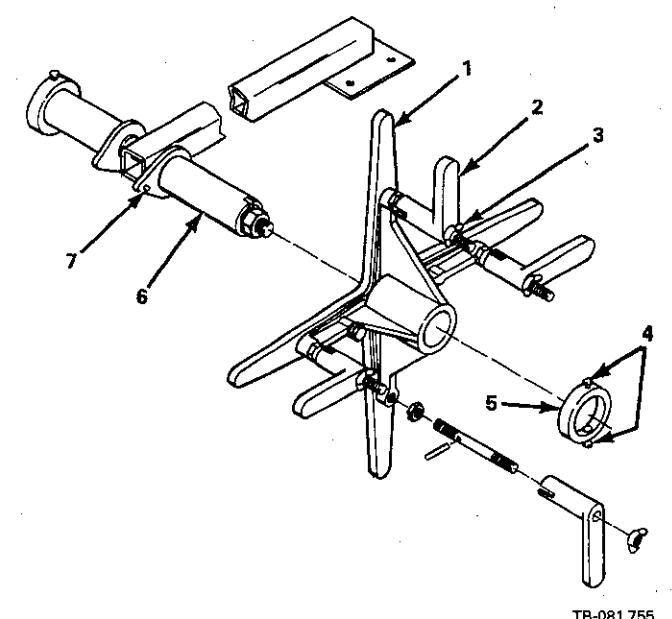
Figure 3-3. Reel Installation
- 1. Remove the retaining ring (5).
- 2. Slide the wire reel (1) onto the hub (6). Rotate the wire reel (1) until the hub guide pin (7) is seated in the reel (1).
- 3. Depress the two spring-loaded stops (4) on the retaining ring (5) and slide the retaining ring (5) into proper position on the hub (6). Release the two stops (4).
3 - 6. DRIVE ROLL AND WIRE GUIDE INSTALLA-TION (Figure 3-4) - Upon initial installation, or as a result of changes in wire size and type, it is necessary to install the required drive rolls and wire guides.

Figure 3-4. Drive Roll Installation
IMPORTANT: Base selection of drive rolls upon the following recommended usages:
1. V-Groove rolls for hard wire.
2. U-Groove rolls for soft and soft shelled cored wires.
3. U-Cog rolls for extremely soft shelled wires (usually hard surfacing types).
4. Split V-Knurled rolls for hard shelled cored wires (self-shielding and CO2 shielded types).
5. Drive roll types may be mixed to suit particular requirements (example: V-knurled roll in combination with U-groove).
Having selected the appropriate drive rolls and wire guides, proceed to the following installation instructions:
A. Drive Roll Installation (Figures 3-4 & 3-5)

TA-081 756
Figure 3-5. U-Cog Drive Rolls Installation
- 1. Loosen pressure adjustment wing nut (item 2, Figure 3-4) and pivot it free of cover.
- 2. Pivot gear cover (4) away to expose pressure gear.
- 3. Loosen and remove the three securing screws (7 & 12) on each gear (5 & 9).
- For one piece drive rolls (8 & 13): Slide a drive roll onto the drive gear (9) and pressure gear (5) with holes aligned and secure with screws (7 & 12).
For split drive rolls (6 & 10): Align holes on each side of split drive rolls, insert a securing screw (7 & 12) and slide a drive roll onto the drive gear (9) and pressure gear (5) with screw in line with one of the threaded holes. Insert remaining screws (7 & 12) and tighten.
IMPORTANT: One-piece drive rolls (8 & 13) are of the double usage type. When the grooves become worn, reverse each drive roll, locating the unused groove in position to feed the wire.
Split drive rolls (6 & 10) are of the double usage type. When the knurled groove of the drive roll becomes worn, the split halves may be reversed so that the unused edges will now provide a new knurled groove.
IMPORTANT: To ensure proper gripping action of U-Cog drive rolls, both rolls should be installed showing slots on the side or both should show the side without slots. Also, it is necessary to line up the blunted teeth on the pressure gear roll directly over the spaces between the teeth on the drive gear roll as illustrated in Figure 3-5.
B. Inlet Wire Guide (Figure 3-4)
-
1. For .030 in. 5/64 in. (0.8-2.0 mm) wire
- a. Insert liner (18) into inlet wire guide (17) and secure with setscrew.
- b. Loosen the inlet wire guide securing screw (3).
IMPORTANT: Wire guides should be installed so that the tip of the guide is as close to the drive roll as possible without touching.
- c. Insert guide assembly into drive assembly. Secure by tightening screw (3)
-
2. For 3/32 in. 1/8 in. (2.4-3.2 mm) wire
- a. Separate anti-wear guide and inlet wire guide.
- b. Insert anti-wear guide (19) into inlet wire guide (1) and secure with setscrew.
- c. Loosen the inlet wire guide securing screw (3).
IMPORTANT: Wire guides should be installed so that the tip of the guide is as close to the drive roll as possible without touching.
d. Insert guide assembly into drive assembly. Secure by tightening screw (3).
IMPORTANT: Drive roll alignment has been factory set, but if readjustment is necessary rotate the drive gear securing bolt (11) thereby moving the drive roll in or out to the desired position. The drive roll on the pressure gear will locate itself on the wire when the gear cover is replaced and the gears mesh together.
3 - 7. WATER CONTROL KIT (Optional) CONNEC-TIONS
CAUTION: OVERHEATING of Gas Metal-Arc Welding (GMAW) gun can damage gun.
If using a water cooled gun and recirculating coolant system, do not make connections from the coolant pump to water valve; instead, make connections directly from the coolant system to gun hoses.
A. Installation Of Water Hoses
Water coolant is supplied to either one gun or both guns utilizing one water solenoid and the same input, output, and return hoses. The solenoid is energized when the POWER switch is placed in the ON position.
Connect a hose from the water supply to the Water input fitting at the rear of the control. This fitting has a left-hand thread. The water supply hose routed through the boom, connects to the Water fitting at the front of the control.
When water is required for one gun only, connect the adapter to the appropriate weld terminal on the drive assembly and connect the water return hose to this adapter. If water is required for both guns, connect the return hose "Y" assembly to an adapter at each weld terminal. The water return hose is routed through the boom. Connect this hose to an appropriate disposal.
B. Electrical Reconnection Of Water Solenoid
The control is shipped connected to supply water when the POWER switch is in the ON position. The water solenoid circuitry can be modified to supply water when the appropriate gun trigger is depressed.
1. Shut unit down and disconnect from line voltage.
WARNING: ELECTRIC SHOCK can kill.
Do not touch live electrical parts.
Disconnect input power to the wire feeder or employ "lockout/tagging procedures" on the welding power source before internally inspecting or servicing.
Lockout/tagging procedures consist of padlocking line disconnect switch in open position, removing fuses from fuse box, or shutting off and red-tagging circuit breaker or other disconnecting device.
Work on internal parts to be performed by qualified persons.
- 2. Remove control box wrapper.
- 3. Locate terminal strip 1T on bottom panel of control.
- 4. Right Side Only: To supply water on the right side when the Right Gun trigger is depressed, move lead No. 6 from terminal A on terminal strip 1T to terminal C.
Left Side Only: To supply water on the left side when the Left Gun Trigger is depressed, move lead No. 6 from terminal A on terminal strip 1T to terminal E.
Either side: To supply water on either side when the appropriate gun trigger is depressed, move lead No. 6 from terminal A on terminal strip 1T to terminal K.
5. Replace wrapper.
3 - 8. WELDING GUN CONNECTIONS
A. Outlet Wire Guides (Figure 3-4)
IMPORTANT: The outlet guide is provided as part of each gun assembly.
1. Loosen the gun/feeder connector securing knob(s) (16).
IMPORTANT: Wire guides should be installed so that the tip of the guide is as close to the drive roll as possible without touching.
- Insert the gun/feeder connector(s) (14) from the gun(s) which includes the installed outlet guide(s), into the drive assembly opposite the respective inlet wire guide(s) as illustrated in Figure 3-4.
- 3. Tighten the gun/feeder connector securing knob(s) (16).
B. Weld Cables (Figure 3-6)
Two holes are provided in the drive assembly for connecting the boom weld cables and the corresponding gun weld cables (see Figure 3-6). Connect the Left Gun weld cable (if so equipped) to the boom weld cable on the left drive assembly using the supplied hardware and the Right Gun weld cable (if so equipped) to the boom weld cable on the right drive assembly.

Figure 3-6. Gun Weld Cable Connections
C. Shielding Gas
The shielding gas hose from each gun is to be connected to the appropriate gas hose which extends out of the motor end of the boom. Connect the gas hose from the Left Gun to the hose labeled LEFT GAS and the gas hose from the Right Gun to the other gas hose.
IMPORTANT: Integral gas input fittings are provided on the drive assembly for guns utilizing this type of connection (see Figure 3-6). If the gas hoses, which extend out of the motor end of the boom, are provided with fittings, cut the fittings off and push the hoses onto the appropriate barbed fittings on the drive assembly. See the appropriate welding gun Owner's Manual for instructions on making this connection.
D. Switch Control
Two four-contact receptacles extend out of the motor end of the boom for connecting the gun switch plugs to the control. Connect the Left Gun to the gun switch receptacle labeled LEFT TRIGGER, and the Right Gun to the other gun switch receptacle by inserting the plugs fully into the receptacles and rotating the locking rings.
WARNING : ELECTRIC SHOCK can kill.
- Do not touch either electrode wire when either gun switch is closed.
- Do not touch live electrical parts.
Welding wire and all metal parts in contact with it carry weld current when the welding power source contactor is energized.
E. Water (If Applicable)
If water coolant is required for one gun only, connect the gun water input hose to the water output hose at the motor end of the boom. (If water is required for both guns, the water output hose from the control divides at the motor end of the boom to accept connections from both gun water input hoses.) Connect the water return hose from the gun to the adapter at the appropriate weld terminal on the drive assembly.
Reducing bushings are provided to accept 5/8-18 L.H. fittings. If the reducing bushings are removed, 7/8-14 L.H. fittings can be accomodated.
3 - 9. SHIELDING GAS CONNECTIONS - A divided-hose assembly is supplied with the unit for making connections to the Shielding Gas input fittings at the rear of the control from one shielding gas source. These fittings have a right-hand thread.
IMPORTANT: If a different shielding gas is required for each welding gun, a separate hose can be connected from each shielding gas source to the appropriate input fitting at the control.
The gas hoses, routed through the boom, connect to the appropriate Shielding Gas output fittings at the front of the control.
3-10. BOOM ADJUSTMENTS (Figure 3-7)

Figure 3-7. Boom Adjustments
A. Weight Lift Adjustment
WARNING: FALLING BOOM can cause serious personal injury and equipment damage.
Maintain full threads on adjustment rod through the yoke.
The amount of weight which the boom can retract into the upright position when released can be varied by adjusting the jam nut and adjustment rod located at the base of the boom. If heavier guns are installed on the end of the boom thereby making it necessary to increase the amount of weight that the boom can lift, loosen the jam nut and rotate the adjustment rod so that the adjustment rod threads into the yoke. When the proper adjustment is obtained, tighten the jam nut against the base of the yoke. If lighter guns are used with the Swingarc, rotate the adjustment rod so that the adjustment rod threads out of the yoke.
B. Locking Knob
By rotating the Locking Knob, located on the side of the swivel plate, in a clockwise direction, the boom may be held in any desired position. Rotating the Locking Knob in a counterclockwise direction will permit the boom to free travel. Changing the position of the Locking Knob to the other threaded holes provided along the side of the swivel plate, limits the lift of the boom to 50 degrees or 40 degrees respectively during free travel.
3-11. MOTOR CONTROL CONNECTION (Figure 3-8)
A receptacle is provided for connecting the motor control plug to the control. Align keyways and insert the plug from the control end of the boom into the receptacle and rotate the plug threaded collar clockwise as far as possible.

Figure 3-8. Rear Panel Connections
3-12. GUN TRIGGER CONNECTIONS (Figure 4-1) – Two receptacles, labeled TRIGGER, are provided on the front panel of the control for making gun trigger control connections. The gun trigger control cables extend out of the control end of the boom. Insert the gun
trigger control plug, labeled LEFT TRIGGER, into the gun trigger control receptacle on the Left control and the other gun trigger control plug into the receptacle on the Right control and rotate the threaded collars clockwise.
3-13. WELD CABLE CONNECTION - Two weld cables extend out of the control end of the boom for making secondary connections to the welding power sources. The end of each weld cable is equipped with a terminal for a 1/2 in. (12.7 mm) stud. Connect weld cables to the desired POSITIVE output terminal on the applicable welding power source.
IMPORTANT: If one welding power source is used, connect the weld cables from the wire feeder to the welding power source High or Low POSITIVE output terminal as desired.
3-14. INSTALLATION OF SPOOL-TYPE WIRE (Figure 3-2)
- 1. Remove the retaining ring (12).
- 2. Slide the spool of wire onto the hub (4) so that the wire will feed off the top of the spool. The spool turns in a clockwise direction.
- 3. Rotate the spool until the hole in the spool aligns with the pin in the hub (4). Slide the spool onto the hub until it seats against the back flange of the hub.
- Depress the two spring-loaded stops (11) on the retaining ring (12) and slide the retaining ring (12) into proper position on the hub (4). Release the two stops (11).
3-15. INSTALLATION OF REEL-TYPE WIRE (Figure 3-3)
- 1. Loosen the four wing nuts (3) on the fingers (2) of the wire reel (1).
- 2. Pull the four fingers (2) out until they can be rotated toward the center of the reel (1).
- 3. Install the wire onto the reel (1) over the four fingers (2). Ensure that the wire feeds off the top of the reel (1). The reel (1) turns in a clockwise direction.
- 4. Rotate the four fingers (2) back to their proper position. Tighten the four wing nuts (3).
3-16. ADJUSTMENT OF HUB TENSION (Figure 3-2) – Check the hub tension by slowly pulling the wire toward the feed roll. The wire should unwind freely, but the hub tension should be sufficient to keep the wire taut and prevent backlash when the wire feeding ceases. If adjustment is required, loosen or tighten the hex nut (10) on the end of the spindle support shaft (1) accordingly.
3-17. REMOTE CONTROL CONNECTIONS (Figure 4-1) – Left and Right Remote Control receptacles are provided for connecting remote or optional equipment
to the control/feeder. Align keyways and insert the plug from the remote or optional equipment into the appropriate remote control receptacle and rotate the threaded collar clockwise as far as possible.
3-18. CONTACTOR CONTROL CONNECTIONS (Figure 3-8)
CAULION: IMPROPER VOLTAGE APPLIED TO WELDING POWER SOURCE CONTACTOR can damage wire feeder and welding power source.
Ensure welding power source contactor control circuitry requires external supply of 115 vac for contactor control.
Wire feeder supplies 115 volts ac to the welding power source for contactor control.
A. Using One Welding Power Source
The contactor control circuitry in this wire feeder is connected to operate both guns from one welding power source.
Insert the plug on one contactor control cable fully into the Left Contactor Control receptacle and rotate the plug clockwise. Connect the remaining end of the contactor control cable to the contactor control receptacle on the welding power source. Store the remaining contactor control cable.
WARNING ELECTRIC SHOCK can kill.
- Do not touch either electrode wire when either gun switch is closed.
- Do not touch live electrical parts.
Welding wire and all metal parts in contact with it carry weld current when the welding power source contactor is energized.
B. Using Two Welding Power Sources
Through minor modification, the contactor control circuitry of the wire feeder can be adapted to operate two welding power sources, that is, the left gun switch governing contactor control to one welding power source and the right gun switch governing contactor control to the other. Two contactor control cables are supplied with the unit for making connections to the contactor control circuitries in the welding power sources.
WARNING ELECTRIC SHOCK can kill.
- Do not touch live electrical parts.
- Disconnect input power to the wire feeder or employ "lockout/tagging procedures" on the welding power source before internally inspecting or servicing.
Lockout/tagging procedures consist of padlocking line disconnect switch in open position, removing fuses
from fuse box, or shutting off and red-tagging circuit breaker or other disconnecting device.
Work on internal parts to be performed by qualified persons.
- 1. Remove the wrapper from the control box.
- 2. Locate terminal strip 1T on the bottom panel of the control.
- 3. Disconnect lead No. 39 from terminal K on terminal strip 1T and reconnect it to terminal E.
- 4. Replace wrapper.
- 5. Align keyways and insert the contactor control plug into the Right Contactor Control receptacle and rotate the threaded collar clockwise. Insert contactor plug into the right welding power source contactor control receptacle and rotate clockwise.
- Align keyways and insert the 115 volts/contactor control plug into the Left 115 Volts/Contactor Control receptacle and rotate threaded collar clockwise. Insert the 115 volts power plug into the 115 volts ac receptacle on the welding power source and rotate clockwise. Insert contactor control plug into the welding power source contactor control plug into the welding power source contactor control receptacle and rotate clockwise.
3-19. PULLEY ADJUSTMENT (Figure 3-6)
WARNING ELECTRIC SHOCK can kill.
- Do not touch live electrical parts. Shut down the wolding
- Shut down the welding power source and wire feeder and be sure that they cannot be accidentally energized before adjusting pulley(s).
The boom pulleys can be adjusted up or down to provide the minimum bend in the wire. For small diameter wires (0.030-5/64 in. or 0.8-2.0 mm), have pulley shaft in upper holes. For larger diameter wires (3/32-1/8 in. or 2.4 to 3.2 mm), have pulley shaft in lower holes. If a pulley adjustment is necessary because of a wire size change, proceed as follows:
- 1. Retract wire and change to new wire size.
- 2. Loosen nuts securing pulley shaft to boom.
- 3. Move shaft to desired hole: Upper hole for fine diameter wires, lower hole for larger diameter wires.
- 4. Tighten nuts to secure pulley shaft.
- 5. Thread welding wire according to Section 5-1.

Figure 4-1. Control Components
4 – 1. POWER SWITCH (Figure 4-1) – Placing the POWER switch in the ON position will apply 115 volts ac to the unit and place it in an operational condition, ready to feed wire and permit shielding gas to flow from either gun. Placing the POWER switch in the OFF position will shut the wire feeder down.
4 – 2. WIRE SPEED CONTROLS (Figure 4-1) – The WIRE SPEED controls provide the means of determining the rate at which welding wire is fed into the weld. Rotating the LEFT WIRE SPEED control clockwise increases the rate at which wire is fed from the Left Gun. Rotating the RIGHT WIRE SPEED control clockwise increases the rate at which wire is fed from the Right Gun.
The scales surrounding the WIRE SPEED controls are calibrated in increments of ten ranging from 0 to 100 percent. When these scales are used to select the wire feed speed settings, only a percentage of the range in use is selected and not an actual wire feed speed rate. When a WIRE SPEED control is set at 0, wire feeds at the slowest speed; when set at 100, the wire feeds at the fastest speed.
4 - 3. REMOTE CONTROL RECEPTACLES AND SWITCHES (Figure 4-1) – The Remote Control receptacles and switches are provided for use in conjunction with certain optional controls. When an optional control is connected across a Remote Control receptacle, the corresponding switch must be in the REMOTE position. If no optional controls are used, the Remote Control switches must be in the STANDARD position.
4 – 4 . PURGE BUTTONS (Figure 4-1) – The PURGE buttons are momentary contact switches. The Left PURGE button energizes the Left Gas Solenoid and purges the shielding gas line of the Left Gun. The Right PURGE button energizes the Right Gas Solenoid and
purges the shielding gas line of the Right Gun. The PURGE buttons also allow the shielding gas regulator(s) to be adjusted without energizing the welding circuit.
4 - 5. JOG SWITCHES (Figure 4-1) - The JOG switches are spring-loaded toggle switches. When activated, either switch completes the circuit to the motor without having to depress the corresponding gun trigger switch. The Left JOG switch permits feeding of the Left wire at the LEFT WIRE SPEED control setting, and the RIGHT JOG switch permits feeding of the right wire at the RIGHT WIRE SPEED control setting without energizing the welding circuits or the corresponding shielding gas valves.
4 - 6. RESET CIRCUIT BREAKER (Figure 4-1) - A circuit breaker provides protection to the feeder motor. In the event the motor should be placed in an overload condition, the breaker would trip and suspend all output. Should this breaker trip, the RESET button would have to be manually depressed to reset the circuit breaker.
4 - 7. BURNBACK CONTROLS (Optional) - The burnback circuitries in this control provide a means of keeping the welding wires from sticking to the workpiece after the corresponding gun switches are released. The Left BURNBACK control keeps weld current present on the left welding wire and the Right BURNBACK control keeps weld current present on the right welding wire from 0 to 15 cycles after the corresponding wire has stopped feeding. This delay action permits the welding wires to burn back to a point where they neither stick to the workpiece nor the contact tubes. If welding wire sticks to the contact tube, rotate the corresponding BURNBACK control counterclockwise. If welding wire sticks to the workpiece, rotate the corresponding BURNBACK control clockwise
5 - 1. WELDING WIRE THREADING
WARNING : ELECTRIC SHOCK can kill.
- Do not energize welding power source or wire feeder until instructed to do so.
- Do not touch live electrical parts.
Welding wire and all metal parts in contact with it carry weld current when the welding power source contactor is energized.
CAUTION: WELDING WIRE can cause puncture wounds; HOT SURFACES can burn skin.
- Do not activate gun trigger until instructed to do so.
- Do not point gun toward any part of the body or other personnel when threading welding wire.
-
Allow gun to cool before touching.
- 1. Install the wire (reel-type or spool-type) as instructed in Section 3-14 or 3-15 on the desired side.
- 2. Cut off any portion of the free end of the wire which is not straight. Ensure that the cut end is free from rough surfaces to permit proper feeding.
- 3. Route the wire through the wire guide tube on the side of the boom, over the wire pulley, and to the drive assembly.
- 4. If necessary because of wire size change, adjust boom pulley(s) for minimum wire bend according to Section 3-19.
- 5. Loosen the wing nut on the drive roll pressure adjustment, pivot the pressure adjustment free of the cover, and pivot the pressure gear assembly away until it is in an open position.
- Feed the wire through the inlet wire guide, past the drive rolls, and on into the outlet wire guide. Feed approximately 4 inches (102 mm) of wire into the outlet wire guide.
IMPORTANT: If when the gear cover is closed, the U-Cog drive rolls are not aligned properly (see Section 3-6), pivot the gear cover away from the drive gear and rotate the pressure gear one tooth.
- 7. Pivot the gear cover closed making sure the teeth on the pressure gear mesh with the teeth on the drive gear. The welding wire must also be in the grooves of the drive rolls.
- 8. Pivot the pressure adjustment wing nut until the washer on the pressure adjustment is seated on top of the gear cover.
- 9. Turn the pressure adjustment wing nut in a clockwise direction until the drive rolls are tight against the welding wire. Do not overtighten. Further adjustment to attain desired clamping pressure can be made after the welding power source and the wire feeder are put into operation.
- 10. Draw the gun cable out straight.
- 11. Repeat Steps 1-10 on the opposite side,
- 12. Energize the welding power source.
- 13. Place the control POWER switch in the ON position.
- 14. Depress the Left JOG switch. This will run the welding wire through the Left Gun without placing weld current on the wire. Release the Left JOG switch when welding wire extends approximately one inch (25.4 mm) out of the gun tip.
- 15. Depress the Right JOG switch until welding wire extends approximately one inch (25.4 mm) out of the Right Gun tip. Weld current will not be present on the wire.
WARNING: ARC RAYS, SPARKS, AND HOT SURFACES can burn eyes and skin; NOISE can damage hearing.
• Wear correct eye, ear, and body protection.
FUMES AND GASES can seriously harm your health.
• Use enough ventilation to keep fumes and gases from the breathing zone.
See Section 1 - Safety Rules For Operation Of Arc Welding Power Source for basic welding safety information.
5 - 2. GAS METAL-ARC WELDING (GMAW)
- 1. Make all necessary connections as instructed in Section 3 of this manual.
- 2. Rotate the WIRE SPEED controls to the desired settings.
- 3. If a remote control is to be used on either or both sides, make connection to the appropriate Remote Control receptacle(s) and place the corresponding Remote Control switch(s) in the REMOTE position. If no remote controls are used, place both Remote Control switches in the STANDARD position.
- 4. Place the POWER switch on the control in the ON position.
- 5. Energize the welding power source(s).
- 6. Turn on the shielding gas at the source(s).
- 7. Depress the PURGE buttons for one minute.
- 8. Hold the tip of the desired gun approximately 1/2 inch (12.7 mm) from the workpiece.
- 9. Depress the trigger on the gun handle. Gas will start to flow and wire will start to feed if drive roll pressure is properly adjusted to prevent slippage. If wire slippage is noticed, tighten the drive roll pressure adjustment wing nut 1/2 turn clockwise. Repeat until slippage stops. Do not overtighten wing nut.
WARNING ELECTRIC SHOCK can kill.
- Do not touch welding wire or any metal part in contact with it while welding.
- Do not touch live electrical parts.
Welding wire and all metal parts in contact with it carry weld current when the welding power source contactor is energized.
5 - 3. SHUTTING DOWN
IMPORTANCE Periodically inspect the labels on the unit for legibility. All precautionary labels must be maintained in a clearly readable state and replaced when necessary. See Parts List for part number of precautionary labels.
6 - 1. INSPECTION AND UPKEEP - Usage and shop conditions will determine the frequency and type of maintenance. Inspect equipment as follows:
WARNINGS ELECTRIC SHOCK can kill; WELDING WIRE can cause puncture wounds; HOT SURFACES can burn skin.
- Disconnect unit from input power before internally inspecting or servicing.
- Allow gun and unit to cool before touching.
-
Do not activate gun trigger while performing maintenance on gun.
- 1. Make sure welding power source is shut down.
- 2. Inspect gun for broken areas, cracks and loose parts: tighten, repair, and replace as required.
- 3. Carefully remove any weld spatter or foreign matter which may accumulate around the nozzle orifice. Use a hardwood stick, never a metal tool.
- 4. Repair or replace, as required, all hose and cable; give particular attention to frayed and cracked insulation and areas where it enters equipment.
- 5. Remove grease and grime from components; moisture from electrical parts and cable.
- 6. Blow out the gun wire guide liner with compressed air when changing wire. This will remove any metal chips and dirt that may have accumulated.
6 – 2. CLEANING OF DRIVE ROLLS – Occasionally it will become necessary to clean the wire groove on the drive rolls. This cleaning operation can be performed with a wire brush.
To clean the wire grooves it will be necessary to disconnect the unit from input power before removing drive roll(s) (see Section 3-6 for removal and installation instruction).
IMPORTANTE Failure to properly maintain the drive rolls can result in a buildup of wire particles which will decrease the efficiency of the wire feeding operation.
- 1. Turn off the shielding gas at the source(s).
- 2. Place the POWER switch on the control in the OFF position.
- 3. Turn off all associated equipment.
MARNINGE HIGH CONCENTRATION OF SHIELDING GASES can harm health or kill.
Shut off gas supply when not in use.
SECTION 6 - MAINTENANCE
6 - 3. FUSE (Figure 4-1) – The control is protected from damage due to an internal short or excessive overload by fuse F1. Should F1 open, the control would be completely inoperative.
6 - 4. BRUSH INSPECTION & REPLACEMENT (Figures 6-1 & 6-2)
1. Shut off unit and associated equipment.
WARNING ELECTRIC SHOCK can kill.
- Do not touch live electrical parts.
- Disconnect input power to the wire feeder or employ "lockout/tagging procedures" on welding power source before internally inspecting or servicing.
Lockout/tagging procedures consist of padlocking line disconnect switch in open position, removing fuses from fuse box, or shutting off and red-tagging circuit breaker or other disconnecting device.
Work on internal parts to be performed by qualified persons.

TA-046 226
Figure 6-1. View Of Spring Assembly And Brush When Brush Cap Is Opened
- 2. Open brush cap by sliding screwdriver under catch and lifting. Remove brush cap.
- 3. Grasp spring retaining bracket with long-nose pliers.
- 4. Push spring retaining bracket in lightly and move towards brush. This should release the spring assembly and it can be removed.
- 5. Pull brush out using brush pigtail.
- 6. If the brushes are less than 1/4 in. (6.4 mm) long, replacement is necessary. Disconnect the brush pigtail from the brush box tab and remove brush.

SECTION 7 - TROUBLESHOOTING
Figure 6-2. View Of Spring Assembly And Brush From Armature End Of Motor
- 7. Connect new brush pigtail to brush box tab.
- 8. Route pigtail through slot in brush box. Ensure that the pigtail will not come into contact with a metal surface.
WARNING: ELECTRIC SHOCK can kill.
- Do not touch live electrical parts.
- Disconnect unit from input power before internally inspecting or servicing.
Troubleshooting of internal parts to be performed only by qualified persons.
7 - 1. GENERAL - It is assumed that proper installation has been made, according to Section 3 of this manual, and that the unit has been functioning properly until this trouble developed.
7 - 2. TROUBLESHOOTING CHART - The following chart is designed to diagnose and provide remedies for some of the troubles that may develop on this unit.
Use this chart in conjunction with the circuit diagram while performing troubleshooting procedures. If the
- 9. Insert brush into brush box. Ensure that the low end of the bevel on the top of the brush is towards the spring.
- 10. Using long-nose pliers, insert spring assembly beside brush sliding the spring retaining bracket along the brush box wall. The spring retaining bracket hooks on the brush box wall as illustrated in Figure 6-2.
- 11. If the spring retaining bracket is in place, it will lie flat against the brush box wall when the pliers are released.
- 12. Ensure that the spring is in the proper position as illustrated in Figure 6-1
- 13. Replace and latch the brush cap.
- 14. Reconnect power to all equipment and resume operation
trouble is not remedied after performing these procedures, the nearest Factory Authorized Service Station should be contacted. In all cases of equipment malfunction, the manufacturer's recommendations should be strictly followed.
CAUTIONE DISASSEMBLY OF MOTOR FIELD MAGNETS can result in personal injury or equipment damage.
• Limit wire drive motor repairs to brush replacement.
The field magnets are very strong. If disassembly is attempted, injury to fingers and hands may result from a magnet being drawn back into the motor. The field magnets are matched sets and operation may be affected if the magnets are tampered with. Warranty is void if the motor is tampered with
| TROUBLE | PROBABLE CAUSE | SUGGESTED CHECK AND/OR REMEDY | ||
|---|---|---|---|---|
| Depressing gun switch will | ON-OFF POWER switch in | Place switch to ON position. | ||
|
not energize wire feeder.
Electrode wire is not |
tive. | Replace defective POWER switch. | ||
| energized and shielding gas does not flow, | 115 volts input fuse F1 open. | *Replace fuse F1. | ||
| 115 volts ac input plug is not secure in receptacle. | Insert plug fully into 115 vac receptacle and rotate plug 1/2 turn clockwise. | |||
| Plug from gun switch is not secure in trigger cable. |
Insert plug fully into trigger cable and rotate lock-
ing ring. |
|||
|
Plug from cable is not secure in TRIGGER recep-
tacle. |
Insert plug fully into TRIGGER receptacle and rotate plug 1/2 turn clockwise. | |||
| Circuit breaker CB1 tripped. | Manually reset circuit breaker by depressing the button on the front panel of the control labeled RESET. | |||
|
Wire feeds, shielding gas
flows, but electrode wire is not energized. |
115 Volts/Left Contactor
Control plug is not secure in contactor receptacle on welding power source. |
Insert plug fully into receptacle and rotate plug 1/2 turn clockwise. | ||
| Contactor Control cable leads not secure on contactor plug terminals. | Secure leads to plug terminals. | |||
| Defect in welding power source. | See TROUBLESHOOTING Section in welding power source instruction manual. | |||
| Wire feeds erratically. |
Pressure on drive rolls is in-
sufficient. |
Rotate pressure adjustment wing nuts clockwise in 1/4 turn increments until wire slippage stops. | ||
| Drive roll is too large for wire size being used. | Change to proper size drive roll. See Section 3-6. | |||
| Worn drive roll. | Replace drive roll. See Section 3-6. | |||
| Dirt in drive roil. | Clean drive roll as instructed in Section 6-2. | |||
*If it becomes necessary to replace any fuse in the wire feeder, ensure that a fuse of the proper rating, type, and size is used.

Figure 7-1. Circuit Diagram
February 1982 FORM: OM-1517B
Effective With Serial No. JB502167
MODEL SWINGARC DUAL 12 SWINGARC DUAL 16

PARTS LIST

Figure A - Main Assembly
|
Quantity
Model |
|||||
|---|---|---|---|---|---|
| Item | Dia. | Part | |||
| No. | Mkgs. | No. | Description | 12 | 16 |
| Figu | re A | Main Assembly | |||
| 1 | 081 964 | CORD, control - interconnecting (consisting of) | 1 | 1 | |
| 2 | PLG3 | 039 635 | . CONNECTOR BODY, twistlock 2P2W | 1 | 1 |
| 3 | PLG8 | 039 687 | . CAP, twistlock - grounded 2P3W 15 amp 2/7 volts | 10 8 | 10 4 |
| 4 | 604 571 | . CORD, No. 18 4/c (order by ft) | 1011 | ||
| 5 | D1 07 | 079 531 | 1 | 1 | |
| 6 | PLG/ | 048 284 | TEDMINAL female | 4 | 4 |
| 7 | 0/9 534 | CORD No. 19.2/c (order by ft) | 2 ft | 2 ft | |
| / | 049 400 | HOSE ASSEMBLY are (consisting of) | 1 | 1 | |
| 0 | 056 951 | EITTING hose - barbed pipple 3/16 TBG | 3 | 3 | |
| 10 | 010 606 | FITTING, hose - put 5/8-18 BH | 3 | 3 | |
| 11 | 056 112 | FITTING, hose - ferrule 0.475 ID x 23/32 | 6 | 6 | |
| 12 | 604 550 | HOSE neoprene - braided No. 1 x 3/16 ID (order by ft) | 11 ft | 11 ft | |
| 13 | 073 433 | FITTING, barbed - male 3/16 TBG x 1/4 NPT | 2 | 2 | |
| 14 | 044 858 | FITTING, pipe - Y short 1/8 NPT x 1/4 NPT | 1 | 1 | |
| 15 | 073 432 | FITTING, barbed - male 3/16 TBG x 1/8 NPT | 1 | 1 | |
| 16 | 051 297 | . ADAPTER | 1 | 1 | |
| 17 | 047 684 | CORD, trigger - left 16 ft. (consisting of) | 1 | ||
| 17 | 047 685 | CORD, trigger - left 20 ft. (consisting of) | 1 | ||
| 18 | 049 012 | CORD, trigger - right 16 ft (consisting of) | 1 | ||
| 18 | 048 618 | CORD, trigger - right 20 ft (consisting of) | 1 | ||
| 19 | 605 156 | . CORD, portable No. 18 4/c (order by ft) | 16 ft | 20 ft | |
| 20 | 079 531 | . CLAMP, cable | 2 | 2 | |
| 21 | PLG2,13 | 079 878 | . HOUSING PLUG & PINS (consisting of) | 1 | 1 |
| 079 535 | TERMINAL, male | 4 | 4 | ||
| 22 | PLG14,15 | 080 328 | . RECEPTACLE W/SOCKETS, free - hanging (consisting of) | 1 | 1 |
| 23 | 079 534 | TERMINAL, female | 2 | 2 | |
| 24 | 079 202 | HOSE, gas 15 ft 9 inches right (consisting of) | 1 | ||
| 24 | · | 079 204 | HOSE, gas 19 ft right (consisting of) | 1 | |
| 25 | 003 160 | HOSE, gas 15 ft 9 inches left (consisting of) | 1 | ||
| 25 | 003 159 | HOSE, gas 19 ft left (consisting of) | 40 51 | 1 | |
| 26 | 604 550 | , HOSE, No. 1 x 3/16 ID (order by ft) | ιοπ | 19 π | |
| 27 | 056 108 | . FITTING, hose - ferrule 0.425 ID x 23/32 | 4 | 2 | |
| 28 | 010 606 | , FITTING, hose - nut 5/8-16 |
.).
|
1 | |
| 29 | 056 851 | FITTING, hose - barbed hipple 3/16 TBG | 1 | 1 | |
| 30 | 010 604 | . FIT ING, hose - busning 1/4 NPT X 5/8-18 Rm | 1 | 1 | |
| 31 | 079 196 | - FILLING, Darbed - remaie 3/16 TBG X 1/4 NPT | 1 | 1 | |
| 32 | a. | 072 095 | 1 | ||
| 33 | 072 103 | CORD, motor 19 ft 6 inches (consisting of) | • | 1 | |
| 33 | 072 102 | TERMINAL ring tongue. No. 10 stud | 3 | 3 | |
| 34 | DI C1(M) | 049 206 | PECEPTACIES PINS (consisting of) | 1 | 1 |
| 35 | PLGT(W) | 040 300 | 6 | 6 | |
| 26 | 079 535 | 1 | 1 | ||
|
30
77 |
· | 073 700 | COBD_portable No. 18 3/c (order by ft) | 17 ft | 21 ft |
|
3/
20 |
007 020 | COBD power 27 ft left (consisting of) | 1 | ||
| 20 | 080 940 | CORD, power 30 ft left (consisting of) | 1 | ||
| 30 | 078 992 | CORD, power 27 ft right (consisting of) | 1 | ||
| 20 | 078 993 | CORD, power 30 ft right (consisting of) | 1 | ||
| 40 | 077 455 | TERMINAL, ring tongue 1/2 No. 3/0 wire | 1 | _ 1 | |
| 41 | 600 323 | . CABLE, weld - copper No. 3/0 (order by ft) | 24 ft | 28 ft | |
| 12 | 600 742 | TERMINAL ring topque 3/8 stud No. 3/0 wire | 1 | . 1 | |
| Quantity | ||||||
|---|---|---|---|---|---|---|
| ltem | Dia. | Part | Μ | lodel | ||
| No. | Mkgs. | No. | Description | 12 | 16 | |
| Figur | e A | Main Assembly (Cont'd) | ||||
| 43 | 080 947 | BRACKET, spring - retaining | 1 | 1 | ||
| 44 | Figure D | BOOM (Pg 10) | 1 | 1 | ||
| 45 | 1079 591 | BASE, 4 ft or | 1 | |||
| 45 | 1079 214 | BASE, 6 ft | 1 | : | ||
| 45 | †078 264 | BASE, 4 ft or | 1 | |||
| 45 | t079 216 | BASE, 6 ft | ່ 1 | |||
| 46 | 1075 390 | POST, support - boom 4 ft (consisting of) or | 1 | |||
| 46 | †079 215 | POST, support - boom 6 ft (consisting of) | 1 | |||
| 46 | , †075 078 | POST, support - boom 4 ft (consisting of) or | 1 | |||
| 46 | 1 | t079 217 | POST, support - boom 6 ft (consisting of) | 1 | ||
| 47 | 080 157 | . FITTING, grease 1/8 NPT | 1 | 1 | ||
| 48 | 080 408 | GEAR, spur - steel 33 tooth 1/2 bore keyed | 1 | 1 | ||
| 49 | 080 412 | GUARD, motor - gear | 1 | 1 | ||
| 50 | 080 419 | SPACER, 1 OD x 17/32 ID x 1/4 thick | 1 | 1 | ||
| 51 | 080 416 | INSULATOR, housing | 1 | 1 | ||
| 52 | Figure B | WIRE DRIVE & GEARS (Pg 4) (consisting of) | 2 | 2 | ||
| 53 | 079 633 | . FITTING, hose - corded nipple 3/16 TBG | 1 | 1 | ||
| 54 | 072 010 | BUSHING, 0.316 ID x 7/16 x 13/16 x 3/16 | 4 | 4 | ||
| 55 | 080 409 | SHAFT, drive - clutch | 2 | 2 | ||
| 56 | 080 411 | GUARD, drive - gear | 1 | 1 | ||
| 57 | 080 404 | GEAR, spur - drive | 1. | 1 | ||
| 58 | 010 910 | WASHER, flat - SAE 3/8 | 4 | 4 | ||
| 59 | 602 213 | WASHER, lock - split 3/8 | 4 | 4 | ||
| 60 | 601 965 | SCREW, cap - hex hd 3/8-16 x 1 | 2 | 2 | ||
| 61 | 601 872 | NUT, hex - full 3/8-16 | 2 | 2 | ||
| 62 | 080 417 | INSULATOR, housing | . 1 | 1 | ||
| 63 | 015 713 | GROMMET, rubber 5/16 ID x 1/2 mounting hole 3/16 groove | 1 | 1 | ||
| 64 | 080 802 | MOTOR, gear 1/8 hp 115 volts dc 2000 rpm (consisting of) | 1 | . 1 | ||
| 080 283 | . COVER, brush | 2 | 2 | |||
| 080 282 | . SPRING, brush | 2 | 2 | |||
| *080 281 | .BRUSH | 2 | 2 | |||
| 65 | 056 068 | KEY, 1/8 x 1/8 x 1/2 | 1 | 1 | ||
| 66 | 046 174 | CORD, contactor (consisting of) | 1 | 1 | ||
| 67 | PLG8 | 079 878 | . HOUSING PLUG & PINS (consisting of) | 1 | 1 | |
| 079 535 | TERMINAL, male | 4 | 4 | |||
| 68 | 079 531 | . CLAMP, cable | 1 | 1 | ||
| 69 | 049 455 | . CORD, No. 18 2/c (order by ft) | 10 ft | 10 ft | ||
| 70 | PLG3 | 039 635 | . CONNECTOR BODY, twistlock 2P2W 20 amp 250 volts | 1 | 1 | |
*Recommended Spare Parts. †Parts For Optional Equipment. BE SURE TO PROVIDE MODEL AND SERIAL NUMBERS WHEN ORDERING REPLACEMENT PARTS.
| ltem | Part |
|---|---|
| No | No |
Figure B Wire Drive & Gears (Fig A Pg 3 Item 52)
| 1 | 082 036 | GUIDE, inlet wire | 1 |
| 2 | 082 050 | LINER, monocoil - inlet wire | 1 |
| 3 | 604 612 | SCREW, set - socket hd 8-32 x 1/8 | 1 |
| 4 | 045 233 | GUIDE, anti - wear | 1 |
| 5 | 081 801 | WIRE DRIVE (consisting of) | 1 |
| 6 | 604 590 | . NUT, wing 3/8-16 | 1 |
| 7 | 010 910 | . WASHER, flat - SAE 3/8 | 1 |
| 8 | 010 231 | . SPRING, compression | 1 |
| 9 | 056 306 | . FASTENER, pinned | 1 |
| 10 | 602 243 | . WASHER, flat 3/8 | 1 |
| 11 | 010 232 | . SPRING, compression | 1 |
| 12 | 010 224 | . PIN, spring - compression 3/16 x 1 | 1 |
| 13 | 601 925 | . SCREW, cap - hex hd 1/4-20 x 1/2 | 1 |
| 14 | 604 741 | . PIN, cotter - hair 0.042 x 15/16 | 2 |
| 15 | 079 669 | . LEVER, mounting - pressure gear | 1 |
| 16 | 079 634 | . PIN, hinge | 1 |
| 17 | 080 413 | . RETAINER, bearing | 1 |
| 18 | 079 772 | , KNOB, plastic | 1 |
| 19 | 604 538 | . WASHER, flat - SAE 5/16 (as req'd.) | 1 |
| 20 | 080 403 | . HOUSING, adapter - gun/feeder | 1 |
| 21 | 028 342 | . BEARING, ball | 1 |
| 22 | 053 842 | GEAR, spur - insulated w/bearing | 1 |
| 23 | 605 518 | SCREW, cap - hex hd 1/4-20 x 1-1/4 | 1 |
| 24 | 079 626 | SCREW, machine - fillister hd 10-32 x 7/8 | 6 |
| 25 | 010 193 | TUBING, steel 3/8 OD x 18 ga wall x 1/4 | 1 |
| 26 | 048 336 | COVER, stop | 1 |
| 27 | 602 241 | WASHER, flat - SAE 1/4 | 1 |
| 28 | 000 418 | SCREW, cap - hex hd 1/2-20 x 1/2 self - locking | 1 |
| 29 | 053 841 | GEAR, spur - insulating w/key | 1 |
| 30 | 079 625 | WASHER, spring - steel 5/16 shakeproof | 2 |
| 31 | 080 410 | GUARD, drive roll | 1 |

Figure B - Wire Drive & Gears
BE SURE TO PROVIDE MODEL AND SERIAL NUMBERS WHEN ORDERING REPLACEMENT PARTS.
TC-081 523-B

Figure C - Control Box
|
ltem
No. |
Dia.
Mkgs. |
Part
No. |
Description | Quantity |
|---|---|---|---|---|
| Figu | re C | 072 095 | Control Box (Fig A Pg 2 Item 32) | |
| 1 | 047 101 | WRAPPER | 1 | |
| 2 | S2,4 | 011 043 | SWITCH, toggle DPDT mc 6 amp 125 volts. | 2 |
| 3 | PB1,2 | 011 232 | SWITCH, push button SPDT | 2 |
| 4 | , | 080 153 | BRACKET, mounting - relays | 1 |
| 5 | 081 148 | SOCKET, relay 11 pin | 4 | |
| 6 | CR1,2,3,5 | 080 388 | RELAY, enclosed 24 voits ac 3PDT | 4 |
| 7 | 601 219 | LINK, jumper - terminal block 20 amp | 3 | |
| 8 | 1T | 038 782 | BLOCK, terminal 20 amp 10 pole | 1 |
| 9 | RC7 | 048 283 | RECEPTACLE W/PINS (consisting of) | 1 |
| 079 535 | . TERMINAL, male | 4 | ||
| 10 | RC4,10 | 056 266 | CONNECTOR, female 6 contact 7.5 amp | 2 |
| 11 | ** | 604 311 | GROMMET, rubber 1/4 ID x 3/8 mounting hole | 1 |
| 12 | 079 683 | HEAT SINK, resistor | 1 | |
| 13 | 010 193 | TUBING, 3/8 OD x 18 ga wall x 1/4 | 6 | |
| 14 | • | 010 199 | TUBING, 0.275 ID x 0.048 wall x 1 | 2 |
| 15 | 030 949 | HEAT SINK, rectifier | 1 | |
| 16 | 056 170 | SHIELD, rectifier | 1 | |
| 17 | R2 | 030 941 | RESISTOR, WW fixed 100 watt 5 ohm. | 1 |
| 18 | PLG1(F) | 048 380 | HOUSING PLUG & SOCKETS (consisting of) | 1 |
| 079 534 | . TERMINAL, female | 6 | ||
| 19 | 079 706 | CLAMP, cable | 1 | |
| 20 | 007 826 | CORD, portable No. 18 3/c (order by ft) | 4 ft | |
| 21 | 010 476 | BUSHING, strain relief 5/8 x 0.57 hole | 1 | |
| 22 | CR4 | 034 841 | RELAY, 24 volts ac DPDT | 1 |
| 23 | SR1 | 035 914 | RECTIFIER, integrated 30 amp 400 volts | 1 |
| VR1 | 082 722 | VARISTOR, 0.6W 1/5 volts dc | 1 | |
| 24 | 047 123 | S1AND-OFF, 4-40 x 2-5/8 | 1 | |
| 25 | RC2,9,13 | 048 282 | RECEPTACLE W/SUCKETS (consisting of) | 3 |
| ~~ | 079 534 | 4 | ||
| 26 | 057 314 | 1 | ||
| 27 | DAE | 1 | ||
| 28 | RUD | 039 750 | STAND OFE # 40 x 5/8 x 1/4 box | 2 |
| 29 | DIA | 009 335 | BESISTOR option 0 5 worth 2000 obm | 1 |
| 21 | 050 340 | CONNECTOR male 6 contact 10 amp 730 RMS | 2 | |
| 21 | PLG4,10 | 000 200 | EITTING bose male 1 / A NPT v 5 /8-18 BH | 4 |
| 32 | 651.2 | 010 230 | VALVE 115 volts ac 2 way 1/4 IPS 1/8 orifice (consisting of) or | 1 |
| 33 | GS1,2 | 053 894 | VALVE, 115 volts ac 2 way 1/4 IPS 1/8 orifice (consisting of) | . 1 |
| 50 | 0,1,2 | +033 050 | COIL 115 volts (Singer) | 1 |
| +053 964 | COIL 115 volts (Femco) | 1 | ||
| 24 | 079 573 | FITTING pipe - nipple 1 1/4 NPT x 6 | 2 | |
| 35 | 046 754 | BRACKET mounting - gas/water | 1 | |
| 36 | 602 934 | FITTING, pipe - coupling 1/4 NPT. | 2 | |
| 37 | 006 426 | BRACKET, mounting - capacitor | 1 | |
| 38 | CÍ | 031 692 | CAPACITOR, electrolytic 750 uf 200 volts dc | 1 |
| 39 | R13 | 079 497 | RESISTOR. WW fixed 25 watt 2000 ohm | 1 |
| 40 | R1 | 030 651 | RESISTOR, WW fixed 25 watt 10 ohm | 1 |
| 41 | T 1 | 036 135 | TRANSFORMER, control 115-24 volts ac | 1 |
| 42 | R5.16 | 030 943 | POTENTIOMETER, carbon 1 turn 2 watt 15K ohm | 2 |
| 43 | CB1 | 011 991 | CIRCUIT BREAKER, 1 pole 1.5 amp 250 volts | 1 |
| 44 | S1,6,7 | 011 233 | SWITCH, toggle SPDT 10 amp 250 volts ac | 3 |
| 45 | 057 056 | BRACKET, mounting - terminal strip | 1 | |
| 46 | R17 | 030 853 | RESISTOR, carbon 0.5 watt 2200 ohm | 1 |
| 47 | R15 | 030 854 | RESISTOR, carbon 0.5 watt 18K ohm | 1 |
| 48 | 038 785 | STRIP, terminal 3 pole | 1 | |
| 49 | D6 | 026 202 | DIODE, rectifier 1 amp 400 volts straight polarity | 1 |
| 50 | RC6,16 | 039 825 | RECEPTACLE, 6 socket MS-3102A-14S-6S | 2 |
| 51 | 046 371 | CASE SECTION, front/bottom/back | 1 | |
| 52 | • : | NAMEPLATE (order by model & serial numbers) | 1 |
| Fart | _ | |||
|---|---|---|---|---|
| INO, M | kgs. | NO. | Description | Quantit |
| Figure C | 072 095 | Control Box (Fig A Pg 2 Item 32) (Cont'd) | ||
| 53 | 024 366 | KNOB, pointer | 2 | |
| 54 | 012 617 | HOLDER, fuse - miniature (consisting of) | 1 | |
| 55 | 059 139 | . CAP, holder - fuse | 1 | |
| 56 | F1 '* | 073 426 | FUSE, miniature - glass slo - blo 5 amp | · 1 |
|
*Recomme
+ When O BE SURE T |
nded Spar
rdering Coi FO PROVIE |
e Parts.
ls Be Sur DE MODE |
re To Provide Manufacturer's Name.
EL AND SERIAL NUMBERS WHEN ORDERING REPLACEMENT PARTS. |
· |
| Dia. | Part | |||
| Mkgs. | No. | Description | Quantit | |
| Figure C | 057 314 | Circuit | Card (Fig C Pg 6 Item 26) | |
| C2,3 | 044 602 | CAPAC | CITOR, poly film 0.47 uf 400 volts dc | 2 |
| C4,8,9 | 031 643 | CAPAC | ITOR, ceramic 0.01 uf 500 volts dc | 3 |
| C7 | 031 693 | CAPAC | CITOR, mylar 0.33 uf 75 volts dc | 1 |
| C10 | 031 633 | CAPAC | CITOR, electrolytic 80 uf 25 volts dc | 1 |
| C12 | 031 721 | CAPAC | ITOR, mylar 0.22 uf 200 volts dc | 1 |
| D1-4 | 026 202 | DIODE, | 1 amp 400 volts straight polarity | 4 |
| D5 | 037 250 | DIODE, | zener 24 volts 1 watt | 1 |
| Q1 | 037 824 | THYRIS | STOR, 7.4 amp 200 volts | 1 |
| 010 915 | WASHI | ER, flat - brass 1/4 (mounting Q1) | 1 | |
| 006 324 | WASH | ER, lock - split 1/4 (mounting Q1) | 1 | |
| 006 323 | NUT, h | ex 1/4-28 (mounting Q1) | 1 | |
| 037 621 | HEATS | SINK | 1 | |
| 02 | 037 289 | TRANS | ISTOR, unijunction 50MA 35 volts | 1 |
| R3 | 030 937 | RESIST | OR, carbon 0.5 watt 10 ohm | 1 |
| K4 | 030 854 | RESIST | OR, carbon 0.5 watt 18K ohm | 1 |
| K6 | 030 945 | RESIST | OR, carbon 2 watt 4/00 ohm | 1 |
| K7,10 | 028 276 | RESIST | UR, carbon 0.5 watt 2200 ohm | 2 |
| Rð | 030 944 | PUTEN | TIOMETER, WW 1 turn 2 watt 5000 onm | 1 |
| R9 . | 030 930 | RESIST | 1 | |
|
nii .
D10 |
030 938 | REGIST | UR, Carbon U.5 Watt 1200 Onm | 1 |
| 030 934 | REGIST | 1 | ||
|
π
2
υ
Τ2 |
030 090 | TDANC | 1 | |
| 14 | 030 143 | 1 | ||
| VVASH | 1 | |||
| 601 959 | 2 4 40 (mounting T2) | 4 |

COMPONENTS TO BE REPLACED BY QUALIFIED PERSONNEL ONLY
TA-057 314
Figure C1 - Circuit Card
BE SURE TO PROVIDE MODEL AND SERIAL NUMBERS WHEN ORDERING REPLACEMENT PARTS.
NOTE: Base selection of drive rolls upon the following recommended usages:
1. V-Groove rolls for hard wire.
2. U-Groove rolls for soft and soft shelled cored wires.
3. U-Cog rolls for extremely soft shelled wires (usually hard surfacing types).
4. Split V-Knurled rolls for hard shelled cored wires (self-shielding and CO2 shielded types).
5. Drive roll types may be mixed to suit particular requirements (example: V-knurled roll in combination with U-groove).
| Wire Diameter & Type | Kit No.* | Roll Drive | Inlet Wire | |||
| Fraction | Decimal | Metric | Part No. | Туре | Guide | |
| .030′′ | .030 | .8MM | 079 594 | 053 695 | V-groove | 056 192 |
| .035′′ | .035 | .9MM | 079 595 | 053 700 | V-groove | 056 192 |
| .045′′ | .045 | 1.2MM | 079 596 | 053 697 | V-groove | 056 193 |
| .052′′ | .052 | 1.3MM | 079 597 | 053 698 | V-groove | 056 193 |
| 1/16″ | .062 | 1.6MM | 079 598 | 053 699 | V-groove | 056 195 |
| .035′′ | .035 | .9MM | 044 749 | 072 000 | U-groove | 056 192 |
| .045" | .045 | 1.2MM | 079 599 | 053 701 | U-groove | 056 193 |
| .052" | .052 | 1.3MM | 079 600 | 053 702 | U-groove | 056 193 |
| 1/16″ | .062 | 1.6MM | 079 601 | 053 706 | U-groove | 056 195 |
| 5/64" | .079 | 2.0MM | 079 602 | 053 704 | U-groove | 056 195 |
| 3/32'' | .094 | 2.4MM | 079 603 | 053 703 | U-groove | 056 196 |
| 7/64" | .110 | 2.8MM | 079_604 | 053 705 | U-groove | 056 196 |
| 1/8″ | .126 | 3.2MM | 079 605 | 053 707 | U-groove | 056 197 |
| .035′′ | .035 | .9MM | 079 606 | 079 726 | V-knurled | 056 192 |
| .045′′ | .045 | 1.2MM | 079 607 | 079 728 | V-knurled | 056 193 |
| .052′′ | .052 | 1.3MM | 079 608 | 079 727 | V-knurled | 056 193 |
| 1/16" | .062 | 1.6MM | 079 609 | 056 771 | V-knurled | 056 195 |
| 5/64" | .079 | 2.0MM | 079 610 | 056 773 | V-knurled | 056 195 |
| 3/32" | .094 | 2.4MM | 079 611 | 056 774 | V-knurled | 056 196 |
| 7/64″ | .110 | 2.8MM | 079 612 | 056 775 | V-knurled | 056 196 |
| 1/8" | .126 | 3.2MM | 079 613 | 056 776 | V-knurled | 056 197 |
| .045′′ | .045 | 1.2MM | 083 318 | 083 489 | U-cogged | 056 193 |
| .052'' | .052 | 1.3MM | 083 317 | 083 490 | U-cogged | 056 193 |
| 1/16″ | .062 | 1.6MM | 079 614 | 053 708 | U-cogged | 056 195 |
| 5/64" | .079 | 2.0MM | 079 615 | 053 710 | U-cogged | 056 195 |
| 3/32" | .094 | 2.4MM | 079 616 | 053 709 | U-cogged | 056 196 |
| 7/64" | .110 | 2.8MM | 079 617 | 053 711 | U-cogged | 056 196 |
| 1/8″ | .126 | 3.2MM | 079 618 | 053 712 | U-cogged | 056 197 |
Drive Roll & Wire Guide Kits
*When ordering replacement parts all kits listed with the exception of the V-KNURLED kits are one piece drive rolls. Two drive rolls are required for the one piece drive kits and four drive rolls for the split.V-knurled kits.
See Section 3-6 in Owners Manual for identification of parts.

Figure D - Boom
TD-081 522-B
Item Part No. No.
Description
Quantity Model
Figure D Boom (Fig A Pg 3 Item 44)
| 1 | 010 313 | PIN, cotter - hair 0.072 x 1.437 long | 4 | 4 |
| 2 | 079 622 | BUSHING, 0.622 ID x 0.075 OD x 0.501 thick | 4 | 4 |
| 3 | 079 621 | PULLEY, V single groove | 2 | 2 |
| 4 | 079 632 | BOLT, U 1-5/8 high x 1-1/8 wide x 1/4 | 8 | 10 |
| 5 | 079 667 | PIPE, 1/2 x 133-3/4 | 2 | |
| 5 | 080 812 | PIPE, 1/2 x 181-3/4 | _ | 2 |
| 6 | 079 665 | GUIDE, wire | 2 | |
| 6 | 080 811 | GUIDE, wire | ÷ | 2 |
| 7 | 079 664 | GUIDE, inlet | 2 | 2 |
| 8 | 007 280 | PIN, clevis 5/8-18 x 1-7/8 long | 1 | |
| 8 | 073 742 | PIN, clevis 3/4 OD x 2.156 long | - | 1 |
| 9 | 047 170 | TUBING, 3/8 ID x 0.093 wall x 12 | 2 | . 2 |
| 10 | 605 538 | CABLE TIE, 0-4-1/2 | 2 | 2 |
| 11 | 047 171 | LINER, monocoil x 13 inches | 2 | 2 |
| 12 | 007 279 | CLEVIS | 1 | |
| 12 | 073 741 | CLEVIS | _ | 1 |
| 13 | 601 883 | NUT, hex - jam 5/8-18 | 2 | |
| 13 | 079 029 | NUT, hex - full 3/4-16 | 1 | |
| 13 | 605 884 | NUT, hex - half 3/4-16 | 1 | |
| 14 | 007 995 | SHAFT, boom - counter balance | 1 | |
| 14 | 075 462 | SHAFT, boom - counter balance | 1 | |
| 15 | Figure D1 | SUPPORT, hub & reel (Pg 11) | 1 | 1 |
| 16 | 079 020 | NUT, hex - elastic stop 3/4-16 | 1 | 1 |
| 17 | 602 250 | WASHER, flat - SAE 3/4 | 2 | 2 |
| 18 | 602 249 | WASHER, flat - SAE 5/8 | 1 | |
| 18 | 075 102 | WASHER, shield 3 inch square | 1 | |
| 19 | 073 663 | BEARING, ball | 1 | |
| 19 | 024 605 | BEARING, ball | 1 | |
| 20 | 075 100 | NUT, 5/8-18 x 1-1/4 | 1 | |
| 20 | 075 101 | NUT, 3/4-16 x 1-1/4 | _ | 1 |
| 21 | 602 219 | WASHER, lock - external tooth 5/8 | 1 | |
| 21 | 079 030 | WASHER, lock - external tooth 3/4 | _ | 1 |
| 22 | 080 449 | SPRING, compression 2 OD x 1 ID x 12 | 3 | |
| 22 | 080 723 | SPRING, compression 3-3/8 OD x 37-3/4 | _ | 1 |
| 23 | 075 421 | SPACER, spring - boom | 1 | |
| 24 | 075 403 | BEARING, thrust - boom | 1 | |
| 25 | 072 091 | BASE, swivel - boom | 1 | |
| 25 | 072 083 | BASE, swivel - boom | 1 | |
| 26 | 602 246 | WASHER, flat - 1/2 | 1 | 1 |
| 27 | 047 224 | KNOB, T-bar | 1 | 1 |
| 28 | 073 666 | BOLT, machine - hex hd 3/4-16 x 2-3/4 | 1 | 1 |
| 29 | 1082 964 | BOOM, dual 12 ft | 1 | |
| 29 | 1082 965 | BOOM, dual 16 ft | 1 | |
| 047 497 | LABEL, general - precautionary | 1 | 1 | |
| 30 | 601 872 | NUI, hex - tull 3/8-16 | 4 | 4 |
| 31 | 602 213 | WASHER, lock - split 3/8 | 4 | 4 |
| 32 | 079 631 | BRACKET, hanger - gun | Z | 2 |
| 33 | 079 643 | GUARD, motor - protector | 1 | 1 |
| 34 | 082 970 | SHAFI, pulley | 1 | 1 |
tWhen ordering a component originally displaying a precautionary label, the label should also be ordered. BE SURE TO PROVIDE MODEL AND SERIAL NUMBERS WHEN ORDERING REPLACEMENT PARTS.
|
ltem
No. |
Part
No. |
Description | Quantil | |
|---|---|---|---|---|
| Figure D1 | Support, Hub & | Reel (Fig D Pg 10 Item 15) |
| 1 | 080 393 | SUPPORT, reel | 1 |
| 2 | 010 191 | WASHER, fiber 5/8 ID x 1-1/2 OD x 1/8 | 4 |
| 3 | 058 628 | WASHER, brake | 4 |
| 4 | 058 428 | HUB, spool | 2 |
| 5 | 057 971 | WASHER, flat - keyed 1-1/2 dia | 2 |
| 6 | 010 233 | SPRING, compression | 2 |
| 7 | 605 941 | WASHER, flat - 41/64 ID x 1 OD | 2 |
| 8 | 601 884 | NUT, hex 5/8-11 | 2 |
| 9 | 058 427 | RING, retaining - spool | 2 |
| 10 | t056 416 | REEL, wire (consisting of) (as req'd) | 1 |
| 11 | 604 051 | . NUT, wing 1/2-13 | 4 |
| 12 | 056 312 | . FINGER, reel | 4 |
| 13 | 056 313 | . STUD, 1/2-13 x 7 center drilled | 4 |
| 14 | 010 224 | . PIN, spring - compression | 4 |
| 15 | 601 880 | . NUT, hex - jam 1/2-13 | 4 |
| 16 | 056 314 | . REEL | 1 |

Figure D1 - Support, Hub & Reel
†Parts For Optional Equipment. BE SURE TO PROVIDE MODEL AND SERIAL NUMBERS WHEN ORDERING REPLACEMENT PARTS.
| Dia. | Part | Model | |
|---|---|---|---|
| Mkgs. | No. | Description | 12 16 |
Parts For Optional Equipment
| 047 945 | BURNBACK CONTROL, left side (consisting of) | 1 | 1 | |
| 046 023 | BURNBACK CONTROL, right side (consisting of) | 1 | 1 | |
| R23 | 074 127 | . POTENTIOMETER, carbon 1 turn 2 watt 10K ohm (left side) | 1 | 1 |
| R28 | 074 127 | . POTENTIOMETER, carbon 1 turn 2 watt 10K ohm (right side) | 1 | 1 |
| 024 366 | . KNOB, pointer | 1 | 1 | |
| 047 980 | . TIMER, delay 20 mil sec/20 sec | 1 | 1 | |
| 046 531 | WATER CONTROL KIT, one side (consisting of) | 1 | ||
| 046 533 | WATER CONTROL KIT, one side (consisting of) | 1 | ||
| 046 532 | WATER CONTROL KIT, both sides (consisting of) | 1 | ||
| 046 534 | WATER CONTROL KIT, both sides (consisting of) | 1 | ||
| WS1 | 035 601 | . VALVE, 115 volts ac 2 way 1/4 IPS port 1/8 orifice (consisting of) | 1 | 1 |
| 033 050 | . COIL, valve 115 volts ac | 1 | 1 | |
| 010 295 | . FITTING, hose - elbow male 1/4 NPT x 5/8-18 LH | 2 | 2 | |
| 079 573 | . FITTING, pipe - nipple L 1/4 NPT x 6 | 1 | 1 | |
| 602 934 | . FITTING, pipe - coupling 1/4 NPT | 1 | 1 | |
| • * | 056 296 | . TUBING, plastic No. 4 | 1 | 1 |
| + + 079 773 | . ADAPTER, terminal - water/electrode | 1 | 1 | |
| + + 008 657 | . FITTING, hose - bushing reduce 5/8-18 LH | 1 | 1 | |
| 000 571 | . HOSE, water 10 ft | 1 | 1 | |
| 000 570 | . HOSE, water 15 ft (kit for one side) | 1 | - | |
| 000 572 | . HOSE, water 19 ft (kit for one side) | · | 1 | |
| 080 499 | . HOSE, water 12 ft (kit for both sides) | 1 | ||
| 081 501 | . HOSE, water 19 ft (kit for both sides) | 1 | ||
| 000 573 | . HOSE, water 25 ft (kit for one side) | 1 | - | |
| 000 569 | . HOSE, water 29 ft (kit for one side) | 1 | ||
| 080 500 | . HOSE, water 25 ft (kit for both sides) | 1 | - | |
| 081 502 | . HOSE, water 29 ft (kit for both sides) | - | 1 | |
+ + When using kit for both sides the quantity is 2 req'd. for these items. BE SURE TO PROVIDE MODEL AND SERIAL NUMBERS WHEN ORDERING REPLACEMENT PARTS.
Quantity
Common Hardware
602 062 SCREW, machine - round hd 4-40 x 3/8 602 143 SCREW, self - tapping round hd 6-32 x 3/8 602 070 SCREW. machine - truss hd 6-32 x 3/8 602 072 SCREW machine - truss hd 6-32 x 5/8 602 078 SCREW, machine - round hd 6-32 x 2-1/2 605 151 SCREW, machine - flat hd 8-32 x 3/8 602 080 SCREW, machine - round hd 8-32 x 3/8 602 082 SCREW, machine - round hd 8-32 x 1/2 602 088 SCREW, machine - round hd 10-32 x 1/4 602 089 SCREW, machine - round hd 10-32 x 3/8 602 109 SCREW, machine - round hd 10-24 x 1/2 602 148 SCREW, self - tapping round hd 10-24 x 3/4 079 620 SCREW, cap - socket hd flat hd 1/4-28 x 1/2 605 889 SCREW, cap - hex hd 1/4-28 x 1/2 601 965 SCREW, cap - hex hd 3/8-16 x 1 079 241 SCREW, machine - flat hd 5/16-18 x 3/4 601 924 SCREW, cap - hex hd 1/4-20 x 3/8 601 957 SCREW, cap - hex hd 1/4-20 x 1-1/2 602 131 SCREW machine - round bd 1/4-20 x 2-1/2 034 055 BOLT machine - bey hd 1/4-20 x 2-1/2 604 804 SCREW sheet metal - hex hd No. 8 x 3/8 602 237 WASHER, flat - No. 8 602 241 WASHER, flat - SAE 1/4 602 243 WASHER, flat - 3/8 010 910 WASHER, flat - SAE 3/8 602 196 WASHER, lock - internal tooth No. 4 602 198 WASHER, lock - split No. 6 602 200 WASHER, lock - split No. 8 602 203 WASHER lock - split No. 10 602 205 WASHER, lock - internal tooth No. 10 602 202 WASHER, lock - internal tooth No. 8 602 207 WASHER, lock - split 1/4 602 211 WASHER, lock - split 5/16 602 213 WASHER, lock - split 3/8 601 858 NUT, hex 4-40 601 859 NUT bex 6-32 601 861 NUT, hex 10-24 601 862 NUT, hex 10-32 601 872 NUT, hex full 3/8-16 604 537 NUT, hex full 5/16-18 601 865 NUT, hex full 1/4-20
BE SURE TO PROVIDE MODEL AND SERIAL NUMBERS WHEN ORDERING REPLACEMENT PARTS.


 Loading...